Wear detection
Wear, or aging, is a gradual decrease in the performance characteristics of products, components or equipment as a result of changes in their shape, size or physical and chemical properties. These changes occur gradually and accumulate during operation. There are many factors that determine the rate of aging. Negatively affects:
- friction;
- static, pulsed or periodic mechanical loads;
- temperature conditions, especially extreme ones.
The following factors slow down aging:
- Constructive decisions;
- use of modern and high-quality lubricants;
- compliance with operating conditions;
- timely maintenance, scheduled preventative repairs.
Due to a decrease in performance characteristics, the consumer cost of products also decreases.
Fatigue wear and its characteristics
The types of wear and geometry violations are very diverse. Fatigue chipping of the surfaces of parts causes many problems for design and mechanical engineers. This “disease” is very insidious. The phenomenon of fatigue chipping occurs in parts that operate for a long time under conditions of alternating loads. This is a characteristic “disease” of gear joints.
This type of wear is accompanied by the initiation of cracks on the surface and their penetration deep into the product. A whole network of such microcracks appears on a small surface area. Under the influence of pressure and temperature, small scattered pieces of metal peel off from the main body and fall off. An important role in this process is played by lubricant (oil), which penetrates microcracks and promotes destruction.
Types of wear
The rate and degree of wear is determined by friction conditions, loads, material properties and design features of products.
Depending on the nature of external influences on the materials of the product, the following main types of wear are distinguished:
- abrasive type - damage to the surface by small particles of other materials;
- cavitation, caused by the explosive collapse of gas bubbles in a liquid medium;
- adhesive appearance;
- oxidative species caused by chemical reactions;
- thermal view;
- fatigue appearance caused by changes in the structure of the material.
Some types of aging are divided into subtypes, such as abrasive.
Wear due to thermal cracking
This problem is typical for wheels of railway cars and locomotives. While the train is moving, the driver often has to brake. This leads to wheel slipping and heating. When you pick up speed, the rubbing surface cools down quite quickly. This thermal cycling leads to the formation of many cracks on the surface of the wheel. This significantly accelerates the wear of the product. Currently, special alloy steels are used for the production of railway wheels. But earlier they used steel of ordinary quality. Old wheels are still used on many trains today, so this problem is still relevant.
Abrasive
It consists in the destruction of the surface layer of the material during contact with harder particles of other materials. Characteristic for mechanisms operating in dusty conditions:
- mining equipment;
- transport, road construction mechanisms;
- Agreecultural machines. Agreecultural equipment;
- construction and production of building materials.
You can counteract it by using special hardened coatings for rubbing pairs, as well as by promptly changing the lubricant.
Mechanisms and types of wear when described in the examination
The design of a car contains a fairly large number of friction pairs in which some parts move relative to others. The interacting surfaces of these parts are called rubbing surfaces. When these surfaces work, wear occurs, which manifests itself in a gradual change in the size of the part and (or) its shape. Due to wear, the actual dimensions, shape of the part and surface roughness change. And with a certain degree of change, the part no longer meets the requirements of the documentation and becomes inoperable.
During forensic examinations, the report very often reflects the descriptive nature of the wear. Let's take a brake pad as an example. The pad lining and the brake disc form a friction pair. As a result of friction, the pad lining wears out and its thickness decreases. The procedure for checking the actual value of the thickness of the lining is provided for in the operational documentation, which also indicates the minimum permissible thickness. If the minimum thickness is reached, the block must be replaced with a new one. The wear process occurs in a similar way for other friction surfaces in the car structure.
It is generally accepted to distinguish the following types of wear: abrasive, fretting, water-abrasive, gas-abrasive, fatigue spalling, cavitation, corrosion-mechanical.
Abrasive, the essence of which is the destruction of the friction surface material by solid abrasive particles. In Fig. Figure 1 shows rubbing bodies - 1 and 2, between which there are solid abrasive particles 3. During operation, one body acts on the other with a certain force - the bodies are pressed against each other. The solid abrasive particles located between the surfaces of the bodies are embedded (pressed) into each of the bodies to a certain depth. With the subsequent movement of one body relative to another, the embedded particles will tear material from the surface of the body. The torn material (wear products) will become hard abrasive particles.
Figure 1. Abrasive wear in examination
Let us consider a special case of abrasive wear, the diagram of which is shown in Fig. 1b. The hardness of body 1 is lower than the hardness of body 2. In this case, solid abrasive particles penetrate into the surface of body 1 to a much greater depth. This phenomenon is called caricature. The depth of penetration into the surface of body 2 is significantly less. With the subsequent movement of one body relative to another, wear of only the surface of body 2 will be observed, since in body 1 the particles are reliably held due to the large penetration depth - the particles move together with body 1. A similar phenomenon is often used, for example, during polishing. When a polishing disc made of a relatively soft material reliably holds hard particles that cut material from the surface of metal parts, paintwork or even glass.
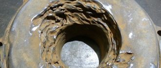
In a similar way, scuffs appear on the surfaces of the journals of the crankshaft and camshaft (photo 1). These surfaces have very high hardness, obtained by nitriding or hardening. Therefore, such great attention is paid to the cleanliness of the internal combustion engine lubrication system and engine oil in terms of the content of solid abrasive particles.
Photo 1. Scoring on the surface of the camshaft journal during examination
Abrasive wear occurs during the operation of all friction pairs where direct interaction of surfaces is observed. Abrasive wear will occur not only due to solid particles entering the interaction zone from the external environment, but also due to particles that are wear products. It would seem that if there are no solid abrasive particles in the friction pair, then there are no initial conditions for abrasive wear. However, in reality the situation is somewhat different. Let's consider the interaction of surfaces at the micro level. In Fig. Figure 2 schematically shows the contact of real bodies under significant magnification (at the micro level).
Figure 2. Frictional interaction of bodies at the micro level in examination
The surfaces of real parts are not absolutely even and smooth - in any case, there will be deviations in shape, and there will also be roughness. And the greater the magnification under which the surface is viewed, the more noticeable the deviation will be. As can be seen from Fig. 2, when parts come into contact due to the waviness of their surfaces, the contact contour will appear predominantly at the tops of irregularities (waves). Each such area will be limited by a contour ΔAc, which is called the contour contact area. These contours are separated from each other by a wave step distance L. The total contour area will be Аc=ΣΔАc. Inside the contour area are the actual contact spots ΔAr. The area determined based on the dimensions of the macrogeometry of the friction surfaces (for Fig. 2a - linear dimensions a and b) is called the nominal contact area ΔAa; this area appears as the main geometric parameter of the friction pair in engineering calculations.
From the point of view of the operation of a friction pair, the actual contact area Ar = ΣΔAr is of greatest interest - this is the area on which the contact of microroughnesses that form the surface roughness occurs. It is within this area that the actual interaction of the surfaces of the parts takes place. The FPC is usually small and occupies no more than 1...10% of the nominal area Aa.
The actual contact area Ar is very important in all physical and chemical processes that can occur at the interface of machine parts. Friction and wear, electrical and thermal conductivity of contacts, rigidity of joints, contact chemical corrosion and strength of press joints - all these phenomena critically depend on the area of actual contact of solids.
In addition to the geometric parameters of the interaction zone of rubbing surfaces, it is also necessary to consider the structure of the friction surfaces, which is shown in Fig. 2b. The external environment for most parts operating in the Earth's atmosphere is air. The air contains free oxygen, which we breathe and which is necessary for the operation of the internal combustion engine. Oxygen interacts with the surfaces of parts, as a result of which oxide layers are formed on them, conventionally shown in Fig. 2b. It is through oxide films that direct contact of surfaces in the actual contact zones occurs. Oxides are mostly hard and brittle. When rubbing surfaces interact, oxides chip off from the surface. And these broken fragments are already solid abrasive particles. Why do aluminum alloys have very low wear resistance? Because despite the low hardness of the aluminum alloys themselves, aluminum oxide has a very high hardness and perfectly “gnaws” the base metal.
One of the main ways to reduce the intensity of abrasive wear is the use of lubricants. The lubricant contains surfactants that are deposited on the surfaces of parts (on top of the oxide film). Due to this, the contact pressures in the actual contact zones are significantly reduced (Fig. 2), and the free surface energy is reduced. As a result, the friction coefficient and wear rate are reduced.
Hydro- and gas-abrasive wear is formed as a result of mechanical action on the surface of solid particles moved by a flow of liquid or gas. The scheme of water-abrasive (and gas-abrasive) effects is shown in Fig. 3.
Figure 3. Scheme of waterjet impact in the examination
A solid abrasive particle 1, which moves together with a flow of liquid or gas (not shown in Fig. 3), hits the surface of body 2. At the moment of interaction of the particle with the surface, wear will be observed. In this case, the material will be torn out by the particle from the surface during its penetration and subsequent movement (only in contrast to abrasive wear, the introduction and movement of the particle will occur due to the kinetic energy of the initial movement of the particle). Also, during water jet wear, fatigue chipping of the surface will be observed.
Fatigue spalling occurs as a result of the accumulation of damage in the surface layer of a part, leading to the destruction of the surface layer. To understand the mechanism of fatigue wear, it is necessary to understand the nature of fatigue failure. Fatigue failure is typical for surfaces that are loaded repeatedly (for example, cyclically). In Fig. Figure 4 shows a Weller diagram that shows the dependence of the maximum stress per cycle on the number of cycles that the material can withstand without destruction. For steel, there is a stress value that it can withstand indefinitely without collapsing - the red curve after 107 loading cycles goes almost horizontally.
Figure 4. Weller diagram in examination
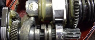
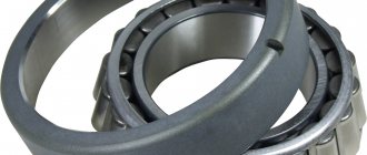
Rubbing surfaces, when exposed to each other, or solid abrasive particles (Fig. 1) cause compressive stresses in the material of the surface layer. If the magnitude of the effective stresses and the number of loading cycles are higher than the Weller curve for the corresponding material, then failure will occur. The greatest stresses during friction or water-abrasive (gas-abrasive) effects will be observed at a certain depth below the surface of the part. Accordingly, the destruction will be the spalling of the surface area under which the fatigue failure of the material occurred. Photo 2 shows a surface damaged by fatigue spalling.
Photo 2. Metal spalling on the rolling surface of the bearing ring during examination
Cavitation destruction is observed in a number of cases on the surfaces of parts in contact with a moving liquid medium. For a moving fluid flow, the law of conservation of energy can be written as the Bernoulli equation:
The essence of this equation is as follows: the sum of the kinetic (depending on the speed of movement) energy of fluid movement () and potential (depending on pressure) energy () is always constant. The flow of liquid is not always uniform. In Fig. Figure 5 conventionally shows laminar (a) and turbulent flow of liquid in a pipe. In laminar flow, fluid flows move rectilinearly (for a straight section of pipe) at a constant speed and do not mix. The speed of the flows in the center is slightly lower than that of the flows at the edges due to internal friction of the fluid. In turbulent flow, the direction and speed of the flows are quite chaotic, and active mixing of the liquid occurs. Various types of local resistances act as turbulators, for example, those indicated at the pipe wall in Fig. 5 roughness.
Figure 5. Laminar (a) and turbulent (b) fluid flow during expert analysis
In turbulent flow, fluid flow velocities in individual zones can be quite high. And, in accordance with the Berrnulli equation discussed earlier, a decrease in the total fluid pressure will be observed in these zones. Liquids boil under certain conditions. This condition is as follows: the liquid pressure must be lower than the saturated vapor pressure for a given temperature. If, during a turbulent flow of liquid, the pressure in individual zones decreases so much that the liquid begins to “boil,” then the conditions necessary for cavitation wear of the adjacent surface are formed.
To explain the process of cavitation wear in Fig. 6. shows a diagram of the behavior of a vapor bubble. During turbulent fluid flow, a vapor bubble formed due to a local decrease in pressure. With further movement of this zone (with a bubble), the speed of this zone decreases and the pressure in it increases. The conditions for the existence of a substance in a gaseous state are no longer met. The bubble collapses. Collapse occurs as follows - liquid flows from all sides fill the vapor cavity. And at a certain moment, fluid flows directed from different directions collide. As a result, a shock occurs - a local, but very noticeable increase in fluid pressure. Through the liquid, this impact is transmitted to the adjacent surface of the part and loads it. Repeated exposure causes fatigue chipping of the surface.
Figure 6. Scheme of formation and collapse of a vapor bubble in the examination
Note that cavitation destruction of car parts occurs extremely rarely. There were destructions of parts of the cooling system due to errors made in the design of individual internal combustion engines. Note that the principle of cavitation destruction described above forms the basis for the operation of various ultrasonic devices designed to clean internal combustion engine parts during maintenance and repair. The only difference from what was described above is that the local decrease in pressure occurs not due to a local increase in speed, but due to the fact that the emitter vibrates in the liquid at an ultrasonic frequency - when oscillating, the emitter carries the liquid with it, which creates a decrease in pressure in it.
Corrosive destruction is caused by chemical and physico-chemical interaction of the surface of the part with the environment. This kind of interaction, as a rule, leads to a decrease in the basic performance characteristics of the material. A striking example is the “transformation” of steel into rust under the influence of water and oxygen. From the point of view of the operation of friction pairs, of particular interest is corrosion-mechanical destruction, the essence of which is to increase the intensity of wear of various types (abrasive, hydroabrasive, cavitation, etc.) of material weakened as a result of corrosion. This can be illustrated as follows: steel can only be processed with a sufficiently strong and hard tool, and rust (a product of the corrosive destruction of steel) can be destroyed even with a fingernail.
Hydrogen wear. The essence of hydrogen wear is as follows: if a hydrogen ion is present at the surface of a part, then due to its small size this ion penetrates deep into the material. As you know, steel is an alloy of iron and carbon. Hydrogen has a greater affinity for carbon than steel. Accordingly, hydrogen “takes away” a carbon atom from iron and forms a methane molecule (CH4) with it. This molecule has a relatively large size and, after its formation, begins to locally stretch the material - that is, it creates stress in it. The destruction is also facilitated by the fact that the metal begins to stretch in the decarbonized zone (due to which the strength of the material is reduced). That is, hydrogen wear cannot be called wear in full - this phenomenon only leads to the intensity of wear of other types after the material has been softened due to exposure to hydrogen.
In the scope of this article, we hope you will be able to objectively understand the judgments based on expert opinions. Perhaps this information will be of interest to any specialist in the field of automotive diagnostics. The expert, undoubtedly, must have this knowledge and use it during the research.
Specialist Alexander
Gas abrasive
This subtype of abrasive wear differs from it in that solid abrasive particles move in the gas flow. The surface material crumbles, is cut off, and is deformed. Found in equipment such as:
- pneumatic lines;
- fan and pump blades for pumping contaminated gases;
- domain installation nodes;
- components of solid fuel turbojet engines.
Often, gas abrasive effects are combined with the presence of high temperatures and plasma flows.
Beginning of the form
End of form
Some features of erosive wear
When considering the types of friction and wear, one should not lose sight of the so-called erosive wear. In simple terms, this is the destruction of surfaces under the influence of the environment.
In engineering, this concept refers to the destruction of the surfaces of machine parts and mechanism components under the influence of environmental factors. Such influencing factors include air and liquid flows, steam or various gases. The cause of wear is, as before, friction. Only in this case, the surface is affected not by abrasive particles, but by gas or liquid molecules.
During this process, microcracks appear. Molecules of liquid and steam under high pressure penetrate into them and contribute to the destruction of all surface layers of products.
The liquid or steam may also contain abrasive particles in suspension. In this case, such a mixture will cause abrasive-erosive destruction and wear.
Waterjet
The effect is similar to the previous one, but the role of the abrasive carrier is performed not by a gaseous medium, but by a liquid flow.
The following are susceptible to this effect:
- hydrotransport systems;
- hydroelectric power station turbine units;
- components of washing equipment;
- mining equipment used for washing ore.
Sometimes waterjet processes are aggravated by exposure to an aggressive liquid environment.
Cavitation
Pressure drops in the liquid flow flowing around the structure lead to the appearance of gas bubbles in the zone of relative rarefaction and their subsequent explosive collapse with the formation of a shock wave. This shock wave is the main active factor in the cavitation destruction of surfaces. Such destruction occurs on the propellers of large and small ships, in hydraulic turbines and technological equipment. The situation can be complicated by exposure to an aggressive liquid medium and the presence of an abrasive suspension in it.
7.3. Damage to rolling bearings
Traces of a radial force applied at one point, constant in direction
, with a rotating inner and stationary outer ring, appear as a continuous mark on the inner ring and local wear of the outer ring (Figure 7.1). []
Figure 7.1 – Traces of radial force, constant in direction: | |
a) a continuous wear pattern on the inner ring; | b) local wear of the outer ring |
If the inner ring is stationary and the outer ring is movable, then the effect of a constant radial force will manifest itself in the form of a continuous wear pattern on the outer ring and local wear on the inner ring.
When the outer ring of the bearing is deformed
As a result of deviations in the shape of the seat, small-scale chipping will appear on the outer fixed ring at two points (Figure 7.2).
Figure 7.2 – Spot-like spalling in two places on the raceway of the outer ring of a double-row spherical radial roller bearing when the shape of the bearing cover seat deviates
Radial force applied at one point, performing periodic oscillatory motion in a limited sector
leads to local wear of the outer and inner rings of the bearing (Figure 7.3). This type of wear is typical for hinged mechanisms in which the shaft performs oscillatory movements.
Figure 7.3 – Local wear of the treadmill of the outer ring of a double-row radial roller bearing during oscillatory motion
Radial force rotating with the shaft
, will lead to the appearance of a permanent wear mark on the stationary outer ring and local chipping on the inner ring (Figure 7.4).
Figure 7.4 – Local spalling of the inner ring of a ball bearing under rotating radial force, a stationary outer ring and simultaneous exposure to axial force
Axial force acting in the longitudinal direction
, causes displacement of wear marks on the bearing rings (Figure 7.4). Additionally, the impact of axial force can be judged by the presence of light spots at the ends of the rollers (Figure 7.5).
Figure 7.5 – Highlighting on the ends of the rollers of one of the running tracks of a double-row radial roller bearing under the influence of an axial force
A bearing assembly has both fixed and moving contacting surfaces of parts. Inspection of a rolling bearing is carried out sequentially from the bearing seating surface in the mechanism housing to the seating surface of the inner ring on the shaft.
If the surfaces of the inner ring and shaft are stationary, then the inner ring of the bearing has a matte surface (Figure 7.6).
Figure 7.6 – Matte surface of the inner ring of the bearing with a fixed fit on the shaft
Loose bearing seat
as a result of installation and operation errors, it often leads to rotation of the bearing on the shaft and in the housing (Figure 7.7). Rotation of the bearing is accompanied by an increase in the temperature of the unit, a change in the nature of noise and vibration and leads to unacceptable wear of housing parts.
Figure 7.7 – Traces of turning the bearing rings
Fretting corrosion
occurs when contacting surfaces move under the influence of variable forces or vibrations. Manifests itself in the form of intense oxidation of surfaces, dark spots on the seating surfaces of bearing rings (Figure 7.8). Leads to knocking and shock when the bearing operates. With further development, it can cause the initiation of fatigue cracks.
Figure 7.8 – Traces of fretting corrosion on the seating surface of the ball bearing rings: | |
a) internal; | b) external |
If the load is unevenly distributed along the length of the roller or between the rows of rolling elements of a double-row bearing (Figure 7.9), then the life of the bearing is significantly reduced. Reason: misalignment of the bearing housing
.
Figure 7.9 – Uneven chipping when bending the shaft: | |
a) along the length of the rollers of the radial roller bearing; | b) on the running tracks of a double-row radial spherical ball bearing |
Inspection of the outer end surfaces of the bearing rings allows you to confirm the rotation of the rings
or determine
the presence of contact between the bearing and a nearby part
(Figure 7.10).
Figure 7.10 – Ring marks on the end surface of the inner ring – the result of contact of the bearing ring with a stationary part
Inspection of the running tracks of the outer and inner rings allows us to establish the nature of the contact between the rolling elements and the running track. Shaft misalignment
relative to the bearing housing can be fixed along a triangular trace with the oscillatory nature of the bearing loading (Figure 7.11).
Figure 7.11 – Triangular shape of contact between the ring and the roller when the shaft is misaligned relative to the housing of a double-row roller radial bearing
Cracks across treadmills are the result of dynamic loads, impacts or installation errors
(Figure 7.12a). Chips of the sides of the rings are the result of the dynamic effects of axial force (Figure 7.12b).
Figure 7.12 – Impact load results: | |
a) transverse crack on the bearing ring; | b) chips of the sides of the ring |
Cracks located along the bearing ring are the result of the lack of thermal clearances
when the mechanism heats up. The axial force arising during thermal expansion leads to the disappearance of the radial clearance and the emergence of significant radial forces that can lead to destruction of the outer ring (Figure 7.13).
Figure 7.13 – Destruction of the outer ring of a ball bearing in the absence of a thermal gap
Increased axial play
pairs of angular contact ball bearings, when a longitudinal force occurs, leads to the appearance of edges or small-scale chipping on the non-working part of the treadmill (Figure 7.14).
Figure 7.14 – Non-working part of the treadmill of an angular contact ball bearing with increased axial play and longitudinal load: | |
a) facet; | b) smallpox-like spalling |
Brinelling manifests itself in the appearance of dents on the treadmills with a pitch equal to the pitch of the rolling elements. It is a consequence of impact forces during installation
(Figure 7.15).
Figure 7.15 – Brinelling of a thrust ball bearing on treadmills – dents with a pitch equal to the pitch of the rolling elements
False brinelling occurs when lubricant drains
from the rolling surfaces of bearings
of an idle machine
as a result of mechanical vibrations transmitted from operating mechanisms. It manifests itself in the form of damage to the working surface of the bearing, located with a pitch equal to the pitch of the rolling elements (Figure 7.16).
Figure 7.16 – Traces of false brinelling on the working surface of the outer ring of a roller angular contact tapered single row bearing
Separator damage is the most serious type of damage. If the separator is damaged, other parts may be damaged due to vibration, wear, jamming and distortions (Figure 7.17). The most common cause of cage failure is problems with lubrication and deformation of the outer rings.
. This leads to the emergence of uneven forces on the rolling elements and the impact of destructive forces on the cage.
Figure 7.17 – Destruction of the separator | |
Rolling bearings must be replaced if one of the following damages is present [4]:
- fatigue or corrosion pits on raceways and rolling elements;
- cracks, chips of sides, rings, rolling elements;
- cracks, fracture of the separator;
- wear, breakage of separator rivets;
- nicks on the separator;
- scoring, corrugation, wear or dents on the working surfaces of rings and rolling elements;
- surface corrosion or tarnish on work surfaces;
- increase in radial clearance.
Adhesive
With prolonged friction, accompanied by plastic deformations of the participants in the rubbing pair, periodic convergence of surface areas occurs at a distance that allows the forces of interatomic interaction to manifest themselves. The interpenetration of atoms of substance of one part into the crystalline structures of another begins. Repeated occurrence of adhesive bonds and their interruption lead to the separation of surface zones from the part. Loaded rubbing pairs are subject to adhesive aging: bearings, shafts, axles, sliding bearings.
Features of oxidative wear
This type of wear occurs when a loose film of oxides appears on the surface of rubbing parts, which is quickly removed from the surface as a result of friction. Most engineering materials are prone to oxidation in air at elevated temperatures. Therefore, mechanisms that operate without lubrication and without a cooling system are susceptible to this type of wear of parts.
The greater the rate of destruction of the oxide film and the greater the rate of its formation, the more intense the wear of surfaces.
This type of wear is typical for hinged and bolted joints, various suspension mechanisms, and indeed for all components operating without lubrication.
With increasing friction speed, the temperature of the rubbing surfaces increases. This leads to intensification of destructive processes. An increase in shock loads has a similar effect.
Thermal
The thermal type of aging consists of the destruction of the surface layer of a material or a change in the properties of its deep layers under the influence of constant or periodic heating of structural elements to the plasticity temperature. Damage is expressed in crushing, melting and changing the shape of the part. Characteristic for highly loaded components of heavy equipment, rolls of rolling mills, hot stamping machines. It can also occur in other mechanisms when the design conditions for lubrication or cooling are violated.
Wear due to chipping
The presented classification of types of wear will not be complete if we lose sight of the so-called wear due to chipping. Its essence is as follows. Under severe (possibly even extreme) operating conditions, the surface layers of rubbing parts undergo structural and phase transformations. The reasons in different cases are elevated temperatures, heating and cooling conditions, high pressure and others. The properties of the resulting layers differ significantly from the properties of the original material. As a rule, these phases are brittle and break under load.
Thus, on steel and cast iron, during friction without lubrication, characteristic white stripes are formed. These areas cannot be etched even with a solution of nitric or hydrofluoric acids in alcohol. Metallurgists call this formation the white layer. It has a fairly high Rockwell hardness and is very brittle. One laboratory performed phase and structural analysis of the white layer. It turned out that it is a mechanical mixture of martensite and cementite. It also contains a trace amount of ferrite. There is very little of the latter in it and it cannot reduce hardness.
The formation (synthesis) of this substance is accompanied by the occurrence of harmful internal tensile and compressive forces. When the vectors of internal stresses coincide with external loads on the part, minor cracks form on its surface in the area of the white layer. These microcracks are stress concentrators and accumulators, which leads to brittle fracture of the product as a whole.
Types of wear
The classification of types of wear and tear from the point of view of the physical phenomena that cause it in the microcosm is complemented by systematization according to the macroscopic consequences for the economy and its subjects.
In accounting and financial analytics, the concept of wear and tear, which reflects the physical side of phenomena, is closely related to the economic concept of depreciation of equipment. Depreciation refers to both the decline in value of equipment as it ages and the attribution of a portion of that decline to the cost of the products produced. This is done with the aim of accumulating funds in special depreciation accounts for the purchase of new equipment or partial improvement of it.
Depending on the causes and consequences, they distinguish between physical, functional and economic.
Ways to combat thermal cracks
The most effective measure to combat thermal cracks is to provide intensive cooling. Special oils and lubricants can be used for this. In the case of train wheels, this measure, for obvious reasons, is not suitable. In this case, you can play with the chemical composition of the material and select a steel grade that is more advantageous from this point of view. Certain grades of alloy steel have a low coefficient of expansion. And this property can be used profitably.
Physical deterioration
This refers to the direct loss of the design properties and characteristics of a piece of equipment during its use. Such loss may be either total or partial. In case of partial wear, the equipment undergoes restoration repairs, returning the properties and characteristics of the unit to the original (or other pre-agreed) level. If the equipment is completely worn out, it must be written off and dismantled.
In addition to degree, physical wear and tear is also divided into types:
- First. Equipment wears out during planned use in compliance with all standards and regulations established by the manufacturer.
- Second. Changes in properties are due to improper operation or force majeure factors.
- Emergency. Hidden changes in properties lead to sudden emergency failure.
The listed varieties apply not only to the equipment as a whole, but also to its individual parts and assemblies
Abrasive wear due to solid particles (grains)
This type of mechanical wear occurs when abrasive grains come into contact with metal or other material. The hardness of such particles significantly exceeds the hardness of the metal itself. This leads to deformation of the materials of friction pairs, the occurrence of fatigue stresses, and surface abrasion.
If the mechanism operates under conditions of frequent alternating loads, then the effect of the harmful effects of abrasive is enhanced. In this case, the abrasive particle leaves not only marks on the metal surface, but also dents.
As the fraction of the abrasive substance increases, abrasive wear also increases. Abrasive particles are very hard, but at the same time fragile. Therefore, large bodies can be ground into smaller ones.
Functional wear
This type is a reflection of the process of obsolescence of fixed assets. This process consists of the appearance on the market of the same type, but more productive, economical and safe equipment. The machine or installation is still physically in good working order and can produce products, but the use of new technologies or more advanced models appearing on the market makes the use of outdated ones economically unprofitable. Functional wear can be:
- Partial. The machine is unprofitable for a complete production cycle, but is quite suitable for performing a certain limited set of operations.
- Full. Any use results in damages. The unit is subject to write-off and dismantling
Functional wear is also divided according to the factors that caused it:
- Moral. Availability of technologically identical, but more advanced models.
- Technological. Development of fundamentally new technologies for the production of the same type of product. Leads to the need to rebuild the entire technological chain with a complete or partial update of the composition of fixed assets.
If a new technology appears, as a rule, the composition of the equipment is reduced and the labor intensity decreases.
Economic wear and tear
In addition to physical, temporary and natural factors, the safety of equipment characteristics is also indirectly influenced by economic factors:
- Fall in demand for manufactured goods.
- Inflationary processes. Prices for raw materials, components and labor resources are rising, while at the same time there is no proportional increase in prices for the company's products.
- Price pressure from competitors.
- An increase in the cost of credit services used for operating activities or for updating fixed assets.
- Non-inflationary price fluctuations in raw materials markets.
- Legal restrictions on the use of equipment that does not meet safety standards
environment.
Economic wear and tear
Both real estate and production groups of fixed assets are susceptible to economic aging and loss of consumer qualities. Each enterprise maintains registers of fixed assets, which take into account their depreciation and the progress of depreciation accumulations.
The main reasons and ways to determine wear
To determine the degree and causes of wear and tear, a commission on fixed assets is created and operates at each enterprise. Equipment wear is determined in one of the following ways:
- Observation. Includes visual inspection and complex measurements and tests.
- According to service life. It is defined as the ratio of the actual period of use to the standard one. The value of this ratio is taken as the amount of wear in percentage terms.
- a comprehensive assessment of the condition of an object is made using special metrics and scales.
- Direct measurement in money. The cost of acquiring a new similar unit of fixed assets and the cost of restoration repairs are compared.
- profitability of further use. The reduction in income is estimated taking into account all the costs of restoring properties in comparison with the theoretical income.
Which method to use in each specific case is decided by the fixed assets commission, guided by regulatory documents and the availability of source information.