Main parameters and areas of application
The parameters that determine the characteristics of the pitch thread include:
- coil profile (its geometric shape and angle of inclination);
- thread pitch (distance between points of the same name);
- dimensions of the three main circles (middle, inner and outer);
- thread progress and cutting.
Each of the parameters has its own notation system. A distinctive feature is the step unit. For example, a modular thread has a designation called module. In a pitch system, it is measured in pitches. For example, a step equal to two pitches corresponds to 6.28 decimeters. Pitch is equal to the ratio of the number of teeth of the wheel being cut to its diameter. To systematize existing sizes and convert them into the most understandable systems, a special table is used.
Both types of thread (modular and pitch) have several types of thread profiles:
- in the shape of an Archimedean spiral;
- involute (a second-order curve, each point of which is tangent to a given circle);
- trapezoidal shape.
The size of the threads depends on the application of the thread.
Each of the diameters is defined as the diameter of an imaginary cylinder. For example, the average diameter is determined for a cylinder whose radius is half the distance from the top point of the thread to its bottom point (groove). The basic designation unit for these types of connections is the inch. You can measure the main parameters with a standard measuring instrument.
Modular and pitch threads are used in various units where it is necessary to ensure motion transmission. These include worm and worm-tooth gears. They apply:
- in mechanical jacks;
- press;
- lifts;
- extruders.
This type ensures reliable engagement of the gear teeth on the worm. This is achieved by setting the pitch profile to 40 degrees for pitch connections. In metric threads it is 60 degrees. Some machines, such as extruders, use pitch threads. Its peculiarity is the use of a variable step.
Slicing technology
Cutting modular and pitch shapes is carried out on metal-cutting machines in the following ways:
- cutter on screw-cutting lathes;
- modular cutter on milling machines;
- special finger cutters.
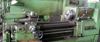
The first method of pitch cutting provides high accuracy, but has low productivity. With its help, pitch threads are cut on worm shafts that require high precision motion transmission. This method is used in enterprises with individual or small-scale production.
The second and third methods are considered more productive. The cutter is installed so that its axis of rotation intersects the longitudinal axis of the workpiece shaft strictly at an angle of 90 degrees. To ensure high quality threads (modular or pitch), several passes are made. The most convenient for cutting pitch joints are machines equipped with twin-shaft feed mechanisms or so-called Norton gearboxes.
Before cutting, the machine is set up based on data from special tables that indicate the pitch values. With their help, the required set of gears is installed on a screw-cut guitar with specified gear ratios.
Finger cutters are used for cutting pitch joints on products with large dimensions. To implement pitch cutting, special milling heads are installed that have an individual cutter drive. The first pass is carried out with a slotted finger cutter of a straight-through profile, with a profile angle of 35 degrees.
Classification and main features of threads[edit | edit code]
- Diameter unit (metric, inch, modular, pitch thread)
- Surface location (external and internal threads)
- Direction of movement of the screw surface (right, left)
- Number of passes (single and multi-pass), for example, two-pass, three-pass, etc.
- Profile (triangular, trapezoidal, rectangular, round, etc.)
- The forming surface on which the thread is located (cylindrical thread and tapered thread)
- Purpose (fastening, fastening and sealing, chassis, etc.)
Pipe cylindrical, pipe conical and conical inch
Pipe cylindrical threads have found their application in the construction of pipelines. Manufacturers produce products with threads ranging from 1/16 to 6 inches. At the same time, up to 28 to 11 threads of thread can be applied per inch.
Pipe tapered thread
This type of material is used as a fastening and sealing material. The requirements for it are defined in GOST 6211-81. This document states that the profile must correspond to the inch profile. It is made on a cone with an angle of 1:16.
The base has an angle of 55⁰.
It ensures the tightness of the connection without the use of any additional devices (washers, sealants, etc.). Using this type of connection dramatically reduces the time required to assemble/disassemble the connection. It can be found in supply systems for oil, fuel, steam, etc.
Inch tapered thread
It is most often used to connect elements included in fuel, oil and other pipelines. Not so long ago, it was standardized based on the inch system of measures.
Inch conical die
The base is a triangle with an angle of 60⁰. But, in recent years, in practice they have begun to more often use a conical profile made on the basis of the metric system of measures.
Functional purpose of thread
Screw threading, made on the rod or inside the nut, allows you to:
- hold the parts at the distance specified in the drawing documentation;
- fix structural elements from displacement relative to each other;
- ensure tight fit of parts;
- protect the assembly from destruction (if excessive load occurs, the screw or pin breaks);
- convert rotational motion into translational motion (for example, the lead screw of a lathe ensures the movement of the support).
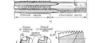
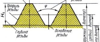
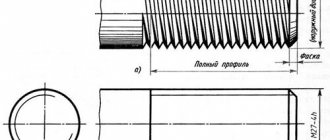
Thread profile elements
The elements of a thread profile are its sides, angle, crest and valley. The profile angle is the angle between the sides of the coil, measured in the center plane. This angle (Fig. 1, a) is designated by the letter α. The top of the profile is the line connecting its sides along the top of the turn (P, Fig. 1, a, b).
The depression of the profile is the line forming the bottom of the helical groove (R, Fig. 1, a, b). The outlines of the top and valley can be flat-cut (Fig. 1, a) or rounded (Fig. 1, b).
Classification and main features
Threads are divided into categories according to the following characteristics:
- diameter measurement scale (metric, pitch, inch or modular);
- position on the surface (outside the rod or inside the channel drilled into the part);
- direction of turns (there are cuts with left or right turns);
- number of cutting passes (standard single-pass or special multi-pass);
- profile (triangular, trapezoidal, rectangular, spherical);
- relative position of the edges of the threaded part (cylindrical or conical);
- purpose (fastening, chassis and a number of others).
Connection parameters
The minimum pipe thread diameter is 1/16″, which corresponds to 7.72 mm, the maximum is 6″ or 163.8 mm. There are 16 standard sizes in total, depending on the outer diameter of the connection, which is measured along the upper ridges. The internal diameter is determined by the lowest points at the opposite ends of the ridge.
Another leading characteristic is the cutting pitch, which is determined by the distance between adjacent thread crests or valleys. The pitch is the same on any section of the connection and is measured by the number of turns per technical inch equal to 25.4 mm. This characteristic also depends on the profile height and is equal to half the difference between the internal and external diameters.
Properties of common types of threads
Today there are many standards by which threaded products are produced. Each of them implies a single set of technical characteristics, formed based on the purpose of the product. To function effectively in different areas, certain combinations of size, shape, number of passes, direction of rotation and additional parameters are required. Among the modern types, we can distinguish several categories that are common in specific industries and meet the standards of international thread marking:
- Metric M, MK, MJ, EG-M;
- Inch UNC, UNF, UTS, BSW, BSF, NPT;
- Pipe G, R;
- Round Kr;
- Edison E;
- Trapezoidal Tr;
- Thrust S, S45o;
- Oil range.
Most of the threaded parts are produced for fastening connections, which are intensively used in mechanical engineering. Russian enterprises more often use metric single-start right-hand threads with a triangular profile for the manufacture of fasteners. To ensure tightness, fastening and sealing connections are used, produced for the pipe industry according to the inch standard system. It is advisable to use fasteners with multi-start threads under increased loads to enhance strength.
Round threads are used to connect water supply fittings when installing utilities. It is designed for operation of mechanisms in aggressive environments. Edison round thread is designed specifically for use in electrical engineering. The standard incandescent lamp base is made using this variety. Trapezoidal and thrust threads are designed to transmit movement. They are characterized by certain angles of inclination. Running threads of both types are used in special equipment.
Important point. In addition to the listed types, rectangular running threads are also used in domestic mechanical engineering. This type is not standardized because it is difficult to manufacture, although it is widely used for the manufacture of screw mechanisms and jacks. The efficiency of rectangular threads is higher than that of trapezoidal threads, to which it, in turn, is inferior in strength.
General technical parameters of thread
When manufactured according to standards, international marking of threads is carried out taking into account a single set of technical parameters. The nominal diameter (D) of the external thread is measured at the tops of the profile, the internal (D1) - at the recesses, and the average (D2) is calculated on their basis. When it comes to similar characteristics of the inner surface, parameters D and D1 are determined according to the opposite principle. To measure the distance between turns, the thread pitch (P) is used, which is calculated in fractions of a meter or an inch.
Another main indicator is stroke (Ph), which is equal to one revolution of the element along the axis of rotation. In a single-start thread, the value corresponds to the parameter P, while a multi-start thread requires its multiplication by the number of starts (n). Important technical characteristics are the helix angle, the height of the original triangle and the thread cut. There are other significant indicators. Among them are pitch deviation, lead-in, and thread make-up length. When processing conical surfaces, the cone angle, connection and contact length are additionally taken into account.
Metric threads M, MK, MJ, EG-M
The international marking M is assigned to general purpose threads with a diameter of 1-600 mm. The designation MK is intended for leak-tight connections provided by the conical shape. MJ - cylindrical threads used in areas that involve operation at high temperatures and require increased fatigue strength. Dimensions range from 1.6-200 mm. Metric thread EG-M is used in the manufacture and repair of bushings and wire inserts as an amplifier of load-bearing capacity.
Geometric parameters
The parameters determine the purpose of geometric metric cutting for joining materials. Basic designations:
- The nominal diameter of the thread is designated by the letter D. The internal type of fastener is defined as d, external with a capital letter.
- Depending on the location, there is a definition of the average thread diameter. Identified by letters and numbers, for example D2.
- In the drawings there is a thread parameter, such as the internal diameter, the designation is made by the number 1, for example d
- To calculate the mates in the connection structure, the inner circumference of the product is used.
- Determining the distance between the top points of closely spaced threads is called the thread pitch. To distinguish parts with a repeating diameter in the presented drawing, a division into a main step and a step with smaller geometric parameters is used, the designation is set to the letter P.
- The thread stroke and its parameters correspond to the movement of the linear value of the screw fastening connection per full revolution, as well as the distance between the peaks and valleys formed on the surface.
- The height of the triangle forms the dimensions, connection parameters, profile, and the letter H is used for the designation.
Table of metric thread sizes
Parameters such as the average thread diameter must be presented using the accompanying documentation. For standardized display, GOST standards are used. The standards stipulate the display of the main dimensions of connecting products and parameters; GOST 24705-2004 applies to all types of threaded connections.
Metric cuttings of connections are used in the manufacture of objects by applying parameters to drawings. Thread sizes are described in the table, with nominal diameters ranging from 1 to 600 millimeters. The pitch is determined in the table from 0.25 to 6 mm, symbol when displayed through “x”, for example M8 × 1.5.
To produce internal cutting, tools are used (cutters, taps, sliding taps, group cutters, knurling rollers) produced at serial tool factories. The production of special cutting tools is carried out in the tool shops of large production associations.
The most common method is cutting using taps. Threads can be cut manually and on various types of machines. In mass production, automatic machines are used for cutting nuts; an example of such equipment is the MH 63 machine. It is used for cutting threads from M12 to M20 with different pitches. Taps with a curved shank are used as cutting tools. The power of the installed engine allows processing both non-ferrous metals and high-alloy steels.
In conditions of mass production of nuts, so-called automatic knurling machines are used. They are designed in such a way that they allow cutting on nuts of different sizes from M5 to M60 with different productivity, from several to tens of pieces per minute, and purposes, for example, intended for fixing anchors.
For cutting in body parts, multi-spindle units are used, which allow processing several holes at once. Such equipment is used in the processing of propulsion systems for automobile and tractor equipment.
Cutting internal threads is a rather difficult process, during which both the tool and the workpiece experience severe stress, leading to an increase in temperature. For this purpose, lubricating and cooling liquids (coolants) are used.
For manual production, castor oil is used, for example.
Manufacturing methods[edit | edit code]
The following methods for obtaining threads are used:
- blade cutting;
- abrasive processing;
- rolling;
- extrusion by pressing;
- casting;
- electrophysical and electrochemical processing.
The most common and universal method of producing threads is blade cutting. These include:
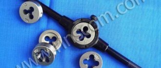
- cutting external threads with dies;
- cutting internal threads with taps;
- turning external and internal threads with thread cutters and combs;
- thread milling of external and internal threads using disk and worm cutters;
- cutting external and internal threads using thread-cutting heads;
- restoration of damaged external and internal threads with a regular or specialized file;
- whirlwind processing of external and internal threads.
Rolling is the most highly productive method of thread processing, ensuring high quality of the resulting thread. Thread rolling includes:
- rolling external threads with two or three rollers with radial, axial or tangential feed;
- rolling external and internal threads using thread rolling heads;
- rolling external threads with flat dies;
- rolling external threads with a roller-segment tool;
- rolling (extruding) internal threads using chipless taps.
Abrasive processing of threads includes grinding with single-thread and multi-thread wheels. It is used to obtain accurate, mainly running threads.
Extrusion by pressing is used to produce threads from plastics and non-ferrous alloys. Not widely used in industry.
Casting (usually under pressure) is used to produce low-precision threads from plastics and non-ferrous alloys.
Electrophysical and electrochemical processing (for example, electrical discharge, electrohydraulic) is used to produce threads on parts made of materials with high hardness and brittle materials, for example, hard alloys, ceramics, etc.
Geometric parameters
The parameters determine the purpose of geometric metric cutting for joining materials. Basic designations:
- The nominal diameter of the thread is designated by the letter D. The internal type of fastener is defined as d, external with a capital letter.
- Depending on the location, there is a definition of the average thread diameter. Identified by letters and numbers, for example D2.
- In the drawings there is a thread parameter, such as the internal diameter, the designation is made by the number 1, for example d
- To calculate the mates in the connection structure, the inner circumference of the product is used.
- Determining the distance between the top points of closely spaced threads is called the thread pitch. To distinguish parts with a repeating diameter in the presented drawing, a division into a main step and a step with smaller geometric parameters is used, the designation is set to the letter P.
- The thread stroke and its parameters correspond to the movement of the linear value of the screw fastening connection per full revolution, as well as the distance between the peaks and valleys formed on the surface.
- The height of the triangle forms the dimensions, connection parameters, profile, and the letter H is used for the designation.
Table of metric thread sizes Parameters such as the average thread diameter must be presented using the accompanying documentation.
GOST standards are used for standardized display. The standards stipulate the display of the main dimensions of connecting products and parameters; GOST 24705-2004 applies to all types of threaded connections. Metric cuttings of connections are used in the manufacture of objects by plotting parameters on drawings. Thread sizes are described in the table, with nominal diameters ranging from 1 to 600 millimeters. The pitch is determined in the table from 0.25 to 6 mm, symbol when displayed through “x”, for example M8 × 1.5.
To produce internal cutting, tools are used (cutters, taps, sliding taps, group cutters, knurling rollers) produced at serial tool factories. The production of special cutting tools is carried out in the tool shops of large production associations.
The most common method is cutting using taps. Threads can be cut manually and on various types of machines. In mass production, automatic machines are used for cutting nuts; an example of such equipment is the MH 63 machine. It is used for cutting threads from M12 to M20 with different pitches. Taps with a curved shank are used as cutting tools. The power of the installed engine allows processing both non-ferrous metals and high-alloy steels.
In conditions of mass production of nuts, so-called automatic knurling machines are used. They are designed in such a way that they allow cutting on nuts of different sizes from M5 to M60 with different productivity, from several to tens of pieces per minute, and purposes, for example, intended for fixing anchors.
For cutting in body parts, multi-spindle units are used, which allow processing several holes at once. Such equipment is used in the processing of propulsion systems for automobile and tractor equipment.
Cutting internal threads is a rather difficult process, during which both the tool and the workpiece experience severe stress, leading to an increase in temperature. For this purpose, lubricating and cooling liquids (coolants) are used.
For manual production, castor oil is used, for example.
History[edit | edit code]
Diagram of a “threaded” joint in a Trigonopterus beetle
For a long time it was believed that the threaded connection, along with the wheel and gear, is a great invention of mankind, which has no analogue in nature. However, in 2011, a group of scientists from the Karlsruhe Institute of Technology published an article in the journal Science about the structure of joints in Trigonopterus oblongus weevils living in New Guinea[6]. It turned out that the legs of these beetles are connected to the body using a trochanter, which is screwed into the coxa (coxa) - an analogue of the hip joint in insects. On the surface of the trochanter there are projections resembling a conical screw. In turn, the surface of the coke is also equipped with a threaded recess. Such a connection provides a more reliable attachment of the limbs than a hinged one, and guarantees greater stability to the insect leading an arboreal lifestyle.
The use of helical surfaces in technology began in ancient times. It is believed that the first screw was invented by Archytas of Tarentum, a philosopher, mathematician and mechanic who lived in the 4th-5th centuries BC. e. The screw invented by Archimedes, which was used to move liquids and bulk solids, is widely known. The first fasteners with threads began to be used in Ancient Rome at the beginning of our era. However, due to their high cost, they were only used in jewelry, medical instruments and other high-value items.
Running and fastening threads were widely used only in the Middle Ages. The production of external threads was carried out as follows: a rope greased with chalk or paint was wound onto a cylindrical blank, then a helical groove was cut along the resulting spiral marking. Instead of internally threaded nuts, bushings with two or three pins were used.
In the XV-XVI centuries, the production of three- and tetrahedral taps for cutting internal threads began. Both mating parts with external and internal threads for screwing were adjusted to each other manually. There was absolutely no interchangeability of parts.
The prerequisites for the interchangeability and standardization of threads were created by Henry Maudslay around 1800, when the screw-cutting lathe he invented made it possible to cut precise threads. He made the lead screw and nut for his first machine by hand. He then machined the screw and nut to a higher precision. Replacing the first screw and nut with new, more precise ones, he turned out even more precise parts. This continued until the accuracy of the carving stopped increasing.
For the next 40 years, interchangeability and standardization of threads occurred only within individual companies. In 1841, Joseph Whitworth developed a system of fastening threads which, due to its adoption by many English railway companies, became a national standard for Great Britain, called the British Standard Whitworth (BSW). The Whitworth standard served as the basis for the creation of various national standards, for example, the Sellers standard in the USA, the Löwenherz thread in Germany, etc. The number of national standards was very large. Thus, in Germany at the end of the 19th century there were 11 carving systems with 274 varieties [ source not specified 1227 days
].
In 1898, the International Congress for the Standardization of Threads in Zurich defined new international standards for metric threads based on Sellers threads, but with metric dimensions.
In the Russian Empire, there was no standardization of threads at the state level. Each enterprise that produced threaded parts used its own standards based on foreign analogues.
The first measures to standardize threads were taken in 1921 by the People's Commissariat of Railways of the RSFSR. Based on German standards for metric threads, he issued tables of norms NKPS-1 for threads used in railway transport. The tables included metric threads with diameters from 6 to 68 mm.
In 1927, based on these tables, the standardization committee under the Labor and Defense Council developed one of the first state standards of the USSR - OST 32. In the same year, OST 33A was developed for threads according to the Whitworth standard. By the beginning of 1932, OSTs for trapezoidal threads were developed based on the modernized American Acme standards.
In 1947, the International Organization for Standardization (ISO) was founded. ISO thread standards are currently generally accepted throughout the world, including in Russia.
Implementation of a system of standards in Russia
The Congress, held in Zurich at the end of the 19th century, became a significant event for the standardization of carvings in Europe. But in Russia, the beginning of the process was delayed until 1921, when, on the initiative of the People's Commissariat of Railways, the first standards were developed specifically for railway transport. The NKPS-1 tabular system, based on German metric thread standards, included sizes 6-68 mm. It turned out to be the basis for the creation of OST 32 in 1927, followed immediately by OST 33A. It is based on the Whitworth system.
The development of USSR state standards did not stop there. Modernization of Acme standards issued in the United States led to the standardization of trapezoidal threads in 1932. The abbreviation GOST for national systems was adopted eight years later. In 1947, ISO thread standards appeared, which are still used today. Since then, Russia has taken into account both state and international standards, according to which domestic products for threaded connections are produced at the world level of quality.
Designation rules
Designations in connections with pitch threads are determined by the requirements of existing standards. Each of them includes the following elements:
- A letter indicating belonging to a certain type of connection.
- Size (indicated in millimeters or inches);
- Step size;
- Direction (left – LH or right – RH).
- For the multi-start thread option, the number of starts is additionally indicated.
- Dimensions of the required tolerance zone (has an alphanumeric designation).
- Make-up length.
The tolerance zone of each diameter is indicated by a set of numbers and letters. The numbers indicate the accuracy class, the letters determine the size of the main deviation. This parameter is indicated by a Latin letter and number. In the first place is a symbol indicating the size of the tolerance field for the average diameter. This is followed by the tolerance size for the outer diameter. If these parameters match, the designation is applied only once.
Existing standards use three length designations, the so-called make-up. They are designated by capital Latin letters. The normal length has the symbol N (usually it is not included and is taken by default). The short one is denoted by a capital S, the long one by a capital L.
These symbols are located after the tolerance zone indication. They are separated by a long horizontal line.
The rules for applying symbols are given in GOST 24705-2004 (ISO 724:1993). GOST 16093 is considered the most modern. In 2005, changes and additions were made to the text. The main provisions of the international standards ISO 965-1 and ISO 965-3 are posted there. The pitch system is used in North America and is specified in the international standard ANSIB1.9. The average diameter size is marked with the symbol “E”.
Decoding the writing of threads
Graphic materials are designed in accordance with the instructions of GOST 2.311-68 “Image of threads”.
A typical designation structure contains:
- the literal part defining the type;
- numbers corresponding to the nominal size in millimeters or inches;
- pitch (mm) is indicated only as fine, after the “×” sign;
- for multi-start ones, instead of the previous paragraph, the stroke (mm) is given, then the step in parentheses;
- direction: right is the default, left is LH;
- tolerance range or accuracy class;
- make-up length other than normal.
Example 1: М16×1.5LH–6H. Explanation:
- M – metric cylindrical;
- 16 – nominal diameter, mm;
- 1.5 – fine pitch, mm;
- LH – left;
- 6Н – tolerance range, where 6 – degree of accuracy; H – main deviation. Capital letters are used for internal (nuts), hence the threads in the hole.
The screw-in length is not indicated, which means it is normal.
- G – cylindrical pipe;
- 1/2 – thread size, inches; corresponds to the internal diameter of the pipe;
- A – accuracy class.
The designation options are illustrated below.
Round threads Kr
According to GOST 13536-68, threads are applied to pipeline fittings of engineering systems for supplying drinking water or technical liquids, including aggressive media. The Kr marking applies to valve and spindle mechanisms, mixers and other sanitary equipment components for water supply systems. This is a round thread with a profile formed by arcs in the valleys and at the tops, which are connected to the corner by straight lines. Despite the limited scope of operation, the standard is in demand due to the prevalence of products.
Connection parameters
The minimum pipe thread diameter is 1/16″, which corresponds to 7.72 mm, the maximum is 6″ or 163.8 mm. There are 16 standard sizes in total, depending on the outer diameter of the connection, which is measured along the upper ridges. The internal diameter is determined by the lowest points at the opposite ends of the ridge.
Another leading characteristic is the cutting pitch, which is determined by the distance between adjacent thread crests or valleys. The pitch is the same on any section of the connection and is measured by the number of turns per technical inch equal to 25.4 mm. This characteristic also depends on the profile height and is equal to half the difference between the internal and external diameters.
Trapezoidal threads Tr
In running gears, a trapezoidal metric thread with the designation Tr is used to convert rotational motion into translational motion. This type is applied to screws that are functional components of machine tools, lifts and other mechanical equipment. The Tr standard includes right-handed and left-handed, single-start and multi-start threads. The diameter is 10-640 mm. Trapezoidal threads, the parameters of which are regulated by GOST 9481–81, are designed for heavy loads.
What is an inch thread?
Threaded connections are characterized by the following factors: by type of fit: sliding, clearance, transitional, interference fit. According to the use of complementary parts: conventional direct connections and in combination with elements: ball, sleeve, spiral. Without or with a stopper.
- cylindrical or conical shape
- cutting method – external and internal cutting,
- type of direction of the screw line - left and right,
- approaches – multi-entry and single-entry,
- profiling parameter: metric, cylindrical, trapezoidal, conical pipe, conical inch, round, rectangular, thrust,
- Dimension – metric thread or inch pipe thread,
- purpose - for fastening, running threads, regulating,
- type of processing: cutting a part with a cutter, die, tap.
- LiveJournal
- Blogger
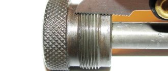
Bushing with inch connection
In modular slicing, the pitch is determined by modules. To convert to mm. "M" is multiplied by the number pi.
Pitch threads are measured in pitches (to determine the number of inches, pi is divided by pitch).
Options
GOST for inch threads 6257 - 81 determines the main precise parameters of the pass pitch and diameter. In this case, the measurement of the outer pipe diameter is equal to the distance between each upper point of the opposing ridges. The diameter of the internal lumen is measured from one point at the bottom of the groove cavity to the opposite point. The thread pitch is a constant value, it is measured by the distances between adjacent ridges or depressions.
Differences between metric and inch threads:
- metric dimensions - in mm, inch dimensions - in inches or their fractions,
- inch threads are characterized by sharper angles of inclination of crests and valleys,
- The threads have a rounded shape.
Upper angle size = 55 degrees, thread pitch is measured by the number of threads.
The following types of products are used in everyday life:
with a parameter of 1 inch - 14 threads, step length 1.814 mm, diameter ¾ or ½,
11 threads in 1 inch - with a pitch size of 2, 309, and a diameter of 1; 1 and ½; 1 and ¼.
Relation between inch and metric threads:
- LiveJournal
- Blogger
Table of ratio between inch and metric threads
Advantages and disadvantages
Advantages of threaded connections:
- high strength and reliability;
- possibility of repeated assembly and disassembly;
- unification of bolts and nuts in accordance with international standards;
- ease of assembly and disassembly of the structure;
- increased force when mating surfaces with a small load applied to the tool.
The most widespread is the bolted connection, in which it is necessary to drill holes of the appropriate size in the mating parts. In case of breakage or damage, simply unscrew the nut and install a new fastener. The body parts remain intact, which reduces the cost of repairs. If it is impossible to make a through hole, then use screws with a screwdriver head or a special bit. Studs are used for components made of light alloys or for units that require periodic disassembly for maintenance or repair.
To install pins or screws, holes are made in the parts, which form zones of increased stress in the metal. If excessive load is applied, partial or complete destruction of the unit or failure of the fastening is possible. To prevent spontaneous loosening, it is necessary to install spring washers or cotter pins or apply sealant to the threads. In a number of components, bolts with a conical edge are used, which prevents spontaneous loosening (for example, fastening car wheel rims to the hub).
A big disadvantage of threaded connections is the presence of stress concentration points along the length of the profile. In addition, the uneven distribution of load across the turns should be taken into account. For example, when using a nut with 10 threads, the first one accounts for 34% of the force, and the last one accounts for less than 1%. For this reason, in standard designs the height of the nut is 0.5-0.8 of the diameter.
When alternating loads are applied, fatigue cracks appear in threaded connections, leading to structural failure. Despite this feature, bolts are widely used in mechanical engineering, in the assembly of bridges and ship hulls, for connecting railway tracks, in aircraft construction or the aerospace industry.
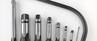
Application of cutters
Thread cutting tools are required to cut threads using a lathe. They are made from high-speed steel, and the requirements for their characteristics are specified by the relevant GOST (18876-73). By design, such cutters are divided into the following types:
- prismatic;
- rod;
- round (disc).
A helical threaded groove on the surface of the workpiece is cut with a bent or straight cutter, and to form internal threads, straight and curved tools are required, which are fixed in a special mandrel. The top of the turning cutter, which is used to cut the turns, must have a configuration that fully corresponds to the profile of the thread being formed.
Cutters for cutting threads: a - rod; b - prismatic multi-profile; c - prismatic single-profile; g - disk multi-profile; d - single-profile disk; e - disk for internal thread; α—rear angle; γ — front angle; φ is the angle of the intake cone; h - installation height of the cutter axis
When forming a thread with a cutter, a number of features of this technology should be taken into account.
- The rake angle of a turning thread cutting tool depends on the characteristics of the material being processed. You can choose this angle within a fairly wide range: 0–250. So, if a thread is cut using a machine on workpieces made of ordinary steels, the rake angle should be 0 degrees; for high-alloy steels that withstand temperature loads well, the rake angle can be 5–100. It can be greater, the higher the viscosity of the material, and the smaller, the higher the hardness and fragility of the metal from which the workpiece processed on the machine is made.
- The tip of the turning tool, which forms a helix on the workpiece, must have a shape identical to the thread profile.
- The rear side corners of the tool are chosen such that the surfaces of the cutter with which they are formed do not rub against the newly formed helical groove. Typically these angles are made equal on both sides of the turning tool. If the helix angle that characterizes the thread is less than 4 degrees, then such angles are chosen in the range of 3–50; if more than 40, then 6–8 degrees.
- Internal threads are cut in already prepared holes, which are obtained by boring or drilling.
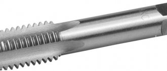
Threading cutters
Natural analogue of thread
Technogenic civilization began to develop thanks to successful solutions copied from the creations of nature. It’s easy to count the exceptions on one hand, and in 2011 there were one fewer exceptions. It was then that the discovery was made about the existence of threaded connections in the structure of living beings. Trigonopterus oblongus is a weevil beetle native to New Guinea. Researchers from Germany's oldest university, Karlsruhe, have discovered that the insect's leg joints are connected by threads rather than hinges like other species.
Important point. In fact, nature has many original ideas, each of which could serve as the first impetus for the invention of carving. Spiral geometry is inherent in the shells of a number of marine inhabitants and epiphytic plants entwining tree trunks, and the method of screwing into the ground is often used by living creatures of various levels to protect themselves from natural enemies or search for food.
An article about the results of the study was published in the most authoritative US periodical, Science. Although it has now been scientifically proven that the primary invention of the threaded connection does not belong to humanity, you should not be disappointed in your own achievements. After all, analogues of wheel and gear mechanisms have not yet been found in nature. Since the introduction of primitive mechanics into mass production, our civilization has stepped far forward, but carving is still relevant, and tools for its application are always in demand.
All about cutting threads on pipes: 4 secrets of a turner
Detachable connections of metal pipelines in a home water supply and sewerage system are made using threads. Inch pipe threads are used on pipe ends and fittings. The diameter of its cutting is determined by the size of inches, or their fractions, where the characterizing value is the number of turns made according to the number of turns on the length of a single inch. The main advantage of a threaded pipe joint is the ability to disconnect and replace one worn part, instead of removing the entire structure and welding installation of another. Cutting inch threads is done using dies, taps, or special cutters.
- What is an inch thread Threads used in everyday life
- Options
- Pipe thread pitch determination
- cylindrical or conical shape
- cutting method – external and internal cutting,
- type of direction of the screw line - left and right,
- approaches – multi-entry and single-entry,
- profiling parameter: metric, cylindrical, trapezoidal, conical pipe, conical inch, round, rectangular, thrust,
- Dimension – metric thread or inch pipe thread,
- purpose - for fastening, running threads, regulating,
- type of processing: cutting a part with a cutter, die, tap.
Bushing with inch connection
In modular slicing, the pitch is determined by modules. To convert to mm. "M" is multiplied by the number pi.
Pitch threads are measured in pitches (to determine the number of inches, pi is divided by pitch).
Supply of thread-cutting equipment
LLC "Russian-Metal" will provide the needs of any enterprise for professional equipment. If you are interested in wholesale supplies of tools for high-quality carving of a certain type, please contact us. A rich assortment, unlimited volumes, prompt shipment, minimum prices and maximum security of transactions are our advantages. Large orders for objects in the capital and the Moscow region are delivered free of charge. Buy thread-cutting equipment wholesale on favorable terms!
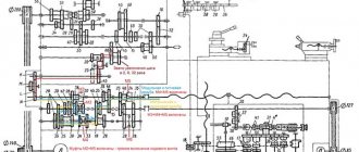
Modular pitch thread
Modular and pitch threads are cut on this machine using a set of interchangeable gears. The pitch increase link allows you to increase the pitch of cut threads by 8 times. [1]
Consequently, when cutting inch, modular and pitch threads, the so-called special multipliers i and 25 4 or their combination appear in the gear ratios. In table 52 shows in which cases special multipliers are used. The presence of l and 25 4 in the gear ratio leads to the need to select gears using the methods outlined above. [2]
Thus, when cutting inch, modular and pitch threads, the so-called special multipliers ie 25 4 or a combination thereof appear in the gear ratios. In table 237 shows in which cases special multipliers are used. [3]
It is used to perform a variety of turning operations, for cutting metric, inch, modular and pitch threads. [4]
Replaceable gears g - j tz zb allow you to adjust for cutting modular and pitch threads. [5]
The presence of movable block gears in the feed box, as well as a set of replacement wheels, ensures the production of inch, metric, modular and pitch threads in a wide range. [6]
The universal screw-cutting lathe 16K25 is designed to perform all kinds of turning operations, including cutting right-hand and left-hand metric, inch, modular and pitch threads; designed on the basis of the 16K20 machine with maximum unification of parts and assemblies for processing product diameters up to 500 mm. Manufactured in two versions: with the longest processed workpiece length up to 2000 mm and with the longest processed workpiece length 710 mm. [7]
The machine type 1M95 is designed to perform turning, milling, drilling, slotting and sharpening work, including cutting metric, inch, modular and pitch threads. [8]
The kinematic chain of the thread cutting mechanism is designed so that all standard metric and inch threads can be cut without changing the guitar gears, and only for cutting normal modular and pitch threads is it necessary to change the guitar gears once. [9]
Using all possible feedbox gears, the machine in question can cut metric threads with pitches from 1 to 12 mm, inch threads with a number of turns from 2 to 24 per 1, as well as many modular and pitch threads. [10]
Spindle speeds and caliper feeds are set using a gearbox and feed box. The feed box provides cutting of metric, inch, modular and pitch threads, which are obtained through a cone set, gear blocks and a guitar of adjustable gears. [eleven]
From shaft VIII, rotation is transmitted through a set of replaceable gears (and a / b - c / d) to shaft IX of the feed box. When and a / b - c / d 40 / 86 - 86 / 64, metric and inch threads are cut, and also obtain table values of the longitudinal and transverse feeds of the caliper, and when and a / b - c / d 60 / 73 - 86 / 36 cut modular and pitch threads. [12]
A guitar with replaceable wheels, which together with the feed box is used for feeding and cutting various threads. The guitar gear, namely gears 32, 35 of shaft VIII, gears 34, 36 of shaft IX and intermediate gear 33, allow for two settings: one setting, along the chain 32 - 33 - 34, is used for feeding and cutting metric and inch threads, the second setting , along the chain 35 - 33 - 36, used for cutting modular and pitch threads. [13]
Making pipe threads
Threading is done on a lathe with a cutter, as well as with the help of dies, combs and taps, manually or mechanically. To clarify the dimensions, you will need a thread gauge tool (comb, gauge) or a caliper.
Pipe thread pitch determination
When cutting metrically, you first need to determine the thread pitch: measure the distance separating the vertices, then divide by the number of threads.
It is important to check first the pitch and profile, then the dimensions of the internal and external diameters.
To find out the step using a ruler, or determine it with a caliper, you need to measure the length of two or three passing steps, then divide by the number of steps. When checking with a thread gauge, the teeth of the nail file should fit tightly and without gaps to the thread being measured.
The accuracy of measurements depends on the following conditions:
- degree of wear and cleanliness of the part;
- convenience of measurement operation,
- cleanliness and appearance of the instrument,
- correct use of the measuring instrument.
Using the inch method, calculate the number of threads per 1 inch of pipe. After processing, verification is required.
To determine the pitch of an inch thread using a fitting (coupling) with an internal thread of the required dimensions, you need to screw a bolt into the part. If it goes in smoothly, tightly, effortlessly, then the pitch and cutting diameter dimensions are selected correctly. To measure the external size of the ridges, screw-on parts of the nozzle are used. If the sizes do not match, use other calibers in turn until they match.
How to use a thread gauge? The plates that are included in the tool are applied to the external, then internal thread of the pipe. If the profile corresponds to the size of the file, it is clarified visually: the free clearance is examined. Exact match means the size parameters indicated on the files (plates) of the thread gauge.
Calipers and micrometers accurately measure only outer diameters, so a more acceptable option is to use a thread gauge.
To avoid mistakes, you need to measure each diameter of the part three times, calculate and select the average value.
To avoid mistakes, you need to measure each diameter of the part three times, calculate and select the average value.
Pipe thread cutting
To accurately cut threads on a lathe (inch), it is important to choose the right tools: an inch thread gauge is used to determine the pitch and design of the cutter.
Cutters for cutting threads are sharpened taking into account the size of the rake angle γ = 0, and are adjusted exactly at the linear height of the center of the machine. Profile angle = 55 degrees.
The thread cutter for external threads is supplemented with durable steel plates (or carbide). The part is processed under the condition that the size of its outer diameter is smaller than the cutting diameter, since during processing the metal is deformed, leading to an increase in the diameter of the workpiece.
To make the internal surface, the workpiece is first bored or drilled, then ridges should be cut to create a ledge of 2 - 2.5 mm. (to accurately determine the last cut of the cutter) then it is removed.
For accuracy, use a template, combine the thread cutting tool with the template, focusing on the clearance in strict accordance with the center line of the machine.
Thread cutting with a cutter on a machine is done in stages.
- After each operation, the cutter is moved to its original position.
- New depth parameters are set and the working passage is repeated, while shifting the cutter to the right or left, and moving the caliper by 0.1 - 0.15 mm.
- Number of passes 3 – 6 roughing, only 3 finishing operations. For them, cutters are used, supplemented with soft-spring holders so that the surface is even and smooth.
- When performing a rough cutting, the turning cutter is mounted on a rigid holder.
- The head of the flat cutter, which performs internal cutting of the part, is adjusted perpendicular to the axis of the part in order to obtain a symmetrical element to avoid distortion.
- To perform finishing operational passes when machine-cutting coils, durable spring holders are used.
- Rough working thread cutting on a machine is done with a cutter mounted inside a rigid structure holder, and the finishing operation is done with a cutter placed inside a springy machine holder.
To simplify the manual cutting operation, use a KLUPP device, consisting of a body with handles, equipped with movable combs, or buy a special die, complete with profile replaceable combs.
A carefully executed inch pipe thread is a guarantee of safe, long-lasting operation of the water supply system at home, so if you do not have specific cutting skills, order the production from a master turner or milling machine.
Classification characteristics of threads
Threads are divided into two main groups. The first includes standardized products, the manufacture of which must comply with international and national standards, determined by multiple criteria. The second category includes non-standard parts with special characteristics, manufactured individually to perform specific tasks. Regardless of compliance with standards, all products have certain parameters on the basis of which classification is carried out. The thread is applied taking into account a number of characteristics:
- The configuration of the contact surface
can be cylindrical or conical; - The profile shape
can be round, triangular, rectangular, trapezoidal; - The location of the thread
is possible on the outer and inner surface of the product; - The operational purpose
can be fastening, running, special; - The direction of the helix
is divided into right and left; - The number of starts
classifies single-start and multi-start threads; - Units of measurement
define metric, inch, modular, pitch sizes.
The metric system is most widespread in Russian industry. When using it, the dimensions of the parts are measured in millimeters. In the production of large-diameter products, inches are used to measure thread parameters. The inch and metric systems are used for the manufacture of elements of threaded connections and screw gears. Modular and pitch threads are more specific. Pi-based calculation methods are used to determine worm parameters for gear-screw mechanisms.
Important point. To convert inches to metric format, you need to multiply the existing indicator by 2.54 to get the result in centimeters. For modular threads, when multiplying the module by pi, the value is converted to millimeters. Calculating pitch pitch is a little more complicated. The size in inches is determined by dividing pi by pitch and then calculated in centimeters if desired.