Electric drill - remember the design of the tool
An electric drill is a type of tool that is designed for drilling different types of materials, including concrete and reinforced concrete. Only for this you will need to use a tool with an impact drilling function or an impact drill. You can find out how the tool works if you take it apart. A brief description of the design of Soviet and foreign-made electric drills is described below.
It should be noted that the design of modern drills of domestic and foreign production differs from the design of Soviet tools. Only these are minor differences, which consist in the absence of reverse on an electric drill, as well as impact drilling. So, structurally, an electric drill consists of two main parts - electrical and mechanical. The mechanical part is based on the following structural elements:
- Gearbox - a set of gears, due to which the speed decreases and the torque from the electric motor shaft increases
- The cartridge is an executive body that is designed to secure working attachments
- Bearings are supporting mechanisms for shafts and axles that ensure their rotation.
- Impact mechanism - in electric impact drills this device is part of the gearbox
The electrical component of any corded electric drill consists of the following elements:
- A commutator type motor consisting of a stator (fixed part), rotor or armature (moving part) and a collector (copper plates or lamellas through which current is supplied to the armature winding)
- Graphite or carbon brushes are a transmission device through which current is transmitted to the rotor winding. Brushes are consumables, and when they spark, this indicates their wear.
- Start button - depending on the model of the electric drill, the switches can be regular or with a built-in speed controller
- Reverse button - Soviet drills do not have such devices. This is a polarity reversal mechanism through which the direction of rotation of the tool chuck changes. Installed separately or integrated into the start button
- A ferrite ring is an element (filter) through which noise in the network is smoothed out
- A capacitor is a filter element that prevents interference from entering the network
- Power cord - the link between the electrical outlet and the tool
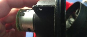
The photo above shows the design of the drill with the main components. Sooner or later, it becomes necessary to repair the drill due to the failure of its individual components and mechanisms. To do this, you first need to inspect the tool, identify the cause of the malfunction, and eliminate it. More details about what types of drill breakdowns there are, how to identify and fix them, are described in the material.
This is interesting!
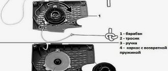
Old Soviet drills do not have a reverse mechanism or an electronic speed controller. Instead of an electronic regulator, a mechanical one is used, consisting of gears of different diameters and numbers of teeth. This method of adjustment is more reliable, since reducing the speed does not affect the power. However, this method of speed control is expensive, as it requires the additional use of a pair of gears. If one pair of gears wears out, you can continue to use the tool. Below are photos showing the design of the mechanical speed controller of an old Soviet drill.
Operating principle and main components
The drill owes its appearance to the demand for underground drilling to replace manual labor with automated labor. In 1870, American inventor Simon Ingersoll introduced the progenitor of the impact drill. In its work, the tool used a steam drive and a drill. The advent of electric motors at the end of the 19th century made it possible to improve the instrument. So, in 1889, engineer Arthur James Arnot proposed using an electric motor in conjunction with a drill, and already in 1895 a tool appeared that could be held freely in the hands when working.
In early 1917, Arthur Arnot, working for the BLACK&DECKER company, connected a button to a drill and added a pistol grip, making the device one of the most popular power tools in the world. Since then, the design of the electric drill has not undergone fundamental changes.
A classic drill only works in drilling mode , but with the development of manufacturing technology, modern devices began to be equipped with an impact mode. When connected to a 220-volt network, a gear drill, converting electrical energy into mechanical energy, forces the chuck attached to the device mechanism to perform a rotational movement. The number of revolutions of the cartridge is controlled using a rheostat built into the power button, and the direction of rotation is set by reverse. The drill, clamped into the chuck, due to its shape and under the influence of high speed of rotation, easily makes a hole in hard or soft material.
To carry out an impact, the device uses reciprocating movements resulting from the operation of the motor. A ratchet representing a toothed ring is installed on the axis of the cartridge, and teeth are made on the body to create a stop. When the impact drill is switched to hammer drill mode, the ratchet engages and then slides off the fence. The shaft strikes in a vertical direction.
Before you start repairing a drill with your own hands, you need to determine which part of it needs to be restored.
The main parts of the drilling tool are:
- capacitor;
- engine start and stop button;
- speed control device;
- reverse switch;
- bearings;
- electric motor;
- engine cooling device;
- gearbox;
- return spring;
- chuck;
- body elements.
Thus, the electric drill components are divided into electrical and mechanical modules. It should be taken into account that the impact unit has low productivity and, with frequent use of this operating mode, quickly wears out.
Wear of the impact unit not only negatively affects the chiselling work, but also increases the load on the electric motor, causing it to overheat.
Device motor
The engine is the main element of the device that drives the tool gearbox. It consists of a stator and a rotor, while the rotor is a moving part, and the stator, accordingly, is not. The rotor design includes an armature with a commutator. An armature is an engine element assembled from steel plates. Windings made of electrically conductive material—copper—are wound on them. The collector is a cylinder. It is made of dielectric and current-conducting plates, and the armature windings are connected to these plates.
Due to the magnetic flux created around the armature by the stator windings, it rotates, which leads to the occurrence of a torsion moment. The magnetic flux arising under the influence of direct current is always directed only in one direction.
Power is supplied to the windings through brushes made of graphite. The brushes are positioned in such a way that they provide constant electrical contact with the armature.
The wear of the brushes should not exceed 70-80 percent; if this value is higher, then the contact deteriorates, resulting in sparking in this place. Before replacing brushes, pay attention to the brush holder and clean it if necessary. Thus, the main parts of the electric motor are:
The easiest way to check the windings is with a multimeter. To do this, touch the brush holder with one contact wire of the measuring device, and touch the contacts of the 220-volt power plug with the second. If the tester shows infinite resistance, then this means the winding has burned out. The operating resistance of the stator winding is in the range of 30−60 Ohms. For example, the popular electric drill Interskol DU-13/580 ER has a resistance of 40 Ohms. When replacing the stator, you will have to disassemble the engine. To do this, four screws are unscrewed and the case is disassembled into two halves. As a result, access to the remaining parts of the engine is freed.
The anchor is connected to the gearbox . Often, by visually inspecting it, you can conclude about its integrity. There should be no scratches or blackening on the anchor. When replacing the armature, it is important to correctly install the bearing with the rubber gasket. With a simple tester it is possible to measure the armature only for a winding break, but to check for an interturn short circuit you will need a specialized device. The measurement is carried out in the mode of checking the resistance between the armature windings on the lamellas. The amount of resistance between all lamellas should be the same.
Speed controller
The speed of the power tool is controlled by a triac regulator located in the device's power button on a special gasket made of textolite. When the button is pressed, an alternating voltage is supplied to the control output of the triac. The triac opens and current flows into the load. When the input polarity changes, the semiconductor device closes. Then everything repeats in a cycle.
Read also: How to charge a screwdriver battery without a charger
As a result, the signal at the output of the triac will be in the form of pulses. The higher the signal level is supplied to the semiconductor, the longer the time it is open, which means the longer the pulse length at its output. The degree of opening of the triac is regulated by a variable resistance, which limits the magnitude of the signal supplied to the semiconductor.
In addition, the rotation speed of the chuck in an electric drill depends on the force of pressing the start button . This is realized by connecting a button with a speed controller. Drills, depending on their type, may have a different circuit for connecting the switch, but its structure is the same. The button housing contains a contact group and spring-loaded plates (resistors). These plates are made in the form of sliding contacts.
When the button is pressed, they are set in motion and returned to their original state under the action of a spring. The pressure is limited using an adjusting screw with a flywheel. By determining the length of sliding of the contact plates over the resistors, he thereby sets the highest speed of the device. If the flywheel is removed from the structure and unscrewed, then when you press the button, the contacts will simply close and the electric motor will begin to operate at maximum speed.
The connection of the electric drill circuit with reverse and speed controller is different , since these are independent units from each other. The electrical connection diagram, for example, used in Interskol electric drills, looks like this: the power cord, consisting of two wires, is connected with one wire to the speed controller. The contact wire coming out of it is connected to the beginning of the first stator winding. In the absence of reverse, the end of the first winding is connected to the armature brush, while the second armature brush is closed to the beginning of the second stator winding. The second wire of the cord is connected directly to the stator winding.
Reverse operation is ensured by changing the connection of the stator windings. As a result, the direction of the magnetic field and, accordingly, the rotation of the motor changes. To do this, the first brush is connected to the beginning of the second stator winding, and the second to the end of the first. Quite often, a winding connection diagram is depicted on the reverse block.
To avoid sparking during switching and filter out interference, a capacitor is used that is connected in parallel with the wires of the power cord.
What you need to diagnose electric drill breakdowns
Where should you start troubleshooting an electric drill? Of course, from the first signs, by which it becomes clear where the breakdown is hidden and which part needs repair. It is easy to identify mechanical problems with a drill, but with the electrical part everything is much more complicated. Here you will need appropriate tools from which you can draw conclusions about the malfunction of certain components, parts and mechanisms of the tool. To identify breakdowns in the electrical part of the electric drill, you will need to prepare the following tools:
- Voltmeter or multimeter. Preference should be given to the second option, as it is more effective and multifunctional
- Device for measuring interturn short circuit in an armature
To diagnose the mechanical part, you will need to perform the following manipulations:
- See what specific function the drill does not perform
- Inspect the integrity of the gearbox by first disassembling the tool body
- Inspect the serviceability of the bearings, as these devices often fail in the absence of lubricant
- Determine if the mode switch is working properly. If the device jams or fails, the tool will only work in one mode
In a drill, like any other type of power tool, various parts and mechanisms fail. The entire drill cannot break down completely, but in any case, even when the mode switch is faulty, the operator will not be able to use the tool to its full potential. That is why you need to learn how to repair a drill yourself. This is not at all difficult to do, even if you have no experience. Therefore, you should not buy a new tool at the first malfunction, since the malfunction is sometimes easy to fix even without the need to replace parts. What types of breakdowns occur, how to fix them and what needs to be done for this are described in detail in the publication.
Drill device
Regardless of the manufacturer and additional options, an electric drill consists of a standard set of components:
- Network cable. Despite the elementary nature of this unit, 50% of so-called malfunctions are associated with it. The power wire simply breaks. Typical break points are the entry point into the handle and the soldering of the start button contacts (especially if the switch body has a seat play and moves when the key is pressed)
- Spark suppression capacitor
- Start button. Weak point - after checking the cable, we test this element
- External winding (stator) of the motor
- Motor rotor support bearing
- Brush units - holders and current collection brushes themselves
- Motor rotor contact manifold. The cleanliness of its contacts is the key to uniform rotation
- Drill body
- Engine cooling fan
- Operating mode switch. Depending on the model, reverse the gearbox or connect the impact mechanism of a hammer drill. Drive mechanical or contact
- Gearbox housing. Present on every model; the cartridge is not directly attached to the rotor axis
- Reducer gears. If a large amount of dust gets in, the lubricant loses its properties. The gearbox wears out quickly and requires replacement
- Chuck bearings. Carry a heavy load and require maintenance
- Chuck axis. In hammer drills it is equipped with a return spring
- Drill chuck. The collet mechanism can be quick-clamping or turnkey.
Do-it-yourself drill repair begins with checking the functionality of all components.
It is usually not possible to completely disassemble the instrument. But we must be prepared for such a turn.
Where to look for a breakdown in the electrical part, the most common faults and their elimination
Electrical faults are the most difficult not only to identify, but also to eliminate. This is due to the fact that it is impossible to see the principle of the flow of electric current, but you can understand how the drill works. Based on the operating principle of the electrical part, appropriate conclusions can be drawn about possible malfunctions. The operating principle of the electric part of the drill is as follows:
- When the plug is plugged into a socket, voltage is supplied to the electric motor.
- The presence of a button in the design eliminates automatic start when the plug is connected to an outlet
- For the tool to start working, you must press the start button
- At the same time, the contact closes and current is supplied to the stator and rotor windings. The wires are connected to the stator directly, and to the rotor through brushes and a commutator assembly
- If we describe the principle of operation of a commutator AC motor, it lies in the fact that the stator winding acts as a permanent electromagnet, due to which the armature is repelled. The armature will not rotate just like that, so it is also necessary to apply biased current to its winding
The rotor begins to rotate at a certain speed. This speed depends on the voltage. To reduce speed, regulators are used that work on the principle of increasing resistance. The greater the resistance, the lower the voltage, and accordingly the lower the rotation speed. Knowing the principle of operation of the electrical part of the drill, we will consider the main types of breakdowns and their elimination.
How to repair an anchor at home
A third of screwdriver failures occur due to the anchor. With everyday intensive operation, malfunctions can occur within the first six months, for example, if the brushes are not replaced in a timely manner. With gentle use, the screwdriver will last a year or more.
The anchor can be saved if the balance is not disturbed. If during operation of the device you hear an intermittent hum and there is strong vibration, then this is an imbalance. This anchor must be replaced. And the winding and commutator can be repaired. Small short circuits are eliminated. If a significant part of the winding is damaged, it can be rewound. Worn and badly damaged lamellas should be sharpened, extended or soldered. In addition, you should not undertake anchor repairs if you are unsure of your capabilities. It is better to replace it or take it to a workshop.
Collector groove
Over time, wear from the brushes forms on the commutator. To get rid of it, you need to:
- Grind the commutator using cutters for longitudinal grinding, that is, through cutters.
- We also need a reverse cone for centering on the bearing. Make a hole in it up to 8 mm.
- Since copper is malleable, adjust the machine to a speed of 600 to 1500 rpm.
- Primary feed in half divisions. When the cutter lightly touches the product, make a longitudinal groove of the entire collector. Based on the resulting shiny pattern, you will see the condition of the lamellas and all surface irregularities.
- If the collector is level, then the groove will be uniform.
- If there are holes, continue grooving until the surface is level.
- For the last pass, you need to move the cutter one-fourth from the division.
- To polish, take thousand-grit sandpaper and turn on the machine so that the armature rotates in the direction in which it rotates during operation.
Don't forget to clear the rotor of chips to prevent a short circuit.
Video on the topic
How to rewind an anchor
Before disassembling the armature, write down or sketch the direction of the winding. It can be left or right. To determine it correctly, look at the end of the armature from the commutator side. Wear gloves and take sharp wire cutters or a hacksaw. Remove the winding end parts. The collector needs to be cleaned, but it is not necessary to remove it. Carefully, without damaging the slot insulators, knock out the rods of the remaining parts of the winding using a hammer and metal chisel.
Video: Removing the winding
Using a needle file, without damaging the insulator film, remove the remaining impregnation. Count the conductors in the slot. Calculate the number of turns in the section and measure the diameter of the wire. Draw a diagram. Cut cardboard sleeves for insulation and insert them into the grooves.
Video: Winding left and right
After winding, weld the section leads to the collector cocks. Now check the winding with a short circuit tester and indicator. Proceed with impregnation.
Instructions for impregnation (taking into account the speed controller)
- After making sure that there are no problems, send the armature to the electric oven to warm up for better flow of the epoxy resin.
- After warming up, place the anchor on the table at an angle for better spreading over the wires. Apply resin to the frontal area and slowly rotate the anchor. Drip until glue appears on the opposite frontal part.
- Place the anchor horizontally and drip onto both frontal parts. Twist the anchor until it loses fluidity.
- Leave in a vertical position until complete polymerization.
At the end of the process, lightly grind the commutator. Balance the anchor using a dynamic balancer and an angle grinder. Now make the final grind on the bearing. It is necessary to clean the grooves between the lamellas and polish the collector. Make a final check for opens and shorts.
The peculiarity of the winding for angle grinders with adjustable speed is that the rotor is wound with a power reserve. Current density affects the number of revolutions. The wire cross-section is too high and the number of turns is too low.
The drill does not turn on, what should I do?
When connected to the network, there are no signs of life of the instrument. Experienced craftsmen have had to deal with this phenomenon more than once, but what to do if such a phenomenon happens for the first time? Disassemble, diagnose and repair the drill. Troubleshooting when the drill does not turn on begins with identifying the presence of voltage in the network. It’s trivial, but true - often the reason for a tool’s inoperability is the lack of voltage in the network. The reasons for this may be scheduled repairs at the transformer substation, tripping of circuit breakers, or damage to the power cord of the outlet. Take a multimeter and measure the voltage in the network.
If the socket is working, then the next suspect for a malfunction is the network cable. Yes, it also does not last forever, and can be damaged during the use of the tool. Do not try to find a breakdown visually, as this will be a waste of time. Take the tester and turn on the dialing mode, check the integrity of both wires. To do this, you need to disassemble the case and alternately touch one probe to the contact on the plug, and the second to the wire connected to the button. The cores are in good working order when the device “beeps”.
Wiring diagram for a shovel drill switch
Quite often, an electric drill stops working due to a breakdown of its speed control switch (it does not turn on, the speed cannot be adjusted), we disassemble the drill, try to do something, and when we realize that the problem is in the speed control switch, there are many wires from it already torn off and which one was unknown where. To solve this problem, you will need information: how to replace an adjustable switch on a drill: In order for the motor to start working in the opposite direction, you need to swap the connections of the wires to the brushes (in a button with reverse, this is done using the switch lever)
I would like to draw your attention when purchasing a switch, it must match not only the size, but also the power of your drill. Let's do the math: we have a drill with a power of 650W, P=U*I, I=650/220=2.95A, it turns out we need a switch for U=~220V, I=at least 2.95A, which means the BUE-3 switch is suitable for us ~ 220V 3.0A
It is also advisable to install new capacitors (capacitance) when replacing a switch with speed control.
repair
This is interesting: Decorating the front door from the inside
How to perform a simple repair of a drill button with a speed controller
If a preliminary check shows that the power cord is in good condition, then it is necessary to continue searching for the fault along the current flow circuit. The next element in the queue for troubleshooting is the button. On Soviet drills, such buttons are a simple mechanism through which contacts are closed. On modern tools, the trigger design includes a round regulator in the form of a washer with resistors, with the help of which the speed of rotation of the cartridge is regulated.
If the drill button does not have a regulator, then identifying and eliminating malfunctions is quite simple. To do this, you should disassemble it, inspect the integrity of the contacts and clean it with fine-grained paper sandpaper.
If an additional reverse switch is connected to the button, it must also be checked by testing. If it is determined that the breakdown is related to a malfunction of the button, then it is easier to replace it than to look for the malfunction and try to fix it.
Disassembling an electric drill
In order to find a malfunction and repair the device, you often have to disassemble the tool. Since all devices are similar in appearance, their disassembly can be represented as follows:
- The screws around the perimeter of the device are unscrewed; to do this you will need to use a Phillips screwdriver.
- After unscrewing the screws, the halves of the housing are separated.
- The power and reverse buttons are carefully removed from the grooves.
- The gearbox is removed from one half. In order to remove it, you will need to turn it in the seat.
- Assembly occurs in reverse order. When doing this, it is necessary to ensure that all removed elements and wires are located in specially made recesses for them.
To lubricate the mechanical parts, you will need to disassemble the gearbox. To do this, remove the protective casing, after which the screws are unscrewed and the top cover is removed. Viscous materials such as Agrinol are used as lubricants. It should be noted that repairing a power tool with your own hands if the gearbox is damaged is almost impossible, since it is difficult to purchase replacements for worn gears separately.
During repairs, you often have to face the need to disassemble the cartridge. It is a quick-release design. Fixed with a threaded connection or Morse taper. With the first method, you will need to unscrew the fastener using a hex key, and then, placing the key in the chuck, tighten it tightly. The cartridge itself is unscrewed by turning the key. Removing the fastener using a Morse taper occurs by carefully striking the end of the cartridge.
Drill button why a capacitor is needed and how to check its serviceability
If you disassemble the button, you will find that in addition to this part a capacitor is connected (a yellow or black block). Could this unit cause the power tool to malfunction or not work? No, the capacitor is used to smooth out noise that occurs in the network. It serves as a filter element. If you disconnect it, the drill and other types of power tools will work as before. However, it is not recommended to operate the tool without a capacitor, since its absence (or malfunction) leads to the failure of semiconductor elements.
This is interesting!
There are two ways to check the health of the drill capacitor - with a multimeter and visually.
If the capacitor on the drill button is inflated, it should be replaced with a similar capacitance. There is an opinion that the capacitor is designed to create a phase-shifting effect. This is an erroneous opinion, since this element does not affect the operation of the tool in any way, but only prevents radio interference from getting back into the network.
Drill repair: replacing contact brushes
One of the most common causes of malfunction is wear or burning of the contact brushes. The first signs of brush wear appear in the form of sparking in the contact area of the brushes with the armature of the electric motor and minor malfunctions in the operation of the drill when the load increases.
Many drill models have simplified access to the brushes, and changing them is not difficult, and some drills require disassembling the body and removing the brush holder. The brushes must be replaced with new ones, equal in size to the failed brushes.
They should fit tightly in the brush holder. The electrical contact of the supply wire must be tightened well. The brush contact with the armature commutator must be reliable. It is necessary to check the action of the spring.
Return to contents
How to connect the drill button
Experience shows that drill malfunction in 60% of cases is associated with a malfunction of the shutdown button. Often, an attempt to replace this element leads to all the wires getting tangled, and the question arises - what should be connected where in order to connect everything correctly. This is exactly what is worth understanding so that wires connected at random do not lead to a short circuit.
It should be noted right away that the buttons on drills can have different designs, but there are three types of their devices:
- Conventional ones without a regulator - when you press the trigger, the electric motor starts at full power. Typically, such buttons were used on old Soviet drills
- Button with speed control - there is a washer on the trigger, the movement of which increases or decreases resistance. The greater the resistance, the lower the rotation speed of the cartridge
- Buttons with speed control and reverse - the device is additionally equipped with a plate with a lever for switching the direction of rotation of the cartridge. Reversal is realized by changing the polarity of the voltage supply to the rotor and stator windings
One of the most difficult connection schemes is the last option. However, if you look at it, there is nothing difficult about connecting all types of buttons. The following diagrams for connecting the buttons of different drills - Bosch, Interskol and others - will help you figure this out.
This scheme is also found in another design, as shown in the photo below.
The difference between these circuits is in the connection of wires from the reverse to the rotor and stator. Both options are correct and will work. It all depends on the model of the tool. By following the sequence of connecting the drill buttons, it will not be difficult to restore the functionality of the tool. Below is a diagram in the form of an illustration of connecting a drill button to an AC brushed motor.
It is worth noting that the drill button fails not only due to burnt-out contacts, but also due to wear of the expansion spring. With a large output, the spring breaks, which ultimately leads to jamming of the device.
Do-it-yourself electric drill repair: description of problems and their solutions
All problems with electric drills are usually caused by improper operation, wear of individual components and mechanisms of the tool, or the use of low-quality components. To make a correct diagnosis, certain experience and electrical measuring instruments are required. Below we will look at the most common problems and how to fix them.
Required tools and materials
To repair an electric drill yourself, you need to prepare:
- a set of Phillips and flat-head screwdrivers of various sizes and slot configurations;
- pliers, tweezers;
- multimeter or voltage tester.
To disassemble and reassemble the electric drill, you will need a set of electrical screwdrivers.
Some older models used a nut-and-screw connection. In this case, to disassemble the drill body, you will additionally need a set of keys.
As for replacing parts, you need to remember that today only the chuck is universal for all types of drills. The remaining spare parts are usually original. It will not be possible to move them from one drill to another, unless they are of the same model. To replace it, you must purchase spare parts from the manufacturer’s catalog for the appropriate modification of the device.
It is recommended to carry out repairs in a well-lit and ventilated room; the table should not be cluttered. If there is no hope for memory, you can photograph the disassembly stages and sketch out the wiring diagram. Before starting dismantling, it is imperative to disconnect the tool from the electrical network .
How to disassemble a drill
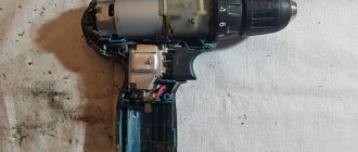
Disassembling the body of the electric drill takes a few minutes. The procedure consists of unscrewing 4–6 (depending on the model and brand) self-tapping screws. After this, the housing is separated into two halves, between which the engine and other mechanisms of the device are installed. If further disassembly is required, all available screws are sequentially unscrewed and the fastenings of the power cord, the “Start” button, and the reverse switch are released. The motor and gearbox are the last to be disconnected from the housing.
Proper disassembly begins with removing the housing cover and ends with removing the gearbox
When disassembling, it is important to remember not only the sequence of work, but also the exact location of the wires connecting the parts to each other.
Video: how to disassemble an electric drill
The drill does not turn on and does not work
If a drill connected to the network does not work when you press the “Start” button and does not show any signs of life, you need to check the following components.
- Power cord. First, the cable is visually inspected for breaks or fractures. If none are found, the second step is to check the cord with a multimeter or probe. To do this, the protective housing is removed. In some models, it is not necessary to unscrew the entire casing - it is enough to remove only the plastic handle protection. After access to the cord contacts is opened, the presence of voltage at the end of the wire is checked. On a working cord, the multimeter will show a voltage of 220 V. On the probe, when it touches the phase conductor, the red LED lights up.
It is more convenient to check the integrity of the cables and the presence of voltage in certain parts of the electrical circuit with a multimeter
- If the cord is in good condition, the voltage on the button and the electric motor is checked sequentially.
- Next, the operation of the capacitor and reverse switch is checked. Often a defect can be detected by careful inspection. The damaged part changes color or shape. For example, the plastic housing of the button, inside of which the microcircuit is located, often melts when overloaded for a long time. When you open the casing, this immediately catches your eye. Motor wiring breakdowns are also visible to the naked eye - often the cause of the failure is a broken cable or an interturn short circuit. The first is accompanied by burnt terminals or contacts, ruptures or sintering of conductors. The second is an unpleasant odor and blue spots on the windings. If the capacitor is damaged, it may become deformed and take on a barrel shape.
Disconnecting the electrical wiring contacts causes the drill to stop working.
The drill is cracking, but the chuck is not rotating
If the tool is equipped with an impact function, a characteristic cracking sound is produced by the toothed surfaces of the ratchet when friction occurs. The reason for this may be either a breakdown of the ratchet itself or jamming of the chuck, or rather, the shaft on which it is attached. To fix the problem, you need to disassemble the drill body to gain access to the gearbox. A careful inspection will help determine the cause of the problem and make the right decision. Often such symptoms accompany a seized bearing.
A drill that has been operated in conditions of high humidity and dust must be opened from time to time and the motor and bearings must be cleaned of dust. In addition, after removing dust and chips, the bearing must be lubricated. But in moderation - excess lubricant promotes the adhesion of small debris and ultimately leads to damage.
For prevention, the gearbox must be disassembled and lubricated.
Power button doesn't work
The “Start” button controls the operation of the drill. By pressing the trigger, the electric motor is started and its rotation speed is adjusted. As noted above, the internal structure of the start button is a triac (or thyristor) circuit printed on microfilm.
The button consists of several small parts: 1 start contacts, 2 engine speed controller, 3 electronic circuit, 4 rotation speed control wheel, 5 return spring of the button
It is impossible to disassemble and repair it at home. Therefore, if damaged, it is completely replaced. The button connection diagram is usually shown on the case in the form of a pictogram.
If the drill circuit does not use a capacitor, only two wires from the socket and two wires of the internal circuit are connected to the button. Otherwise, separate wires from the capacitor are suitable for it.
Depending on the type of electrical circuit, the button may have four to six wires.
Video: replacing the drill button
Soft start does not work
The soft start system of the electric motor is an important component in the tool circuit. All modern drills are equipped with this function. Thanks to it, the service life of the engine increases, the wear of rubbing parts in the engine is significantly reduced, and working with the drill becomes more comfortable. The main element of a soft start is a triac. If it burns out, the function stops working. The best option to fix the problem is to replace the entire button. But if this is not possible, you can replace the triac. To do this, you need to disassemble the button, remove the burnt part from the board and install a new one.
If you cannot find a new button, you can remove the board that controls the soft start function from it and replace the burnt triac in it
Before reassembling the button, the internal space is thoroughly purged and cleaned.
The speed controller does not work, its design and replacement
In addition to the soft start system, the drill is equipped with a manual speed control system. The wheel used to change the speed can be located on the button or elsewhere on the body. Modern models combine the soft start function and manual speed control in one electronic device, which was described above. The rotation speed is controlled by a variable resistor.
If the rotation speed control system is faulty and cannot be replaced, you can use an external device. For example, by turning on a dimmer in the power supply circuit. Or assemble the device yourself from inexpensive radio components.
The simplest dimmer for controlling the speed of an electric drill can be assembled from inexpensive and accessible radio components
Replacing brushes in a drill
Replacing graphite brushes in the electric motor commutator can be planned or emergency. Of course, the first option is preferable. Operation of excessively worn brushes leads to rapid wear of the commutator on the rotor. Following this, the motor may burn out. Brush depletion of more than 40% is a signal for a planned replacement. When the serviceability threshold is reached, the brushes begin to spark, and the sparking occurs so intensely that the housing heats up. It is impossible to bring the drill to this state.
Replacing brushes even in older models of electric drills is quite simple: access to them appears immediately after removing the protective casing
Different models have different methods for replacing brushes. But in most modern tools, a window is left on the body through which the brushes can be changed without disassembling the protective casing.
Video: replacing brushes in an electric drill
Drill reverse switch does not work
Beginner users often confuse the speed controller and the reverse of the drill. However, these are two different devices. And although they are located nearby, they are still enclosed in separate buildings. The operating principle of reverse (changing the direction of rotor movement) is quite simple. If you change the phase and zero on the brushes of the electric motor, the direction of rotation will change.
The reverse control mechanism is often located at the top of the button body
Please note that the reverse has 3 positions (not just 2). In one, the rotor rotates clockwise. In the other - counterclockwise. And the third position is neutral, in which the engine will not rotate at all.
If the reverse does not work, you need to remove it from the drill and disassemble the plastic case. In fact, the device consists of a simple contact switch, so there is nothing to break there. There may only be mechanical damage in the form of a broken shift lever or burnt copper contacts. In the latter case, the terminals are cleared and the device continues to function. Damage to plastic is more difficult to repair. It's easier to buy a new part and replace it. The reverse connection diagram is usually shown on its body. But it is better to remember (or sketch, photograph) the original location of the wires during the repair process.
The drill only rotates in one direction
Sometimes such a breakdown occurs - the drill does not obey the “orders” of the reverse switch and refuses to change the direction of rotation. To restore the function of the device, you need to open the switch cover and carefully inspect the internal mechanism. If the device has two operating positions, it is necessary to clean all contacts with fine sandpaper and check the degree of clamping of the terminals. If the contacts are not rigid enough, bend the copper plates. Before assembly, it is recommended to clean the inside of the plastic box from dust and other possible debris.
Bearing replacement
Mechanical failure of the bearing is accompanied by hum and vibration of the drill during operation. Wear occurs due to the ingress of large abrasive dust or chips into the protective casing, as well as due to overheating during operation and non-compliance with storage conditions. Bearings are especially sensitive to high humidity.
During factory assembly, the bearing is pressed onto the shaft
To replace it, you will have to completely disassemble the drill, disconnect the stator and remove the rotor on which the bearing is mounted. When assembled at the factory, it is pressed onto the shaft axis. Now it needs to be removed. The most reliable way is to use a special puller, with which the bearing comes off without distortion. You can knock it out by holding the anchor in a vice, but this must be done very carefully. An awkward movement can damage the rotor winding and then it will have to be completely replaced or rewinded.
The easiest way to remove the bearing from the rotation shaft is with a special tool
Video: replacing a bearing in a drill
How to check a drill armature with a multimeter and repair it
If the motor hums, but the chuck does not rotate at all or rotates very slowly, there is a high probability that the motor armature is damaged. This happens when the motor overheats, when the insulating varnish on the winding conductors melts and an interturn short circuit occurs. In order to carry out an absolutely accurate diagnosis, it is necessary to disassemble the tool casing and gain access to the armature windings and commutator. A multimeter sequentially measures the resistance of the frames in the winding. To do this, the probe of the device is installed on adjacent lamellas and the ohmmeter readings are recorded. If the values on any pair deviate from the norm, then there is a short circuit.
A multimeter is used to sequentially ring pairs of adjacent lamellas.
If earlier, in case of damage to the armature windings, craftsmen had to rewind them themselves, today practically no one does this. Especially when it comes to household appliances. On the power tool market, it is quite easy and without much damage to your wallet to purchase a damaged part and replace it yourself. In addition, it is quite difficult to guarantee quality when rewinding yourself. Not everyone can handle all the parameters. The smaller the drill, the more difficult it is to rewind the winding, since this requires special equipment.
Video: checking the armature of a commutator motor
How to ring the stator of an electric drill
The stator is checked in a similar way - using a multimeter. Compared to checking the anchor, the procedure is simpler and therefore faster. After all, there are fewer windings in the stator - usually 2 or 3 coils.
If a breakdown is detected in the coil, it is replaced. Rewinding at home is practiced only by enthusiasts of “crazy hands” and those who like to do everything themselves. To rewind, you need equipment in the form of a soldering iron and a template for correct placement of the conductor.
Video: how to check the armature and stator of an electric motor at home
The drill does not work at low speeds (the drill does not gain speed and gets hot)
The engine speed depends on the device discussed above - the electric motor speed controller. If the regulator malfunctions during operation, nothing can make the engine run faster or slower. Replacing the regulator is the only correct way out of an unpleasant situation.
There are cases when a speed violation occurs due to the fault of the gearbox. For example, a heavily clogged planetary gear can significantly reduce the rotation speed, especially if a large amount of oil-dried debris is “wound” around the axle. Broken large gear teeth and dirt on the worm gear also negatively affect the rotor speed. In this case, the engine will operate in overload mode, and this is fraught with overheating and, ultimately, interturn short circuits. Therefore, a simple conclusion suggests itself. The gearbox, like all other components of the mechanism, is subject to preventive maintenance and cleaning. It is usually recommended to carry out preventive maintenance at least once every two years, and in case of intensive use - every year.
Replacing the impact mechanism of a drill
If problems arise with the impact mechanism of the drill, the optimal solution is to replace the worn ratchet gear. The ratchet mechanism is directly connected to the gearbox, so in order to gain access to it, you will have to completely disassemble the drill. No other way to restore the ratchet has yet been invented. After replacing the gear, you should thoroughly clean the gear housing of old grease, as there are metal shavings left in it from the previous ratchet. New lubricant is added after assembly; its brand must correspond to the technical characteristics of the gearbox.
How to identify a faulty brush assembly
Drill brushes, which are a consumable item, fail. The brushes are made of graphite, and with their help, current is transferred to the rotor through the commutator unit. During operation, brushes wear out, burn out, wear out and require replacement. The service life of brushes depends on various factors:
- Quality
- Collector serviceability
- Power tool load
A brush malfunction can be identified by signs such as excessive sparking. If, before the drill stopped starting, there was excessive sparking with signs of carbon deposits, then it is highly likely that the carbon brushes need to be replaced. To replace, you need to remove the elements from the brush holders, remove the worn parts and install new ones in their place.
This is interesting!
If the brushes are worn more than 60% of the original length, they must be replaced.
In addition to the malfunction of the brushes, it is necessary to pay attention to the condition of the copper lamellas of the commutator. If there are signs of soot on the copper base, as well as chips and other defects, then all this should be eliminated. If you cannot fix it yourself, then you should replace the anchor. The cause of carbon deposits on copper plates is excessive sparking of the power tool. In addition, if the commutator is heavily worn, a connection (short circuit) between the plates occurs, which is also unacceptable.
General rules for repairing power tools
The safety rules for repairing an angle grinder are the same as for repairing any other power tool. Cleaning from dust, disassembling and assembling is carried out only with the device completely de-energized. Repair work must be carried out on a dielectric surface, and the power source must be equipped with a short circuit protection circuit breaker. It is strictly forbidden to manually turn the angle grinder spindle if the power supply is turned on. It is also prohibited to carry out test runs during or after repair with a cutting disc installed on the spindle.
If the electric motor is faulty, when should it be replaced?
The commutator-type electric motor on a drill and any other tool is the heart of the equipment, which costs 60% of the total cost of the device. If the malfunction is related to the electric motor, then there are two ways to repair the drill malfunction - replace the entire motor or carry out diagnostics, identify the malfunction and eliminate it. It should be noted right away that you can do the diagnostics yourself, but you won’t be able to fix the faults yourself. Here you will need to take the faulty unit to a specialized workshop, but practice shows that it is easier to buy a new rotor or stator than to repair them.
This is interesting!
It is also rational to take the engine in for repair when it is impossible to find spare parts for it.
Let's consider the principle of checking the serviceability of the stator and rotor of an electric drill motor with your own hands:
- Using a multimeter in resistance measurement mode, the value between the armature windings and the metal core is measured. The presence of resistance indicates a violation of the integrity of the insulation
- We use a marker to indicate the plate from which the check begins. Use the probes of the tool to touch the plates one by one and record the resistance value. In this case, the value between the plates should be approximately the same. A resistance difference of more than 10% is unacceptable and indicates the presence of a break
- Checking interturn short circuit. A special device can be used to measure the presence of an interturn short circuit. It makes no sense to buy such a device specifically, since if there is no breakdown of the insulation on the body or a short circuit between the plates, then with a high degree of probability it can be assumed that the armature is working
- After this, you should check the serviceability of the rotor. Similarly, the absence of resistance between the winding and the core is checked
- Check the resistance between the windings. The absence of resistance indicates complete damage to the winding, and if its value is large, a breakdown can be assumed. The video description below describes in detail how a step-by-step check of the serviceability of the commutator motor is carried out.
Malfunctions of the stator are less common than the rotor, but in any case, if the drill has recently been operating under high load, then the motor will fail. If it is determined that the motor on a drill is faulty, then it is easier to replace it than to repair it, and sometimes it is better to buy a new drill. The video below describes in detail how to find and fix electrical problems with a drill.
Triac regulator
The triac controller located in the start button is responsible for the speed of the installation when the drill is turned on. This regulator is mounted in the button body and is located on a lining made of textolite. The board is designed in such a way that it has small dimensions, which allows it to be completely located in the trigger space. After pressing the power button, an immediate break occurs in the device regulator, at which point the circuit is closed in a scanty period of time. And the regulator is not able to influence the voltage variation, however, the rms voltage level is subject to change.
After the drill starts operating, alternating voltage is supplied to the network.
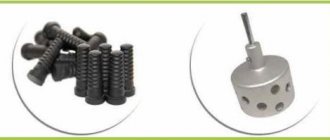
Figure 2. Drill spare parts.
In parallel with this, a sinusoidal voltage is supplied to the control electrode of the triac. During the period when its level is greater than the operating voltage of the triac, the latter opens, which indicates the circuit is closed; at this moment, current flows through the load.
The wiring diagram and connection of the installation button may differ in different models from different manufacturing plants. The most simplified of all the diagrams and the one that best shows the principle of operation is shown in Fig. 3. One wire from the power cord is connected to the speed controller. The presented figure shows the electrical circuit of the device, where “reg. rev." — speed regulator, “1st stage. exchange." — primary stator winding, “2nd st. winding.” - respectively, secondary, “1st brush.” - first brush.
In order not to get confused, it should be remembered that the speed controller and the reverse control system are represented by completely different components of the tool, which in some models even have separate housings.
Figure 3. Typical diagram of a drill speed controller.
Only 2 wires go to the speed controller. And the one that comes out of the speed controller is connected to the beginning of the stator primary. In the absence of reverse, the end of the primary would be mated to the rotor brush, and the second brush would be mated to the beginning of the stator secondary. The end of the secondary goes to the second wire of the cord, from which the drill is powered during operation.
The rotor begins to work in the other direction the moment the end of the primary is connected to the second brush. In the reverse system, such a connection is made; for this reason, the rotor brushes are interfaced with the stator windings through it. In Fig. Figure 4 shows a connection diagram for the reverse device. Wires in the amount of 4 pcs. go to the rotor brushes, those of them that are gray in color go to the end of the primary and the beginning of the secondary.
The system for adjusting the speed of the device involves the presence of a capacitor and the connection of wires that come from the outlet to the regulator. If we take into account the installation from the example, then only two contacts are used, which are located at the bottom. The system is completely devoid of a capacitor, and the second wire of the cord is connected directly to the stator winding.
An electric drill is one of the most common tools in the household. And it’s very bad when it suddenly stops working. In such cases, you really want to repair the drill yourself.
The design of a drill or hammer drill is quite simple. Different tool models mainly differ only in the differences in the arrangement of parts and the quality of their manufacture. The versatility of the operating principle and design used allows you to independently repair the drill in most cases of malfunctions.
Failure of the mechanical part of the instrument
If electrical faults are difficult to identify, then dealing with mechanical breakdowns is much easier and cheaper. Mechanical defects can be identified even without the need to disassemble the instrument. If the drill cracks or the chuck does not rotate, but the characteristic sound of the engine is heard, it means there is a breakdown in the gearbox. When the attachment does not hold in the drill, there is a malfunction in the clamping jaws. Bearings can also fail and cannot be repaired and require comprehensive replacement.
Let's consider each type of malfunction, and the features of their identification and subsequent elimination.
- The bearings have failed.
Typically, bearings last quite a long time, and the main reason for their rapid failure is the lack of lubrication or its depletion. There are two types of bearing failures: complete destruction of the balls or wear. If completely destroyed, the part must be replaced. There are no difficulties when replacing bearings, so be sure to check their serviceability - Jamming of the gear unit - here breakdowns are associated with licking of the driven or driving gear.
Even during operation, a tooth may break off, which will ultimately lead not only to a decrease in productivity, but also to a complete jamming of the transmission mechanism. If the gearbox malfunctions, the gears must be replaced. It should be taken into account that on household tools the gearbox can be made of plastic gears. They must be replaced with similar ones, otherwise installing metal gears will lead to accelerated engine wear. - Repairing the impact mechanism of a drill - unlike a hammer drill, this mechanism on a drill has a primitive design.
The design consists of two parts, reminiscent of a friction clutch. Impacts are created by the movement of a toothed gear. The notches on the rotating gear mesh with teeth of a similar design on the housing, and as if jumping, clicks are created - they are also impacts. Malfunctions of the impact mechanism of a drill include the following: licking of jagged edges, which ultimately leads to a decrease in productivity. More often, the notches are licked off on the moving gear, which needs to be replaced. Another breakdown can occur when the shock mode of the limiter is not turned off. The reason is the wear of the metal ball, which, when the switch is moved, goes into the end of the shaft, thereby limiting the possibility of the gear teeth coming into contact with the protrusions on the body. To eliminate the malfunction, you should replace the ball in the design of the impact mechanism - Malfunction of the actuator - cartridge.
Drills use key type chucks, which are characterized by increased reliability and efficiency. The clamping jaw on this part may fail and should be replaced. Detailed instructions on how to remove, repair and replace the chuck on a drill
Bearings and cartridges are considered minor mechanical failures, and failure requires an appropriate approach. Even if diagnostics have shown that the gearbox does not need repair or replacement of parts, it must be dismantled, washed in gasoline and new lubricant applied. Such manipulations must be performed regularly, depending on the frequency of use of the power tool. A detailed description of how to repair the impact mechanism of a drill is described in the video report.
How to replace brushes: work in a couple of minutes
But the drill may not work due to trivial faults - for example, due to brushes inside the motor. This means that you can’t do without repairing brushes, and this work is quite simple - you don’t even need to have special knowledge and tools. To do this, we disassemble the device, remove the brush holders from it and replace parts that are broken. By the way, there are models whose body does not need to be disassembled - you just need to remove special plugs through the installation window, after which we change the brushes.
You can purchase these parts at any hardware store; there are also some models that are sold together with a set of additional brushes
It is important that you do not wait until the brushes are completely worn out - check them from time to time. And all due to the fact that there is a risk of a gap forming between the bristles and the collector
As a result, this part will begin to overheat and eventually fall off - which means you will have to change the entire anchor, which will be much more expensive and more difficult, and it is not a fact that you will be able to solve this issue yourself.
As you can see, there are a variety of breakdowns, many of which will be within your control, others will only be possible for specialists in service centers. And to reduce the risk of such breakdowns, you need to take care of your tool, clean it after work, check the condition of the parts and brushes in order to replace them with new ones in time. However, if you see that you can’t handle it yourself, take the device to a workshop.
Learning to extend the life of a power tool from the moment of purchase
In order for the purchased power tool to serve for a long time and not fail at the most inopportune moment, it is necessary to ensure proper care from the very first day of purchase. This care includes doing the following:
- Store the tool exclusively in a dry and warm room. Exposure to moisture and low temperatures will lead to the formation of condensation and failure of the electrical parts of the tool.
- Do not use the tool for a long time under heavy loads, as this will lead to overheating of the windings and failure of the electric motor.
- The presence of an impact mode does not mean that you can drill holes in concrete and reinforced concrete with a drill every day. The impact drilling function is auxiliary and is intended for infrequent use. For such purposes it is necessary to use a hammer drill
- If the brushes spark strongly, it is necessary to replace them without waiting until the tool stops turning on altogether.
When purchasing, keep in mind that drills are available for household and professional purposes. If you choose a cheap household option, then you need to understand that such a tool is intended only for infrequent home use. Any repairs in the house using a household drill will cause the tool to fail. If you need a drill to make repairs in your home, then you need to choose only professional options.
Repairing a drill yourself is not at all difficult. The main thing is to approach this issue accordingly - start troubleshooting from small to large. After proper repair of a power tool, it will last for a very long time.
Electric drill motor start button
What a shame when something breaks at the most inopportune moment. Especially with current prices. For example, the start button of a drill often flies and at the same moment you wonder what flew this time? And then bam! Button! Infection! That's it, let's go buy a new one. But that's bad luck! We didn’t remember the location of the pins, what went where. And here the diagram will come in handy for you. Connection with 3-lead capacitor:
This also happens:
Reverse button:
In order for the engine to start working in the opposite direction, you need to swap the connections of the wires to the brushes (in a button with reverse, this is done using the switch lever). I would like to draw your attention when purchasing a button, it must match not only the size, but also the power of your drill. Let's do the math: we have a drill with a power of 650W, P=U*I, I=650/220=2.95A, . It turns out we need a button with U=~220V, I=at least 2.95A, which means the BUE-3~220V 3.0A button will suit us.
It turns out we need a button with U=~220V, I=at least 2.95A, which means the BUE-3~220V 3.0A button will suit us.
thoughts on “Drill DWT SBM-500 VS Replacing the power button”
This button is built on a triac, so you can’t simply check it with a device, as you show, in my case with such a drill it doesn’t ring when pressed, but the drill works, i.e. works without pressing a button, when plugged into a power outlet
Thank you. Everything was really explained clearly. I fixed the drill. By the way, what can you say about these drills? Reliable?
Hello, how to connect directly, without a button? Thank you.
All clear. of course!! Respect to Aftor!! But – very poor lighting. This must be taken into account! And a pin is not an option at all – it gets stuck at the contact point!! You need a flat mini screwdriver!!
Thank you for the video. The reverse burnt out, everything inside was a mess. I wanted to close it at random... But here it turns out to be diagonal. I threw out the reverse. closed directly. Works great.
My button stopped working, I took it apart and saw that in addition to the speed control board, there are 2 movable contacts, one turns on the power through the voltage regulator and the second connects the power directly, supplying 220 volts to the drill motor, so a thyristor (or triac) fell off on the board, soldered it - it worked. a year later there was another breakdown, the drill stopped working at low speeds, I again disassembled the button - this time one of the two moving contacts broke off or was worn away (they play the role of a variable speed control resistance and move along with pressing the trigger of the switch, because of this the drill only turned on at high speeds with the second moving contact) and it can no longer be done. And I decided to make a compact power regulator with a remote potentiometer, everything is put into a socket on an extension cord and it works with a bang. We adjust it like a dimmer at 500 wt/ And the drill goes straight to full power if you turn it on directly at 220.
Tell me, drill Interskol DU-13/750ER, in the button one contact from the power cord is clamped with a bolt, the second one they say needs to be pressed out using an awl / needle, I’m trying to do this with a needle, but I need something thicker, or I need to know where insert this needle, because for some reason I only managed to pull the wire out a couple of millimeters, and then very tightly... Could you tell me how to do this correctly?
Motor fault
Electric motor failure is the second most common cause of drill malfunction. This is due to damage to the stator or armature winding. Such damage occurs due to a manufacturing defect in the windings or improper operation of the drill (long-term operation without breaks, load exceeding the permissible when the drill jams, etc.). As a rule, electrical breakdown of the winding is easily determined visually or by the characteristic burning smell. If there are no visible manifestations, then the motor windings should be checked with a tester, ohmmeter and megger for resistance value. There may be three types of wire damage: a short circuit between turns, a breakdown of a turn to the body, or a wire break. Repair of the stator or armature is not carried out independently.
To replace the elements of the electric motor, the drill body is disassembled, the contact brushes and supply wires are disconnected, and the electric motor is removed along with the support bearings.
If necessary, remove the drive gear. The faulty electric motor element is disconnected and replaced with a new one, or the old one is installed after repair (rewinding) by professionals.
Return to contents