A thread drill is a metal-cutting tool that is used before using a tap or similar device. It is necessary that all parameters comply with current requirements and standards. Otherwise, the fastening will be unreliable.
To select the optimal drill diameter for threads, special tables have been developed. The value depends on the type of cut. Requirements for drill size and metric hole parameters are regulated by the interstate standard GOST 19257-73. As an auxiliary tool, it is necessary to use a caliper or other device to calculate the size and pitch of the thread.
Hole parameters
Threads are distinguished according to the following characteristics:
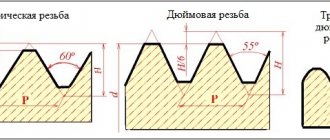
- Unit of measurement. Throughout the country, the metric system is predominantly used. Inch values were used in the pipe industry.
Abroad, the inch system is considered the main one. Owners of cars that were assembled for the American market know that there is not a single element with metric cutting.
- Thread pitch and number of thread starts. Non-standard parameters are used in the automotive and machine tool industries.
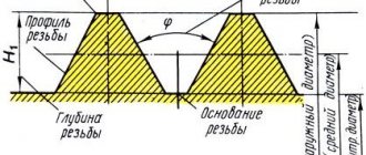
- Profile form. The figures differ in the type of cutting. There are elements of triangular, rectangular, trapezoidal and round shapes.
- Direction of turns. There are right- and left-handed cuts.
- View. External or internal.
- Surface type. It can be cylindrical or conical.
The main condition for a high-quality connection is the correspondence of the indicators of the external and internal threads. If one of the parameters does not match, the fastening will be unreliable.
The most common threaded connection methods are bolt and stud fasteners. In the latter case, in addition to the main device, nuts and washers are used as auxiliary elements.
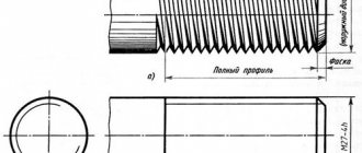
Pre-drilling holes is an essential procedure prior to cutting. In this case, the diameter of the gimlet should be slightly smaller than the size of the bolt or stud.
Drilling depth is one of the most important indicators. When calculating, the following factors must be taken into account:
- screw-in depth of the threaded element;
- the size of the external thread;
- presence and chamfer parameters.
To calculate the screw depth, the type of material being processed must be taken into account. For steel, titanium, bronze and brass no corrections are needed, but for gray and ductile cast iron a multiplying factor of 1.25 is used. For light alloys this figure is even higher - it is doubled.
Device Features
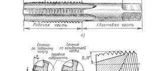
At first, a three- or four-sided rod was used, on which the teeth were cut. The end was sharpened into a shallow cone. When screwing such an artifact into the hole of a nut or body, toothed bridges cut an internal thread. It is clear that such a tool was far from perfect, since the cutting teeth did not have a back angle, and the front angle was negative. However, its design was gradually improved until it became more rational. Today, any tap for threading has similar design elements:
- Grooves for the release of chips and the supply of cooling and lubricating fluid (coolant). Their number is usually from 2 to 6 .
- The profile of the depressions can be different: single-radius, straight front and rear surfaces, straight front and radius rear.
- Groove direction: straight, spiral right and left . The former are used in conventional universal taps. Flutes with a left-handed helical line are used to cut threads for passage. In this case, the chips go in front of the tap so as not to spoil the cutting. Right-hand recesses are used for blind holes so that the chips are brought back, otherwise they, being compressed, will break the tool.
- The intake part is made conical in order to facilitate cutting of the cutting teeth into the material of the part . The tilt angle is from 3 to 20 degrees, depending on the purpose of the tap (roughing, intermediate, finishing).
- The calibrating part is cylindrical, has a reverse lowering of up to 0.1 mm, which serves to reduce the friction force . For the same purpose, the calibrating teeth are backed at a distance of 1/3 of the width of the feather from the top of the tooth. The reduction is about one tenth of a millimeter for threads with a diameter of 12 to 30 mm.
Drill and hole size chart for metric and inch threads
Let's consider the calculation results from GOST 19257-73:
- For M3 threads, a tap is required, for which the standard pitch is 0.5, drills are 2.5 mm.
- For M4 threads, a tap is required, for which the standard pitch is 0.7, drill bits are 3.3 mm.
- For M5 threads, a tap is required, for which the standard pitch is 0.8, drill bits are 4.2 mm.
- For M6 threads, a tap is required, for which the standard pitch is 1.0, drill bits are 5.0 mm.
- For M8 threads, a tap is required, for which the standard pitch is 1.25, drill bits are 6.75 mm.
- For M10 threads, a tap is required, for which the standard pitch is 1.5, drills are 8.5 mm.
- For M12 threads, a tap is required, for which the standard pitch is 1.75, drill bits are 10.25 mm.
- For M16 threads, a tap is required, for which the standard pitch is 2.0, drills are 13.5 mm.
Despite the fact that the metric system is the most popular, we recommend that you familiarize yourself with the table of threaded drill diameters:
Buy a screw thread set from AliExpress from 105 rubles →
Drilling tool selection formula
Selecting the optimal drill size for threading is the key to high-quality operation of the threading device.
The easiest way to calculate is to use the well-known formula: the step size is subtracted from the nominal diameter. For example, for M8 you need a device with a cross section of 8-1.25 (standard pitch) = 6.75 mm.
It should be remembered that when working with plastic materials, the calculated number of turns increases. Thus, to drill into brass, it is necessary to prepare a gimlet with a larger diameter than is necessary for brittle metals and alloys such as cast iron or bronze.
As practice shows, the hole diameter should be smaller than the nominal thread size. At the same time, there are limit values, exceeding which is considered a violation of the technological process. For example, for M6, the maximum hole diameter should not exceed 5.153 mm.
Types and areas of application of taps
According to the drive method, they are divided into:
- Manual - they have a square tail, which is inserted into the knob. There are two handles that make it convenient to turn the product. It is important not to allow distortion. This result can only be corrected by drilling and cutting a larger diameter.
- Machine - used on metal-cutting machines. They are firmly fixed in the holder, accurate, and do not allow deviations.
By cutting method:
- Universal. Their design can be called classic. A tool with a running gear (its length determines the depth of insertion of the screw later if the hole is not through), which is divided into sections. Each of them has certain geometric parameters - angle, direction, distance, step. There are usually three of them, each designed for rough metalworking, intermediate and finishing. Thus, you can achieve the most accurate result with one movement.
- Complete. The name speaks for itself. You will need a set of 3 taps, since the internal thread must be made with high precision. First, the coarsest tool is used, then a finer one, and finally - with grinding and sharpening of the smallest corners. Buying a set is more expensive, but the result is much higher quality.
By hole type:
- For through. They are distinguished by a long working part. It gradually expands, moving into the working area, which is responsible for precise cutting.
- For the deaf. On the cutting section, calibrating turns immediately begin. Therefore, it is very important to sharpen them or promptly change the set as they wear out.
According to the groove design:
- straight – I work well with soft alloys;
- screw, their working area is staggered, they can easily pass even through cast iron;
- shortened - removes chips well.
The shape of the product resembles a cone (full or truncated) or a cylinder. They also all differ in diameter.
Which drill is better to use
Modern industry offers consumers a wide selection of devices for processing various surfaces. The following metal drills are available:
- Spiral. The most common type. It is a cylindrical tool made of high quality materials. High-speed steel is most often used. The maximum diameter of the gimlet can reach 80 mm. They are used in large metalworking enterprises.
- Stepped. They have the shape of an expanding drill. They should not be used as a preparation tool before using the tap. The main area of use is processing of thin sheet metal.
- Feathers. A universal tool. A special feature is the presence of removable cutting plates. With their help you can get a perfectly shaped hole. Feather drills are a relatively inexpensive tool. They are rarely used for drilling holes for threading. The main scope of application is the correction of defects and distortions.
- Elongated. This design allows you to make blind or through holes at significant depths. The operation of such devices involves the use of cutting fluid, which is supplied through special channels. In industrial enterprises, gimlets are used to process superhard materials.
- Centering. Refers to turning devices. Used for drilling holes to further secure the workpiece in the centers.
It is necessary to pay attention to the accuracy class. The cleanliness of the finished hole depends on this parameter. There are three accuracy classes:
- "IN". Lowest class. Allows you to design holes with an accuracy of 15 grades.
- "IN 1". High purity tool. The accuracy indicator is up to 14th grade.
- "A". High precision device. Allows you to make holes in the range of 10–13 quality. They are distinguished by their high cost.
Selecting the correct drill size for making a hole before cutting a thread is an important procedure, the quality of which determines the reliability of the future connection.
Do you use a selection formula or prefer to be guided by auxiliary tables? Write about your method in the comments block.
Types by purpose
Modern industry produces various types of taps, which differ from each other in design and functionality. Thus, according to their purpose, taps can belong to one of the following types.
Locksmith
These tools are most often hand-held and are used in conjunction with a special crank, with the help of which rotation is imparted to the tap. As a rule, they are produced and used in sets consisting of two or three tools, each of which removes only part of the allowance from the surface being processed. The dimensions of the taps included in this kit (in particular, their working diameters) vary. The first of the tools, on the shank of which is marked in the form of one line, is used for roughing, the second (with two lines on the shank) is used for intermediate processing, and the third (with three lines, respectively) is used for finishing the thread being cut.
Complete hand taps
Machine or machine-hand
These are tools with which threads can be cut both manually and on various types of machines (lathes, drills, aggregates, etc.). Such taps differ from metalwork taps only in that they have a slightly shorter fence part and higher resistance to mechanical loads.
Machine-manual triple taps
Nuts
With the help of such tools, as their name suggests, they cut threads in nuts. Nuts, which have already been threaded with such a tap, are not twisted from the tool, but are moved to its elongated tail part. The shanks of nut taps, with which threads are cut on drilling machines, have a rectilinear shape. Nuts with already cut threads, moved to such a shank, are simply shaken off it after removing the tool from the machine chuck. To cut nuts, automatic threading machines use taps whose shanks have a curved shape. When carving in this way, the nuts, under the pressure of each other, are pushed along the curved shank of the tool, reach its end part and fall into the prepared container.
Tapping threads with a nut tap
Requirements for the design and dimensions of both manual and machine taps for cutting metric threads are specified by GOST 3266-81, which is called: “Machine and hand taps. Design and dimensions."
You can familiarize yourself with the GOST requirements for manual and machine taps by downloading the document in pdf format from the link below.
GOST 3266-81 Machine and hand taps. Design and dimensions