In the manufacture of almost any radio crafts, resistors are used. I think there is no need to explain what it is and how it works, and the purpose of this article is somewhat different. I would like to focus on the standard sizes of SMD resistors, and in addition to indicating the dimensions, mention their designation, that is, markings and power dissipation. All these are important parameters, because how do you know what to order for a project, and besides, be sure that the transistor will withstand the current passing through it. Well, this is where the introduction ends and the substance of the material begins.
Let's immediately turn to the table; it seems to me that this is the most valuable material.
What is the marking of smd resistors
SMD resistors are permanent parts that are required for surface mounting on a board. If we compare smd resistors and metal film resistors, the former will be several times smaller, but there are also those that are larger, which is why there is a marking of smd resistors. They also differ in shape; there are square, rectangular and round and even oval. Carefully studying the SMD resistor markings, you can note that the markings can be digital or alphabetic.
The main difference between SMD resistors is the presence of small contacts that are inserted into the printed circuit board. Let's look at why resistor markings are needed.
Why do we need resistor markings?
Considering the fact that SMD resistors are small in size, they cannot be color coded, so manufacturers have developed a different marking method. As a rule, the designation of smd resistors contains three or four numbers; letters may be present.
- Digital marking of resistors is necessary in order to indicate the numerical value of the resistance of the resistor, the last digit is a multiplier. It can also indicate the power that must be raised to 10 to get the final result. For example, resistance can be determined this way: 450 = 45 x 10 equals 45 Ohms.
- If the marking is EIA-96, then this means that the resistors are high precision. This standard is intended for resistors that have a small resistance of 1%. This marking system has three elements: 2 numbers that indicate the denomination code, and the letters are a multiplier. The numbers are a code that gives the resistance number. For example, code 04 may indicate 107 ohms.
For convenient calculation, a calculator is used that will help you quickly find the resistance value. To calculate, you need to enter the code that is on the component and the resistance will immediately appear below. This calculator is suitable not only for the standard. To more accurately check the resistance, it is best to use a multimeter for calculations. Read here which is the best multimeter to choose.
What characteristics does it show?
The most important characteristics of the parts are the value of the nominal resistance, the tolerance on the value and the temperature coefficient. Any of these characteristics is related to the power of SMD resistors and the resistance between it and the ambient temperature. In some areas, even noise characteristics are taken into account.
Important! Component characteristics include stability, voltage, resistance dependence and frequency parameters.
To understand this issue in detail, you need to carefully study all the characteristics:
- The value of the nominal resistance. The tolerance on the nominal resistance value is specified as a percentage. This value indicates the resistance of the resistor under external influences on it.
- Temperature. As a rule, the natural temperature is +20°C and there should be normal atmospheric pressure. SMD resistors are produced with a tolerance for nominal resistance ranging from ±0.05% to ±5%.
- Accuracy. The most accurate resistors can be considered those that are calculated using the formula TKS=DR/(R*DT). DR means the change in resistance when the temperature changes by the amount DT, R is the nominal value of the resistance.
If the components can be calculated using this formula, then this means that they have the highest accuracy.
Thermistors
Rice. 6. Thermistor
Thermistors are resistors whose resistance changes significantly with temperature changes (Fig. 6).
The resistance of NTC thermistors gradually decreases with increasing temperature. NTC are ready-made temperature sensors with a measurement range of -55… +200°C.
PTC thermistors are characterized by an abrupt change in resistance at a certain temperature. They are used as overcurrent protection elements.
PTC hold current is the current at which the thermistor is guaranteed to be conducting.
PTC trip current is the current at which the thermistor is guaranteed to become non-conducting.
Examples
- PTC thermistors:
- 1812 - MF-MSMF series manufactured by Bourns for operating currents from 0.3...5.2 A;
- 1812 - 1812L series from Littelfuse for operating currents 0.1...3.5 A.
- B57236 series from EPCOS with a resistance range of 2.5...120 Ohm;
- 0603 - ERT-J1 series from Panasonic with a resistance range of 0.022...150 kOhm.
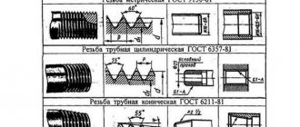
Types of SMD resistor markings
An important characteristic of resistors is the size. In simple words, this is the size, length and width of the body. It is by taking these elements into account that it is possible to select the appropriate board layout.
Reference! All sizes of SMD resistors in the documentation are indicated using special numbers and letters. The first numbers can indicate the dimensions, which are given in millimeters, the second pair of characters can indicate the width, also in millimeters.
Let's look at some typical resistor sizes and their decoding by numbers:
- SMD resistors 0201: length = 0.6 mm, width = 0.3 mm, height = 0.23 mm. The nominal values are 0 Ohm, 1 Ohm - 30 MOhm. Power is only 0.05 W, voltage maximum 50 V.
- SMD resistors 0402: length = 1.0 mm, width = 0.5 mm, height = 0.35 mm. The nominal values are 0 Ohm, 1 Ohm - 30 MOhm. Power is only 0.05 W, voltage maximum 100 V.
- SMD resistors 0603: length = 1.6 mm, width = 0.8 mm, height = 0.45 mm. The nominal values are 0 Ohm, 1 Ohm - 30 MOhm. Power is only 0.01 W, voltage maximum 100 V.
- SMD resistors 0805: length = 2.0 mm, width = 1.2 mm, height = 0.4 mm. The nominal values are 0 Ohm, 1 Ohm - 30 MOhm. Power is only 0.125 W, voltage maximum 200 V.
- SMD resistors 1206: length = 3.2 mm, width = 1.6 mm, height = 0.5 mm. The nominal values are 0 Ohm, 1 Ohm - 30 MOhm. Power is only 0.25 W, voltage maximum 400 V.
- SMD resistors 2010: length = 5.0 mm, width = 2.5 mm, height = 0.55 mm. The nominal values are 0 Ohm, 1 Ohm - 30 MOhm. Power is only 0.75 W, voltage maximum 200 V.
- SMD resistors 2512: length = 6.35 mm, width = 3.2 mm, height = 0.55 mm. The nominal values are 0 Ohm, 1 Ohm - 30 MOhm. Power is only 1 W, voltage maximum 400V.
Examples of decoding digital markings of SMD resistors
To quickly understand the decoding of SMD resistor markings, you need to consider several options.
Resistor 103
To calculate resistance, it is worth understanding the numbers from the very beginning. If we take resistor 103, then the first two digits will indicate the numbers, and the third digit will be the number of zeros, so it turns out that 10 and 3 will be 10,000 ohms. Such components may have a small error, which ranges from 2 to 10%.
Resistor 1206
In this case, the resistance is calculated in a different way. The first three digits are the number, and the last number of zeros or, as they say, the power to which the factor 10 must be raised. So, let’s calculate the value of the element with characteristic 1206:
120 * 10 to the 6th power = 2.985984 × 10^12 kOhm with an error of 1%
Resistor 2r2
If the component has a fractional value, then the letter R is placed in the code instead of a dot. In this case, the calculation for the resistor is 2R2 = 2.2 Ohm.
The most difficult thing to calculate is alphabetic and numeric codes, since numbers contain one information, and letters act as a multiplier. For quick calculations, there are special online calculators that help determine the resistance of an SMD resistor. There is also a marking table that is useful in calculations.
Internal structure
The main load-bearing element of the resistor is a substrate made of aluminum oxide (Al2O3). This material has good dielectric properties, but in addition it has very high thermal conductivity, which is necessary to remove the heat generated in the resistive layer into the environment.
Internal structure of the resistor.
The main (but not all) electrical characteristics of a resistor are determined by the resistive element, which is most often a film of metal or oxide, for example, pure chromium or ruthenium dioxide, deposited on a substrate.
The composition, technology of application to the substrate and the nature of processing of this film are the most important elements that determine the characteristics of the resistor, and most often represent the manufacturing secret of the manufacturer.
Some types - wire resistors - use thin (up to 10 microns) wire made of a material with a low temperature coefficient of resistance (for example, constantan) wound on a substrate as a resistive material. In the latter case, the resistor value usually does not exceed 100 Ohms.
To connect the resistive element to the conductors of the printed circuit board, several layers of contact elements are used. The inner contact layer is usually made of silver or palladium, the intermediate layer is a thin film of nickel, and the outer layer is lead-tin solder.
This complex contact structure is designed to ensure reliable mutual adhesion of the layers. Its characteristics, such as reliability and current noise, depend on the quality of the contact elements of the resistor. The last element of the SMD resistor design is a protective layer, which ensures the protection of all elements of the resistor structure from the effects of environmental factors, and primarily from moisture. This layer is made of glass or polymer materials.
SMD resistor marking table (code/nominal/size/power) table
SMD resistors marking table:
| Code | Nominal, W | Size | Power V |
| 0402 | 0.062 | Length 1.0 ±0.1, width 0.5 ±0.05, height 0.35 ±0.05 | 100 |
| 0603 | 0.1 | Length 1.6 ±0.1 width 0.85 ±0.1 height 0.45 ±0.05 | 100 |
| 0805 | 0.125 | Length 2.1±0.1 width 1.3 ±0.1 height0.5 ±0.05 | 200 |
| 1206 | 0.25 | Length 3.1 ±0.1 width1.6 ±0.1 height0.55 ±0.05 | 400 |
| 1210 | 0.33 | Length 3.1 ±0.1 width 2.6 ±0.1 height0.55 ±0.05 | 400 |
| 2010 | 0.75 | Length 5.0 ±0.1 width 2.5 ±0.1 height 0.55 ±0.05 | 400 |
| 2512 | 1 | Length 6.35 ±0.1 width 3.2 ±0.1 height 0.55 ±0.05 | 400 |
| 0075 | 0,02 | Length 0.3 Width 0.15 | 100 |
| 01005 | 0,03 | Length 0.4 Width 0.2 | 100 |
| 0201 | 0,05 | Length 0.6 Width 0.3 | 100 |
| 1218 | 1 ; 1,5 | Length 3.2 Width 4.8 | 150 |
| 1812 | 0,5; 0,75 | Length 4.5 Width 3.2 | 200 |
Today there are a huge number of highly specialized parts that differ in their advantages and disadvantages. For example, there are capacitors that can operate at high temperatures, almost 230 °C, there are those that are designed to work in aggressive environments, and milliohm chip resistors have also appeared. There are capacitors that can only be used in certain circuits. The table above indicates standard options, but actual power dissipation may vary.
Main parameters of tantalum capacitors
To determine a safe operating mode, it is necessary to calculate the levels of permitted current and voltage values. For calculations, you need to know the following parameters of tantalum capacitors, which are reflected in the documentation:
- Nominal capacity.
These devices have high specific capacitance, which can be thousands of microfarads. - Rated voltage.
Modern models of these devices are mostly designed for voltages up to 75 V. Moreover, for normal operation in an electrical circuit, the part must be used at voltages that are less than the nominal one. Operating tantalum capacitors at voltages up to 50% of the rated voltage reduces the failure rate to 5%. - Impedance (total resistance).
Contains inductive component, parallel resistance, series equivalent resistance (ESR). - Maximum power dissipation.
When AC voltage is applied to a tantalum device, heat is generated. The permissible increase in the temperature of the capacitor due to the released power is established experimentally.