In this article we will tell you what electrical power is and how it can be calculated.
Definition.
Electric current power (denoted by the letter P) is a physical quantity defined as the amount of work done by a source of electrical voltage to transfer electric charge (q) along a conductor per unit time t.
Generally speaking, the power of an electric current shows how much electrical energy is converted in a certain time. It also describes the consumer’s energy consumption.
Electrical current through voltage and current
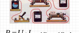
Since the potential difference calculated by the formula (F1-F2) determines the voltage (U), it is easy to conclude that the relationship established by Ohm’s law cannot be used. Electrical power (P) is also qualified by the current strength (I) on a specific section of the line. Final expression: P = U x I.
What is the load determined in terms of current and resistance?
Through a simple conversion, the electrical energy consumption is determined using the following formula: P = I2 x R. This shows the dependence of the power on the nominal value of the resistor connected to the line of the network element. For a complete circuit, the source resistance (internal) and the conductance of the connection point are indicated.
Joule-Lenz law
In the case when no mechanical work is performed on a section of the circuit, and the current does not produce chemical effects, only heating of the conductor occurs. A heated conductor gives off heat to surrounding bodies.
The law determining the amount of heat that a current-carrying conductor releases into the environment was first established experimentally by the English scientist D. Joule (1818-1889) and the Russian E.H. Lentz (1804-1865). The Joule-Lenz law is formulated as follows:
Joule-Lenz law
The amount of heat generated by a current-carrying conductor is equal to the product of the square of the current, the resistance of the conductor and the time the current passes through the conductor.
Q=I2RΔt
The amount of heat is measured in Joules (J).
Example No. 2. Determine how much heat was released in 2 minutes by a conductor at a voltage of 12 V and a resistance of 2 Ohms.
We use Ohm's law and the Joule-Lenz law:
Q=I2RΔt=(UR..)2Δt=U2R..Δt=1222..=72 (J)
What is it and how to calculate the load
Electric current load is a quantity characterizing its properties. Shows how much energy is consumed by electrical appliances. The current power is measured using a special device - a wattmeter.
If you connect a meter in series, you can check the current strength. When connecting in parallel, the voltage is determined. The amount of circuit consumption is calculated using the formulas: P = I x U or P = U2/ R = I2 x R.
The electrical load is equal to the voltage across the consumer multiplied by the amount of current flowing through it.
P = U x I
The formula indicates which measurements determine this parameter. If the load is active, it is measured in Watts, the reactive unit of electrical power is VA.
Reactive unit of electrical power - VA Source infourok.ru
Current measuring instruments
Electrical measuring instruments are a special type of devices that are used to measure many electrical quantities. These include:
- AC ammeter;
- AC voltmeter;
- Ohmmeter;
- Multimeter;
- Frequency meter;
- Electric meters.
Ammeter
To determine the current strength in an electrical circuit, you need to use an ammeter. This device is connected to the circuit in series and, due to its negligible internal resistance, does not affect its state. The ammeter scale is graduated in amperes.
In a classic device, a measured current passes through an electromagnetic coil, which creates a magnetic field that causes the magnetic needle to deflect. The deflection angle is directly proportional to the measured current.
Classic ammeter
An electrodynamic ammeter has a more complex operating principle. It contains two coils: one is movable, the other stands still. They can be connected to each other in series or in parallel. When current passes through the coils, their magnetic fields begin to interact, which as a result causes the moving coil with an arrow attached to it to deviate by a certain angle proportional to the magnitude of the current being measured.
Voltmeter
A voltmeter is used to determine the voltage (potential difference) across a section of the circuit. The device must be connected parallel to the circuit and have high internal resistance. Then only hundredths of the current will enter the device.
School voltmeter
The principle of operation is that inside the voltmeter there is a coil and a series-connected resistor with a resistance of at least 1 kOhm, on which the volt scale is calibrated. The most interesting thing is that the resistor actually registers the current strength. However, the divisions are selected in such a way that the readings correspond to the voltage value.
Ohmmeter
This device is used to determine electrically active resistance. The principle of operation is to change the measured resistance into a voltage directly dependent on it thanks to an operational amplifier. The desired object must be connected to a feedback circuit or to an amplifier.
If the ohmmeter is electronic, then it will work on the principle of measuring the current flowing through the required resistance at a constant potential difference. All elements are connected in series. In this case, the current strength will have the following dependence:
I = U/(r0 + rx),
where U is the emf of the source, r0 is the resistance of the ammeter, rx is the desired resistance. According to this dependence, resistance is determined.
Electronic ohmmeter
Multimeter
The devices given as an example are used today only in schools for physics lessons. Multimeters were invented for professional tasks. The most common device includes simultaneously the functions of an ammeter, voltmeter and ohmmeter. The device can be either easily portable or huge stationary with a large number of possibilities. The name “multimeter” was first applied specifically to a digital meter. Analog devices are more often called “avometer”, “tester” or simply “Tseshka”.
Universal multimeter
The work of current is a complex but very important topic in electrodynamics. Without knowing it, you will not be able to solve even the simplest problems. Even electricians use job finding formulas to make the necessary calculations.
How to determine the maximum current load
The useful power shows the maximum value in a situation where the load resistance R is compared with the same parameter inside the source - r.
R = r.
P max = E2 / 4r, where E is the driving force of the current source.
To calculate the maximum current load for an electrical device, you need to know the rated load parameter and the AC input voltage. The technical data sheet of the device, manual or emblem contains the first indicator.
For example, when the appliance rating (P) is 12 W, the maximum current consumption at AC voltage will be for:
- 120 V – I = 12/120 = 0.100 A or 100 mA.
- 220 V – I = 12 / 220 = 0.055A or 55 mA.
If necessary, the amount of electricity consumed is expressed through a complex value. For this purpose, basic relationships are used, impedance is used instead of resistance.
Questions and tasks for self-control
- Write the Joule-Lenz law in integral and differential forms.
- What is short circuit current?
- What is gross power?
- How is efficiency calculated? current source?
- Prove that the greatest useful power is released when the external and internal resistances of the circuit are equal.
- Is it true that the power released in the internal part of the circuit is constant for a given source?
- A voltmeter was connected to the flashlight battery terminals, which showed 3.5 V.
- Then the voltmeter was disconnected and a lamp was connected in its place, on the base of which it was written: P = 30 W, U = 3.5 V. The lamp did not burn.
- Explain the phenomenon.
- When the battery is alternately shorted to resistances R1 and R2, an equal amount of heat is released in them at the same time. Determine the internal resistance of the battery.
Electrical Appliances Parameters
Every modern apartment must be equipped with electrical appliances. To connect them to the network, it is necessary to draw up a schematic diagram where the loads connected to individual lines will be distributed in coordination with each other. It is necessary to build in a circuit breaker based on the PUE to prevent emergency situations.
First, the electrical wiring parameters are clarified. Then they are checked according to the group diagram for connecting to the network of household electrical appliances.
Standard characteristics of electrical power consumption (W):
- desktop computer – 170-1,250;
- LCD TV – 120 – 265;
- laptop – 40-280;
- air conditioning – 1,200 – 2,500;
- iron – 450-1850.
To protect the network, you need an automatic machine; we choose it taking into account all the significant factors.
Automatic switch for protecting the electrical network Source vmasshtabe.ru
It is important to pay attention to loads that have increased reactive energy parameters.
What is it measured in?
The unit of measurement of electrical power is W for Russia. By international standards - W. This is the energy provided per unit of time. One W is equal to a joule per second (J/s). Moreover, a joule is a unit of electrical power, a second is a unit of time.
For small values, multiple prefixes are used: “milli-”, “micro-”, for large values - “mega-”. For example: 5,800 W = 5.8 kilowatts = 5.8 kW.
When you multiply 1 Kilowatt by 1 hour, you get a Kilowatt-hour (kW x h). This is a unit of measurement of the amount of electricity provided to subscribers. It is used by energy enterprises that own the appropriate equipment (generators and transformer substations). They generate and convert the produced electricity, which is then distributed to consumers.
In the same way, the energy capacity of batteries is measured in units of ampere hours (Ah). Portable types of energy storage batteries are measured in milliampere hours (mAh).
The energy in batteries is measured in milliamp hours (mAh). Source listtopa.ru
For the unit of measurement Watt, according to international standards, the letter designation W is allocated after James Watt. He was the first to use the term “horsepower,” which today is an obsolete unit of the W parameter.
Energy conversion indicators:
- horsepower (HP) - 746 W;
- kilo Watts (kW) – 1×1000 W;
- megawatts (MW) −1×1000000 W;
- gigawatt (GW) – 1×1000000000 W.
Today, "horsepower" is used to indicate the second measure of engine power in vehicles.
What determines the load of electric current?
Existing electrical wiring lines experience resistance during the movement of electrons, which characterizes voltage loss. Circuits where an alternating current source is present have one feature - the key role here is played by a sinusoidal oscillation of electrical indicators.
Sinusoidal oscillation of electrical indicators. Source urpsvet.ru
The following information will allow you to select the best calculation method based on actual network conditions.
Types of capacities
Power is a measured physical quantity that is equal to the rate of change with the conversion, transmission or consumption of system energy. According to a narrower concept, this is an indicator that is equal to the ratio of time spent on work to the period itself spent on work. In mechanics it is designated by the symbol N. In electrical engineering the letter P is used. You can often also see the symbol W, from the word watt.
AC power is the product of current, voltage and cosine of the phase shift. In this case, only the active and reactive varieties can be easily counted. You can find out the full power value through the vector dependence of these indicators and area.
Main power types.
Instantaneous electrical power: calculating the value
This indicator establishes the instantaneous values of the measured data. The key definition is considered taking into account the fact that a single simple charge (q) moves in a certain time Δt. To perform a specific action, the energy of electric current PF1-F2 = U/ Δt or (U/ Δt) x q = U x (q/ Δt) is expended. The formula takes into account the movement of q over the period Δt. Since the current, according to the classical definition, is equal to the charge moving from F1 to F2 (I = q/ Δt), the final expression is derived: PF1-F2 = U x I.
Conditionally assuming that the time period is very short, we obtain the instantaneous power for part of the electrical circuit P(t) = U(t) x I(t). The same conclusions can be drawn taking into account the corresponding resistance parameter: P (t) = (I (t))2 x R = (U(t))2/ R.
Electrical power: DC circuit
The previously mentioned formulas are shown without correction factors. They are used to calculate a circuit connected to a direct current source. Using an ordinary device - a multimeter, with the switch in the correct position, the resistance of the load connected to the network is set.
With its help, the load resistance is set. Source hammer-shop.ru
Linear and phase relationships
Nowadays, the practice of connecting household objects to three-phase electrical networks has become widespread.
This is justified for the following reasons:
- Significant energy consumption. In this case, connecting a high-power single-phase network will be very irrational due to the large cross-section of the cable and the high material consumption of the transformer.
- Availability of devices operating on three phases. The implementation of a circuit for connecting such a device to a single-phase circuit is not very simple and is fraught with interference that occurs, for example, when starting an asynchronous motor.
There are two ways to connect three-phase devices - “star” and “triangle”.
Schematic diagrams of power transmission in three phases. They received the name “star” and “triangle” due to their geometric similarity with these objects
In star-type circuits, the linear and phase currents are identical, and the linear voltage is 1.73 times greater than the phase voltage:
Il = If;
Ul = 1.73 * Uph.
This formula explains the known voltage ratio for household and low-voltage industrial networks with a frequency of 50 Hz: 220 / 380 V (according to the new GOST: 230 / 400 V).
With a triangle connection, on the contrary, the voltage is the same, and the linear currents are greater than the phase currents:
Il = 1.73 * Iph;
Ul = Uph.
These formulas can only be used with symmetrical phase loads. If the current consumption across the cables is different (unbalanced receiver), then calculations are carried out using the rules of vector algebra, and the resulting equalizing current is compensated by the neutral wire. However, for networks with connected household appliances, such cases are rare.
Electrical power: AC circuit
For such lines, it is unacceptable to use formulas that determine instantaneous parameters, since the final indicator changes from a minimum value to a maximum value with the network frequency. A typical single-phase 220 V network is characterized by a 50 Hz sinusoidal signal. It is allowed to use the simple formula P = U x I when connecting devices with resistive parameters:
- Heating elements of washing machines;
- spirals of infrared heaters;
- incandescent light bulbs.
Using this formula, the load is set.
Cosine phi for various consumers - table
| Device name | because |
| Water heater | 1 |
| Bulgarian | 0,8 |
| Vacuum pump | 0,85 |
| Induction furnaces | 0,85 |
| Compressor | 0,7 |
| Computer | 0,95 |
| Coffee maker | 1 |
| Gas discharge lamps | 0,4-0,6 |
| Fluorescent lamps | 0,95 |
| Incandescent lamps | 1 |
| Heater | 1 |
| Piercing | 0,85 |
| Vacuum cleaner | 0,9 |
| Microwave | 1 |
| Washing machine | 0,9 |
| A television | 1 |
| Iron | 1 |
| Hairdryer | 1 |
| Fridge | 0,95 |
| Electric drill | 0,85 |
| Electric motors | 0,7-0,8 |
| Electric stove | 1 |
| Arc welding | 0,3-0,6 |
| Kettle | 1 |
Energy can be of two types: reactive and active.
Active is the true electrical power that produces real work in the load, W shows this parameter. It converts energy into mechanical, thermal and other forms.
If you turn on a powerful unit or capacitor, the voltage inside the network drops. Such loads create an oscillating circuit that receives energy from the power source. In this situation, only P act components perform useful functions. The active indicator is calculated in the following way:
- U x I – direct current (alternating current with a resistive load);
- U x I x cos fi – for a single-phase 220 V line;
- U x √3 x cos fi = U x 1.7321 x cos fi – 3-phase network, U x √3 x 380V.
There are other types of energy, but more on that later.
Active and passive energy Source ppt-online.org
Reactive power
This indicator shows the loads that are created in devices due to fluctuations in the energy of the electromagnetic field.
Reactive power, regardless of the absence of useful work, must be taken into account to correctly evaluate key network data. Cables and wires, when current passes through them in any direction, heat up. This happens quite cyclically. Energy effects at high intensity:
- damage cable cores and protective insulation;
- contribute to the occurrence of a short circuit;
- destroy the windings of transformers and drives.
Reactive power is expressed as VA (volt-amperes) and is calculated by multiplying the voltage by the current and the shear angle:
P r = U x I x sin fi.
When connecting a load with capacitive parameters, the value becomes negative, when inductive it becomes positive. Since the characteristics of the magnetic field change, the unit of measurement for reactive power is VA.
If the parameters of total electrical power are shown as vectors, a triangle appears. The length of its sides will be equal to the amount of electricity consumed by a particular component. The angle between the apparent power (Pap) and the active power (ϕ) is used for calculations. The total value is determined by the expression: P total = √((P act)2 + (P react)2).
Electricity and power supply
Now let's take a closer look at our diagram. For convenience, let’s expand it a little in space, ignoring GOST for the designation of the power source:
As we remember from the last article, electric current flows from a point with a higher potential, that is, from a plus, to a point with a lower potential, that is, from a minus. Or more simply: from largest to smallest. At this point our switch is open. We can say that we “cut” our circuit with a switch. Electricians and electronics engineers say the circuit is “broken.” There is no current, the light does not light.
But here, with a deft movement of the hand, we deftly press the switch, and our circuit is closed:
The road is open to electric current and flows from plus to minus through the incandescent light bulb, which begins to glow brightly.
Everything seems to be clear, but not completely. Who or what makes the light bulb glow? It not only sparkles, but also warms!
What was the first thing in the Universe? They say time, even if I think energy). Energy does not come from anywhere and does not disappear anywhere. This is the law of conservation of energy, so lovers of perpetual motion machines “shave”).
In this experiment, our light bulb lights up and heats up. It turns out that the light bulb emits both thermal and light energy. You haven't forgotten that light rays transmit energy, have you? For example, in our daily life, we use solar panels to generate electric current from the rays.
But now the question is this. If a light bulb emits light and heat energy, where does it get it from? Obviously from an energy source. The phrase “energy source” already speaks for itself. Our light bulb is powered directly from the source via wiring. The energy flowing through wires is called electricity.
Where does the BP come from? There are already several ways to generate electricity. This can be a falling stream of water that rotates the powerful blades of a turntable, which works like a generator. These could be chemical reactions in batteries and Akumas. It could also be a solar panel or even some kind of Peltier element capable of generating electric current under the influence of temperature differences. There are many ways, but the effect is the same. Raise the EMF.
What is power in electricity
Voltage is the work done to move a unit of charge. Current is the number of coulombs moved in 1 second. When multiplying the first parameter by the second, the total amount of work done in 1 second is obtained.
The strength of electricity is a numerical current meter that characterizes its energy qualities. The power indicator equally depends on voltage and current strength. How is current power measured? To measure this parameter, a Wattmeter is used; the unit of measurement is designated in the same way - W (Watt).
By using the dependence of the power parameter on current and voltage, specialists can transmit electricity over long distances. For these purposes, energy is converted at step-down and step-up transformer substations (transformer substations).
Measurements
As shown above, some initial data can be obtained through practical measurements. The features of typical specialized devices are noted below.
Direct measurements
Wattmeters are produced in different modifications for ~220V and ~380V networks. Appropriate corrections are made during work operations. The probes should be connected taking into account the manufacturer's instructions and the appropriate location of the conductors.
As a rule, in device designs two coils are used with parallel and serial connection to the load. For increased accuracy, use professional instruments of the “laboratory” category.
Indirect measurements
These operations are performed using multimeters. Resistance, current and voltage are measured, after which the power is calculated.
Phase meters
These instruments measure the phase shift between several electrical parameters. With such a device, cos ϕ can be determined if the passport value is not in the accompanying documents for the equipment.
cos regulation
The negative impact of reactive components noted above is compensated for by special additions to the overall electrical circuit. Calculations are performed using the presented formulas.
Electrical power and inactive power
Equipment certificates contain active load - power factor, which is an important characteristic. It shows how efficiently a household appliance consumes electricity.
Fig.8
This is a number from −1 to 1, it is never equal to one. This coefficient depends on the type of load: C, L or R. The first 2 negatively affect PF = cos φ of the system. If its parameter is large, the current consumed by the devices increases. Many power loads are inductive, causing the current to lag behind the voltage.
Inactive energy arises in electrical AC circuits of alternating current networks. It is calculated simply: the square root of the sum (Pa2 + Pr2). If the reactive load is zero, then the passive load is equal to the modulus |Pa|.
The presence of nonlinear current distortions in electrical networks is caused by non-compliance with the direction that occurs between U/I, since the energy has a pulsed nature. In nonlinear modes, the apparent current power (EP) increases. Such a load is inactive and consumes Pr and current distortion energy. The unit of measurement is the same as regular power W.
Formulas for calculating power for single-phase and three-phase power circuits
In the ideal theoretical case, a three-phase circuit consists of three identical single-phase circuits. In practice there are always deviations. But in most cases they are overlooked in the analysis.
So let's look at the simplest question first.
Graphs and formulas for single-phase voltage
How does a resistor work?
On a purely resistive resistance, the sinusoids of current and voltage coincide in angle, they are directed equally in each half-cycle, therefore their product, which expresses power, is always positive.
Its value at an arbitrary moment of time t is called instantaneous and is denoted by the lowercase letter p.
The average power value over a period is called the active component. Its AC graph has a symmetrical burst pattern with a maximum Pm value in the middle of each T/2 half cycle.
If we take half of its value Pm/2 and draw a straight line over the period T, we get a rectangle with ordinate P.
Its area is equal to two areas of the graphs of the active components of any half-cycle. If you look at the image more closely, you can imagine that the top of the splash has been cut off, flipped, and filled with the empty space below.
Presentation of this graph helps to remember that the power of direct and alternating current on active resistance is calculated using the same formula, the sign does not change.
The graph of instantaneous active power values of alternating current across a resistor has the form of repeating positive waves. But over time, they do the same job as DC and voltage circuits.
There are no reactive losses across the resistor.
How inductance works
A coil with a winding with turns stores the energy of the magnetic field. Due to the accumulation process, inductive reactance shifts the current vector forward by 90 degrees with respect to the voltage applied to the complex plane.
By multiplying their instantaneous values, we obtain the values of power, which in a period changes sign (direction) in each half-cycle.
The frequency of power changes on the inductor is twice as high as that of its components: current and voltage sinusoids. It consists of two parts:
- active, indicated by the index PL;
- responsive lQ.
The reactive part on the inductor is created due to the constant exchange of energy between the coil and the connected source. Its value is affected by the value of the inductive resistor XL.
How does a capacitor work?
The capacitance of a capacitor constantly accumulates charge between its plates. Due to this, the current vector is shifted 90 degrees forward with respect to the applied voltage.
The instantaneous power graph is similar to the previous one, but starts with a negative half-wave.
The reactive component released on the capacitor depends on the value of capacitance XC.
How a real circuit works with all types of resistance
In their pure form, the above graphs and expressions are not found so often. In fact, the transmission of electricity and its operation on alternating current involve complex overcoming of the electrical resistance forces of resistors, capacitors and inductances.
In addition, some of these components will predominate. For such cases, the conversion of electrical energy into instantaneous power can be one of the following types.
The image above shows the case where the current vector is lagging behind the applied voltage, and the lower one is ahead.
In both cases, the value of the active component is reduced from the total value by the value expressed as cosφ. Therefore, it is usually called power factor.
Cosine phi (cosφ) is used in triangular analysis of power and resistance and characterizes energy losses.
How does a three-phase power supply circuit work?
The distribution entrance of a multi-storey building is powered by three-phase voltage from the energy supply organization, generated by industrial generators.
A private homeowner can connect it for a fee if he so chooses, as many do. In this case, the working circuit and voltage circuit look as follows.
In the old TN-C grounding system this is done with a four-wire connection, and in the new TN-S with a five-wire connection with the addition of a protective PE conductor. I don't show it on this diagram for simplicity.
During operation, it is necessary to try to load each of the phases with currents of equal magnitude. Thus, the most favorable optimal mode will be created in the home electrical wiring without dangerous energy imbalances.
In this case, the formula for calculating power by current and voltage for a three-phase circuit can be represented by a simple sum of similar formulas for components of single-phase circuits.
And since they are all identical, it’s easy to triple them.
For example, when the active power of phase B has the expression Pv = Uv × Iv × cosφ, then for the entire three-phase circuit it will be expressed by the following formula:
P = Pa + Pb + Pc
If we denote the phase expression by the letter f, for example Pf, we can write:
P = 3Pph = 3Uph × Iph × cosφ
The reactive component will be calculated similarly
Q = Qa + Qb + Qc
OR
Q = 3Qph = 3Uph × Iph × sinφ
Since P and Q represent the dimensions of the legs of a right triangle, the hypotenuse or total component can be calculated as the square root of the sum of their squares.
S = (P2 + Q2)
How three-phase apparent power is taken into account
In the power system and in a private home, it is necessary to analyze the connected loads and distribute them evenly between voltage sources.
Numerous instrument engineering projects are being developed for this purpose. The substation control panels contain wattmeters and panel panels designed to operate at different ratios.
To avoid confusion in the accounting records, different unit names were introduced. They are designated:
- VA – (Russian), VA (international) volt-amperes for the total power value;
- W – (Russian), var (international) watt – active;
- var (Russian), var (international) – responsive.
Analog devices measure only the active or reactive component and the total value must be calculated using formulas.
Many modern digital devices can perform this function automatically.
Pavel Victor's video tutorial completes my material. I recommend watching it.