Main settings
One of the main tasks of technological preparation of production during turning operations is the determination of rational cutting conditions. When calculating them, the characteristics of the product being processed and the capabilities of the machine park, as well as the availability of appropriate tools, fixtures and equipment should be taken into account. The layout of the components and assemblies of a lathe allows for the implementation of two defining types of movement that form a given configuration of the surfaces of the part: rotation of the workpiece (main movement) and movement of the cutter deep into and along the surface of the part (feed). Therefore, the main technological parameters for turning equipment are:
- cutting depth;
- spindle feed and speed;
- cutting speed.
There is mutual influence of cutting modes and the main elements of the production economy. Among them, the most significant are:
- equipment performance;
- quality production indicators;
- cost of manufactured products;
- depreciation of equipment;
- tool durability;
- safety.
The concept of cutting modes
Turning at extreme conditions increases the productivity of turning equipment. However, such operation of machines is not always possible and advisable, because There are limitations in the form of the maximum power of the main drive, the rigidity and strength of the workpieces, as well as the technological parameters of the tool and equipment.
If the technological parameters are incorrectly calculated or selected, working at high speeds can cause increased vibration and imbalance of individual mechanisms of the lathe. This leads to a decrease in the accuracy and repeatability of product dimensions. In addition, the risk of tool breakage and machine failure increases.
Depth
Allowance is the thickness of metal removed by a turning tool from the workpiece before it reaches the final size. When turning and boring, it is removed in stages over a given number of cuts. The thickness of the metal removed per single cutter pass is called the depth of cut in machining and is measured in millimeters. In technological calculations and tables, this parameter is denoted by the letter t.
During turning operations, it is equal to 1/2 the difference in diameters before and after turning the part and is calculated by the formula:
t = (Dd)/2,
where t is the cutting depth; D—diameter of the workpiece; d – specified diameter of the part.
During trimming operations, this is the size of the metal layer removed from the end of the workpiece in a single pass of the cutter, and during grooving and cutting, this is the depth of the groove.
Depth of cut
Ideally, one pass of the cutter is required to remove the stock. But in reality, the turning process, as a rule, includes a roughing and finishing stage of processing (and for surfaces with high precision - even semi-finishing). If the characteristics and shape of the workpiece are good, both of these operations are performed in two or three passes.
Innings
Feed during turning is the length of the path during the transverse movement of the cutting edge of the cutter, which it makes per unit revolution of the spindle. It is measured in mm/rev, designated in technological documentation by the letter S and selected from technological reference books. The feed amount depends on the power of the main drive, the value of t, dimensions and physical properties of the workpiece being processed. When turning, it is calculated by the formula:
S=(0.05…0.25) ×t,
During the turning operation, the feed on the lathe should be set to the maximum possible number, but taking into account the technological parameters of the machine and the tool used. During rough turning operations, it depends on the power of the main drive and the stability of the part. And in finishing turning, the main criterion is the specified class of surface roughness.
Speed
The cutting speed during turning is the total trajectory of the cutting edge of the cutter per unit time. Its dimension is in m/min, and in tables and calculations it is designated by the letter v and is selected according to technological documentation or calculated using formulas. In the latter case, the calculation occurs in the following sequence:
- the t value is calculated;
- the value S is selected from the reference book;
- the table value vt is determined;
- the adjusted value vут is calculated (by multiplying by correction factors);
- taking into account the spindle rotation speed, the actual value vf is selected.
Cutting speed
This parameter is one of the main performance characteristics of metal-cutting equipment and directly affects the operating conditions of the lathe, tool wear and the quality of the machined surface.
Formulas and definitions for thread turning
Plunge depth
Formulas and parameters for calculating cutting conditions
Thanks to processing the full plunge depth in several passes, the radius at the tip of the cutting insert is not overloaded.
Example: if the plunge depth (radial plunge) per pass is 0.23–0.10 mm, then the total depth (ap) and profile depth (0.94 mm) for a metric thread with a pitch of 1.5 mm will be processed in 6 passes (nap).
| | 1st pass, plunging depth 0.23 mm |
| | |
| | = 0,009″ |
| | |
| | |
| | 2nd pass, plunging depth 0.42 – 0.23 = 0.19 mm |
| | |
| | 0,017 – 0,009 = 0,008″ |
| | |
| | |
| | 3rd pass, plunging depth 0.59 – 0.42 = 0.17 mm |
| | |
| | 0,023 – 0,017 = 0,006″ |
| | |
| | 4th pass, plunge depth 0.73 – 0.59 = 0.14 mm |
| | |
| | 0,029 – 0,023 = 0,006″ |
| | |
| | 5th pass, plunge depth 0.84 – 0.73 = 0.11 mm |
| | |
| | 0,033 – 0,029 = 0,004″ |
| | |
| | 6th pass, plunge depth 0.94 – 0.84 = 0.10 mm |
| | |
| | 0,037 – 0,033 = 0,004″ |
The plunge depth can be calculated using the formula:
Δap = radial infeed, depth of cut per pass
X = pass number (consecutively from 1 to nap)
ap = total thread depth + machining allowance
nap = number of passes
Y = 1st pass = 0.3
2nd pass = 1
3rd pass onwards = x-1
Step 1.5 mmap = 0.94 mmnap = 6
γ1 = 0.3 γ2 =1 γn = x-1
| Parameter | Meaning | Metric units | Inch units |
| ap | Plunge depth, total cutting depth | mm | inches |
| n | Spindle speed | rpm | rpm |
| Vc | Cutting speed | m/min | |
| nap | Number of passes | | |
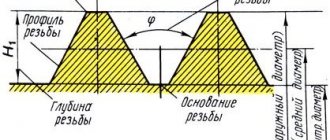
- DepressionThe surface at the base connecting two adjacent sides of the profile
- Profile flankThe surface of the thread connecting the top and bottom of the profile
- ApexThe surface connecting the two sides of the profile at the outer diameter
P = thread pitch in mm or threads per inch
The distance between two corresponding points of adjacent threads, measured parallel to the axis of the thread.
β = thread profile angle
The angle between the sides of a profile, measured in the axial plane.
φ = helix angle
The angle formed by the tangent to the helical line of the thread at points lying on the mean diameter and the plane perpendicular to the axis of the thread.
Diameter parameters
d = external diameter of male thread
D = outer diameter of internal thread
d1 = internal diameter of external thread
D1 = internal diameter of female thread
d2 = average diameter of external thread
D2 = average internal thread diameter
The effective diameter of a screw thread is approximately midway between the outer and inner diameters.
Thread angle
The lead angle of the thread (φ) depends on the diameter and pitch of the thread. This parameter can be represented as the development of a right triangle. The helix angle of the thread is calculated using the formula below.
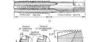
Thread cutting on a lathe
Thread cutting with taps and dies is considered a low-progressive process, since it is carried out at low cutting conditions and requires time to screw together the tools (this damages the machined surface).
Therefore, thread cutting on lathes is often performed with thread cutters.
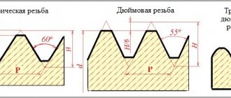
The profile of the cutting part of the thread cutter must correspond to the profile of the thread being processed. Therefore, when cutting metric threads it should be 60°, and when cutting pipe and inch threads it should be 55°. The rake angle for finishing thread cutting is zero. There are thread cutters for cutting external and internal threads. In Fig. 132, a shows the cutting of external threads, and in Fig. 132, b - internal.
Thread cutting on lathes can be performed more efficiently by using thread dies instead of conventional cutters. In shape they are usually flat (Fig. 133, a) and round (Fig. 133, b). A comb is actually several incisors put together. It consists of cutting and calibrating parts. The cutting part has two or three teeth, between which the entire allowance is distributed. This allows the number of passes required to cut threads to be reduced compared to conventional thread cutters.
Before work, the machine is set up. The essence of the adjustment is that during one revolution of the spindle, the support with the cutter must move in the longitudinal direction a distance equal to the pitch of the thread being processed. If, according to the passport, the machine does not have the required feed, then you should change the rotation speed of the lead screw, while selecting the appropriate replacement gears. After setting up the machine and securing the workpiece and cutter, threading begins. First, the cutter is set to a small cutting depth and the resulting screw mark is checked for pitch accuracy. After this, the depth of cut is gradually increased along the limb until a full thread profile is obtained. After each working pass, the cutter is removed from the workpiece, returned to its original position using mechanical feed, and again set to a certain cutting depth.
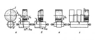
There are two cutting methods. The first of them is used for cutting threads with pitches less than 2 mm and finishing large threads. The thread cutting diagram according to the first method is shown in Fig. 134, a, from which it is clear that the cutter works evenly with both edges. During rough cutting, the chips generated by both edges of the cutter interfere with normal operation, and the machined surface may become uneven. According to the second method, the upper part of the support is installed at an angle α/2 (α is the angle of the thread profile) and is fed at this angle to the axis of the part (Fig. 134, b). With this method, the main work is performed by the left cutting edge of the cutter. Thread cutting is completed using the first method, as it provides higher accuracy.
When cutting threads, it is necessary to provide grooves for the exit of the cutter, the depth of which is slightly greater than the depth of the thread, and the width is equal to two or three thread pitches.
Universal thread turning tools
Calculation of electric current by power: formulas, online calculation, selection of machine
As the name implies, this type of cutter is used for cutting threads on parts. Threads can be external and internal, and turning tools are divided into two types, for external processing and for internal processing.
A turning tool for external threads is shown in the picture below.
Turning cutter for processing external threads.
And then a turning cutter for processing the internal thread.
Turning cutter for processing internal threads.
It is worth noting that turning cutters for processing internal diameters can cut threads in holes of sufficiently large diameter. This is explained by the geometric parameters of the cutter holder.
It’s also worth noting with regard to threaded turning tools, as with all universal ones in general, that they cannot be used immediately after bringing them from the store, they need to be sharpened correctly.
Depending on the thread profile, thread cutters are usually sharpened to 60 degrees for metric threads and 55 degrees for inch threads. Sharpening of threaded cutters is carried out using a special template.
Template for sharpening thread cutters.
Next we move on to modern types of turning thread cutters with a replaceable insert.
Power addictions.
Tangential component of the cutting force Pz, N, when cutting threads with cutters
(30)
torque, Nm, when cutting threads with taps, threading heads
(31)
where P is the thread pitch, mm;
— the number of working strokes, established from the table. 24;
D—nominal thread diameter, mm.
Coefficients SR, SM
and exponents are given in table. 27. The correction factor, taking into account the quality of the material being processed, is determined for cutters according to table. 13, for other instruments - according to table. 26.
Modern thread turning tools
GOST 16532-70. cylindrical involute gear transmissions of external gearing. geometry calculation
They are mainly used on CNC machines and have a design consisting of a holder and a replaceable insert, this insert is selected depending on the thread profile.
Thread turning tools for CNC machines
Lathe thread cutters for CNC machines are also divided into external and internal. Their purpose is exactly the same as that of universal thread turning tools.
Modern thread turning tool for external machining in the picture below
Thread turning tool for external machining
And a cutter with a replaceable insert for processing internal threads.
Thread Cutter for CNC Machines for Internal Thread Processing
The cutters presented above have the designations: 266RFG-2525-16 and 266RKF-20-16
Next, we will open the cutter data models in SolidWorks and watch a video animation of processing with these cutters.
Preparing to cut internal threads
In order for the process of cutting internal threads using a tap to not cause any particular difficulties and result in a high-quality result, it is necessary to properly prepare for this technological operation. All methods of cutting threads using a tap assume that a hole with the appropriate diameter has already been made in the workpiece. If the internal thread that needs to be cut has a standard size, then a special table with data in accordance with GOST can be used to determine the diameter of the preparation hole.
Table 1. Diameters of holes drilled for standard metric threads
If the thread that needs to be cut does not belong to the standard category, you can calculate the diameter of the hole to make it using a universal formula. First of all, it is necessary to study the marking of the tap, which must indicate the type of thread being cut, its diameter and pitch, measured in millimeters (for metric). Then, to determine the cross-sectional size of the hole that needs to be drilled for the thread, it is enough to subtract the pitch from its diameter. For example, if a tool marked M6x0.75 is used to cut a non-standard internal thread, then the diameter of the preparation hole is calculated as follows: 6 – 0.75 = 5.25 mm.
For standard threads belonging to the inch category, there is also a table that allows you to choose the right drill with which to carry out the preparatory work.
Table 2. Diameters of holes drilled for inch threads
An important question to obtain a high-quality result is not only the question of what is used to cut the thread, but also what drill to use to make the preparation hole. When choosing a drill, you need to pay attention to the parameters and quality of its sharpening, as well as to ensure that it rotates in the chuck of the equipment used without runout.
The sharpening angle of the cutting part is selected depending on the hardness of the material that needs to be drilled. The higher the hardness of the material, the greater the sharpening angle of the drill should be, but this value should not exceed 140°.
When drilling blind holes, control the drilling depth
How to cut threads correctly? First you need to select tools and consumables:
- an electric drill or drilling machine capable of operating at low speeds;
- a drill whose diameter is calculated or selected using reference tables;
- a drill or countersink, with the help of which a chamfer will be removed from the edge of the prepared hole;
- a set of taps of the appropriate size;
- manual holder for taps (drives);
- bench vice (if the product in which the thread needs to be cut needs to be fixed);
- core;
- hammer;
- machine oil or other composition, which during the processing process must be used to lubricate both the tap and the thread section being cut by it;
- rags.
Diagram of thread cutting with a tap
Quality control
To ensure that the workpiece has been processed correctly, it is necessary to use thread templates. With their help, the thread pitch is checked.
But for a comprehensive assessment, a thread gauge is used. For convenience, it is installed in a rack and adjusted according to a standard or template, then the movement of the part itself is checked.
You can also use the simplest and most commonly used method. Take a nut or bolt and scroll it over the completed part.
If scuffing is noticeable on the thread as you move, or more effort needs to be applied, then you have made an error in your work. Now you already know how to use a lathe to make various nuts, bolts or threaded connections.
It is important to remember that such parts require great care and tenderness with each pass, and even quality control. It’s better to spend more time on work than to ruin several pieces later
Thread control
The thread pitch is measured with a thread template, which is plate 2 (Fig. 4.46), on which teeth are applied with a thread pitch indicated on the template plane. A set of templates for metric or inch threads is fastened into cassette 1. Thread templates are used to determine only the thread pitch.
The correctness of the internal and external threads made on a part is comprehensively assessed using thread gauges (Fig. 4.47). Thread gauges are divided into go-through gauges, which have a full thread profile and are, as it were, a prototype of a threaded connection part, and non-go-through gauges, which control only the average diameter of the thread and have a shortened profile.
To measure the outer, middle, inner diameters and thread pitch, thread micrometers are used (Fig. 4.48). A thread micrometer has mounting holes in the spindle and heel into which sets of replaceable inserts are installed that correspond to the thread elements being measured. For ease of measurement, a threaded micrometer is fixed in a stand and then adjusted according to a template or standard.
Before testing, the parts being tested must be cleaned of chips and dirt. During the inspection process, you should handle the gauges carefully so that nicks and scratches do not appear on their working threaded surface.
Technology for using taps and dies
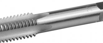
Using taps, which are a screw with several longitudinal grooves that form cutting edges and facilitate chip removal, predominantly metric threads are cut on a lathe in small-diameter holes. If machine taps are used for thread cutting, the operation is performed in one pass.
Machine taps differ from ordinary ones in that they consist of two parts - a tapping and a calibrating one. If ordinary taps are used to cut threads using a lathe, then the technology for performing this process involves the use of a set of tools. The set for cutting internal threads includes three types of taps: roughing, which does 60% of the work, semi-finishing (30%), finishing (10%). Sometimes in such a set there may be two tools: roughing, which does 75% of the work, and finishing, which accounts for 25% of the work. To distinguish a rough tap from a finishing one, just look at its cutting part: it is much longer than that of a finishing one.
Design of a tap for thread cutting
The speed of thread cutting on a lathe using taps can be quite high:
- 6–22 m per minute – for parts made of cast iron, bronze and aluminum;
- 5–12 m per minute – for steel workpieces.
Using dies, which are a ring with an internal thread and several chip grooves, external threads are made on screws, bolts and studs. The surface of the part must be pre-ground to the required diameter, which must take into account the tolerance:
- 0.14–0.28 mm – for threads with a diameter of 20–30 mm;
- 0.12–0.24 mm – for threads with a diameter of 11–18 mm;
- 0.1–0.2 mm – for threads with a diameter of 6–10 mm.
The dies with which external threads are cut are secured in a special chuck (die holder) located in the tailstock quill of the lathe.
Threading dies
Using dies, threads are cut at the following speeds (their setting also takes into account minimal tool wear during operation):
- 10–15 m per minute – on products made of brass;
- 2–3 m per minute – on cast iron parts;
- 3–4 m per minute – on steel workpieces.
Different taps for different materials
When designing taps for different materials, the rake angle and curvature of the rake surfaces of the tap are usually changed. For difficult-to-cut materials, these parameters have negative or zero values to ensure cutting edge strength. In addition, due to the large curvature of the front surfaces of the tap, when processing such materials, scoring may appear on the threads. When processing materials that produce continuous chips, taps with positive rake angles and a sufficiently large curvature of the rake surfaces are used, due to which the chips curl and break.
Another significant parameter of tap geometry is the clearance angle. For harder materials, high clearance taps are used to reduce friction and allow coolant to reach the cutting zone. But too much clearance reduces the ability of the tap to self-center. When machining ductile materials, too large a relief angle can lead to thread parameters outside the tolerance range.
Taps for cutting threads in blind holes differ from each other in the helix angle. For materials with higher strength, taps with a smaller helix angle are used. This ensures higher strength of the tap itself. For difficult-to-cut materials, taps with a short cutting length are also used to reduce cutting forces.
If you want to improve your threading efficiency, you need to pay attention to more than just the tool. For example, when cutting threads in gray cast iron with taps of the old design, you can process at a cutting speed of 10-15 m/min, and with taps of the new design - 75 m/min. But it must be remembered that such a cutting speed is achievable only under certain conditions. For example, in the absence of an internal coolant supply, the cutting speed will need to be reduced to 45 m/min, since when high-speed steel overheats, its durability is greatly reduced. When processing small threads, the spindle rotation speed may not be enough, and when processing large threads, the power of the equipment, and so on.
In addition to the geometry of the tap, the coating applied to the surface of the tool material is of great importance. Many coatings are used: TiN, TiCN, CrN, TiAlN. Thanks to the use of coatings, tool life increases and reserves appear to increase productivity.
Thread rolling technology
Threads are formed as a result of plastic deformations of the metal. The tool is pressed with great force into the body of the workpiece, the steel is squeezed into the depressions.
The following tools and devices are used for rolling:
- Rollers. Two or three devices can be used and have axial, radial or tangential feed.
- Thread rolling heads. Complex in design, but highly productive equipment. Limitation - the thread length cannot exceed the width of the head rollers.
- Flat dies. The easiest equipment to manufacture, the thread length is not limited. Used to create hardware with a diameter of 25 mm.
- Video segment. Quite complex devices allow you to obtain connections and high precision parameters.
- Chipless taps. They are rarely used due to insufficient parameters for the quality of the thread surface.
From the point of view of metalworking, thread rolling is considered one of the cold forging methods - the workpiece falls between the dies. Plastic deformation is directly dependent on the maximum percentage of elongation (ductility) and fluidity of the metal. Threads can only be rolled on workpieces made of alloys with an elongation coefficient ≥ 12%. Another factor that influences the ability to roll threads is hardness. The value depends on the microstructure of the material.
Carbide taps
Just as carbide tools have gradually replaced high-speed steel tools in turning, carbide taps are becoming more and more used in thread cutting.
Due to their fragility, carbide taps are difficult to withstand heavy loads, unlike taps made of high-speed steel. Despite this, they have proven themselves to be excellent when processing materials such as gray cast iron and aluminum with a high silicon content, because when processing these materials, the main wear mechanism is abrasive.
The development of fine-grained carbide alloys with increased strength has led to the development of carbide taps with high strength and wear resistance. They can also be used when processing hardened steel, plastics and heat-resistant alloys. Carbide taps are becoming especially widespread with the development of metal-cutting equipment.
Types and properties of cutters
Classification
In practice, cutters for external and internal threads with a rectangular section holder are used. Less common are disc, prismatic, sharpened along the front surface. The working profile of all corresponds to the dimensions of the screw groove. In the direction of the cut spiral, left and right ones are released.
There are solid and prefabricated instruments. The first ones are mainly made of high-speed steel, small section or disk. The bulk is equipped with cutting plates secured by soldering with refractory solder or mechanically, allowing replacement when worn.
Threaded cutters: external (Fig. 1), internal (Fig. 2)
Cutting depth per pass
Recommendations for plunge depth can be found in the catalog or ToolGuide. These values are recommended as initial ones, and it is necessary to select the optimal number of passes for each specific thread turning operation.
- Avoid plunging depths less than 0.05 mm
- For inserts with cubic boron nitride inserts, the penetration depth should not exceed 0.10 mm
- For multi-flute inserts, the infeed depth recommendations must be followed exactly.
Reducing infeed depth (constant chip area)
Reducing the penetration depth per pass is the most popular way to improve machining results and is the first choice in all thread turning operations.
- The first pass should be the deepest and the last should be about 0.07 mm
- Gives uniform load on the insert and a more “balanced” chip cross-sectional area
Constant plunge depth per pass
With a constant plunge depth, each pass (except the last) will be made with the same plunge depth, regardless of the number of passes. This option is less productive.
- Increases the required number of passes
- Higher plate load
- Can provide more optimal chip control
- Not recommended for use when processing threads with a pitch of more than 1.5 mm or 16 threads per inch
Thread turning cycles on CNC machines
Standard CNC lathes have specialized thread turning cycles where the pitch, thread depth and number of passes can be set in a variety of ways, including programming the first and last passes.
For the last pass, it is strongly recommended not to use a sweep pass (where the depth of cut of the last pass is equal to the depth of cut of the previous one). It is best to use the recommended plunge cycles to ensure high thread quality and insert life.