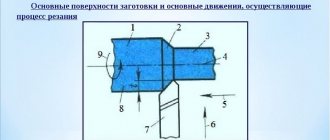
The technological process provides for the following options for grinding the outer cylindrical surfaces of parts in the centers:
- longitudinal working stroke;
- plunging (including deep and rough grinding);
- using combined grinding methods (Fig. 1).
Rice. 1. Schemes of circular external grinding: a – grinding with longitudinal working strokes: 1 – grinding wheel; 2 – workpiece to be ground; b – deep grinding; c – plunge grinding; d – combined grinding; Spr – longitudinal feed; Sp – cross feed; t – processing depth
Longitudinal grinding
used for significant workpiece lengths. In this case, the cutting depth in one pass should not exceed 0.05 mm (for roughing).
For grinding with a longitudinal working stroke, a special device is used (Fig. 1, a), the purpose of which is to transmit the rotational movement of the spindle to the workpiece. The device consists of a V-belt drive pulley and a driving disk attached to it by means of fasteners. A clamp connected to the disk with a finger rigidly holds the workpiece shank and transmits to it the rotational movement of the spindle.
For precise fastening in the centers, shallow center conical holes are drilled at the ends of the workpiece, matching in size with the cones of the centers.
The workpiece rotating around its axis, fixed at the centers, together with the machine table, carries out translational motion at a certain speed vSnp in the axial direction. Grinding the surface of rotation of a part to a given depth occurs when a rotating grinding wheel is fed in a direction perpendicular to the direction of movement of the machine table. The required layer thickness can be cut in one or more passes.
If it is necessary to remove an allowance of up to 0.4 mm in one pass, depth grinding is used (Fig. 1, b) using a conical grinding wheel. It should be noted that this type of processing can be used for cases where the part has a short length and sufficient rigidity. The main part of the cut layer is removed by the conical part of the circle; the cylindrical part of the circle ensures sufficient cleanliness of the surface.
In cases where special surface cleanliness is not required or further finishing is envisaged, rough grinding is used. The cut thickness can reach 5 mm. This type of grinding is carried out at reduced workpiece feed rates - up to 300 mm/min and is used to remove surface layers from cast, forged, stamped parts or protrusions after welding.
Plunge grinding
(Fig. 1, c) is used if it is necessary to first clean the surface of the workpiece from scale or welding seams. To do this, rough rough grinding is carried out by plunging, the grinding tool is fed in a direction perpendicular to the axis of the workpiece, reaching a given cutting depth in one or several touches. This method is ideal for processing short parts whose length is less than the width of the grinding tool.
To obtain the best results for the cleanliness and accuracy of the processed cylindrical surface, an oscillatory (oscillating) movement of the circle is used alternately up to 3 cm in both directions in the axial direction.
The plunge grinding process, in order to neutralize thermal phenomena arising from increased cutting intensity, must be carried out using intensive cooling. Additional loads also affect the geometric parameters of the tool, so it is necessary to provide for periodic dressing of the tool. A significant acceleration of the processing process using the plunge-cut grinding method can be achieved if several grinding wheels are installed on the shaft at once, thus ensuring processing along the entire length or most of the workpiece.
Plunge grinding ensures continuity and minimum feed speed, which facilitates the gradual removal of allowances and ensures the required cleanliness of the machined surface. In addition, it is convenient to process shaped parts of workpieces using wheels with a profile corresponding to the given profile of the part.
Combined method
(Fig. 1, d) grinding successfully combines the advantages of the two previous methods and is used for processing parts of considerable length.
First, a plunge grinding operation is performed with cutting off the allowance 20-80 microns less than the specified one. In this case, the wheel, moving along the workpiece, performs sequential, section-by-section, removal of the surface layer, the width of which is equal to the width of the circle.
To ensure that the treated surfaces do not differ too much from each other in height, at each subsequent stage the tool is installed at the height level of the previous processed surface. This is followed by the second stage - at an increased speed, the longitudinal finishing alignment of surface defects that arose during plunge grinding is performed.
Features of processing in centers
To perform grinding operations, the workpiece is most often positioned using the center of the machine. The configuration of the center holes can be:
- conical;
- arcuate;
- spherical.
Rice. 2. Center holes: a – with a safety groove; b – with a curvilinear generatrix; c – with a spherical center surface
Each configuration contains a special recess (Fig. 2, a), which makes it possible to ignore the inaccuracies of the conical center connections, better retain the lubricant, contributing to a significant increase in the quality and accuracy of the specified grinding conditions. If the diameter of the center holes on the part exceeds 15 millimeters, flat (fungal) centers are used. After heat treatment, the cleanliness of the center holes must be checked for contamination, and if necessary, cleaned of scale or other small particles by lapping or grinding.
The base for installing the workpiece can be an axial hole. In this case, it is convenient to use mandrels (Fig. 3): center mandrels (Fig. 3, a, c, e), installed in the centers, and cantilever mandrels (Fig. 3 d and e). There are rigid (Fig. 3, a, e and f) and expandable (Fig. 3, b, c and d) mandrels, depending on the method of fastening the parts.
Rice. 3. Mandrels: a – rigid with press fit; b and c – expansion; 1 and 5 – nuts; 2 – collet; 3 – cone; 4 – workpiece; 6 – pin; d – expanding with a sliding fit and secured with a nut: 1 – mandrel; 2 – balls; 3 – separator; 4 – bushing; 5 – screw; d and e – rigid for one and several workpieces
- On a rigid mandrel, a part with a precise hole (tolerance 15-30 microns) can be attached due to: a) the small taper of the mandrel (for a length of 100 mm - 10-15 microns);
b) due to press fit (Fig. 3, a). - On an expanding mandrel (Fig. 3, b, c, d), which is advisable to use when the tolerance of the base hole is more than 30 microns. A hydraulic or hydroplastic clamp can be installed on the expanding mandrels, which can eliminate problems associated with inaccurate execution of the workpiece hole. A mandrel with a hydroplastic clamp ensures more precise centering of the workpiece. The design of such mandrels involves thin-walled cylinders, inside of which there is a liquid or plastic under pressure. When a part is placed on a mandrel, the thin-walled cylinder is deformed, creating a tight fit of the mandrel to the hole of the workpiece.
- You can base one (Fig. 3, e, c) or several workpieces (Fig. 3, f) on a mandrel with a sliding surface, securing them at the end with a nut. Sliding fit of the part is ensured by a gap (10-20 microns).
Detailed description of the grinding process
Cylindrical grinding involves several step-by-step steps.
Basic grinding methods
Grinding with longitudinal strokes
The processed blank, after being securely fastened by rotation, moves along its own axis at a specific speed V (millimeters per minute). At the end of double or all working strokes, the wheel being processed moves in the direction that is located at right angles to the axis of the workpiece to a predetermined grinding depth. Most often, this technique is used to process various blanks that have a cylindrical surface shape. The depth is selected within values that do not exceed five hundredths of a millimeter per stroke. Finishing is performed at lower values.
Deep
Grinding with a wheel that is fed longitudinally. The method is relevant for hard materials with allowance removal of up to four tenths of a mm in just one pass. The main work is performed by the conical element of the circle, and the cylindrical element performs the cleaning. In general, this method can be considered from the point of view of rough grinding. Depths are more than five mm, longitudinal feed rates vary from one hundred to three hundred (mm per minute) per single stroke. The stripping method refers to the removal from the plane of the blank of an unusable layer that has a number of defects after the process of casting, rolling, and so on.
Mortise
Used for roughing and finishing methods. The latter method, unlike the first, is necessary to give the desired geometric shapes, as well as the level of roughness of the blank plane itself. Grinding is carried out with a single circle of large width; its height is one...one and a half mm greater than the length of the grinding area. The blank is without movement. The circle is fed periodically or continuously. To achieve a small deviation in shape and roughness, the circle is given an oscillatory movement (up to three mm) in two directions (l/r)
Advantages:
- Continuous feed of the circle.
- Working with shaped materials using a profiled wheel.
- Installing up to three circles on the spindle simultaneously, thereby processing several areas at once.
Minuses:
- Generating excessive heat.
- Requires more frequent cooling with colossal productivity.
- Frequent straightening of the circle, as the given geometric shape is quickly lost.
Combined method
Combination of machining with longitudinal strokes and insertion. Let's use this method for long blank materials. At the initial stage, one part is ground with a transverse feed, then the adjacent section. In this case, the edges of two and subsequent sections overlap each other by five...ten mm, thereby resulting in a stepped geometry. For this reason, only part of the allowance is removed, and the rest (two...eight hundredths of mm) is eliminated by two or three longitudinal movements, which have a higher speed.
Precision processing of long lengths
In cases of grinding long parts, it is difficult to maintain the specified accuracy. Due to the influence of cutting forces, deformations of the rod occur, violating the established parameters, causing vibrations and oscillations. All these phenomena disrupt the overall rigidity in the LED system. This can be avoided by installing one or more supporting structures - steady rests - along the length of the workpiece. The structure of the most commonly used steady rests contains one or two blocks (Fig. 4) that support the workpiece, one of which reduces the radial (horizontal) load, the other - the vertical (tangential) load. The rod installed in the mandrel or in the centers is supported in the desired position by means of vertical and horizontal blocks, adjusted by screws installed in the steady rest body.
Rice. 4. Steady rest with two blocks: 1- screw; 2 and 5 – rings; 3 – steady rest body; 4 – screw; 6 – quill; 7 – block; 8 – workpiece; 9 – polished wheel; 10 – vertical block; 11 — lever
During the grinding process, the position of the supporting blocks should be checked and adjusted in accordance with the diameter of the rod decreasing during processing. The adjustment is made with both screws, with preference given to adjusting the block 7 with screw 4 in the horizontal direction - in this direction the grinding wheel exerts the greatest pressure on the workpiece.
Before performing the grinding operation, the machine is set up according to the standard, installing restrictive rings that prevent the movement of the adjusting screws.
Features of cylindrical grinding machines
Control is carried out manually using mechanical and hydraulic drives. Also, many modern installations are equipped with a numerical control (CNC) panel, which allows automation of most production processes. This not only simplifies the worker’s task, but also has a beneficial effect on the quality of processing.
To be allowed to install (both with and without a CNC panel), the worker must undergo appropriate training. He must also undergo training regarding workplace safety rules. During operation, a person must be careful not to damage the part and harm his health. Depending on the design, the following types of installations are distinguished:
- Simple machine. In such installations, you can only change the angle of the table on which the main part is fixed, and the grinding disk has a fixed position. This makes it possible to process cone-shaped parts with a small apex angle. The fixed location of the disk impairs the versatility of the system, but significantly reduces its cost. Therefore, in the case of small industries (auto repair shops, home construction), purchasing a simple machine may be a justified decision.
- Universal cylindrical grinding machine. On such systems, both the table and the processing disk can be rotated. This allows you to grind all types of parts (flat, conical, end, variable diameter), as well as individual holes inside workpieces. A universal cylindrical grinding machine is usually equipped with a CNC, which can significantly increase the quality of processing. Such installations are more expensive than simple systems, and they are usually used in industry (mechanical engineering, repair of ships or aircraft, weapons production).
Methods for dressing grinding wheels
During operation, grinding wheels are subject to wear, which necessitates their periodic dressing. To do this, use a diamond pencil or a special mandrel, which are installed in the tailstock quill. A micrometric pencil feed device allows you to edit the circle with maximum accuracy. It is also possible to edit using automatic edit of the wheel in one or two passes along the copier (stepped or smooth), using a special device located on the body of the grinding headstock.
Cylindrical grinding
You can order cylindrical grinding services by phone,
| Sales Department Manager Mezentsev Yuri Vladimirovich |
Cylindrical grinding machines are intended for grinding operations, which are carried out using these machines on cylindrical and axial end surfaces. The accuracy class of the work performed is IT6 and IT5. The workpiece fixed on the machine in special centers or chucks is driven into a rotational motion directed towards the grinding wheel. Thanks to the table, the product can also move in a reciprocating direction. After each table stroke, or its double movement, the grinding table moves in the transverse direction to the depth of cut. The movement of the working table in the longitudinal direction occurs using a flywheel or due to a hydraulic system. In the latter case, the movement occurs steplessly.
The feed of the grinding head, the so-called working feed, occurs through manual control (flywheel), or using an automatic hydraulic system. The hydraulic drive is also responsible for the rapid approach and retraction of the grinding headstock. Using the flywheel, the operator has the opportunity to carry out both roughing and finishing cylindrical grinding with longitudinal and transverse movement.
The scope of use of cylindrical grinding machines is small-scale and mass production, tool workshops, service enterprises. As standard, a cylindrical grinding machine consists of the following main units and parts:
- calipers;
- three-jaw chuck;
- faceplates;
- straightening devices;
- device for internal grinding work;
- balancing device;
- control center;
- coolant tank.
Modifications of cylindrical grinding machines
There are three main types of cylindrical grinding machines: center, centerless and internal grinding machines. Let's look at the features of grinding using the example of center cylindrical grinding machines.
This type of machine is used to process the outer surfaces of products that have the shape of a body of rotation with straight generatrices, as well as cylindrical and conical surfaces. In this case, the technological bases are cylindrical outer surfaces or central holes. Depending on the direction of grinding movement, several grinding methods are distinguished.
The plunge-cut grinding method ensures processing of the workpiece while it performs a rotational movement. In this case, the feed movement occurs in a direction that is perpendicular to the axis of the workpiece.
In oscillating grinding, the workpiece or grinding wheel undergoes not only rotational motion, but also reciprocating motion. This method allows you to process surfaces whose length significantly exceeds the height of the grinding wheel. At the completion of each pass, the wheel moves to a predetermined working depth.
If you combine oscillating and plunge machining, you get a new grinding method called shoulder grinding. In this case, by sequential cutting into the wheel, the shoulders that overlap each other are ground, and the remaining allowance is removed using oscillating grinding.
When deep-feed grinding, the feed can be either transverse or longitudinal. If the method with longitudinal feed is used, then the allowance is removed from the workpiece at a time, that is, in one cycle of rotation of the circle. The latter is adjusted either to a cone or a step. During one revolution of the workpiece during transverse feeding, the entire allowance is also removed. the difference is that in the first case the circle rotates, in the second the product rotates.
The most difficult type of processing is external cylindrical grinding. In this case, both the circle and the workpiece rotate. In addition, there is a transverse movement of the workpiece or circle, as well as longitudinal feed, that is, reciprocating movement of the product or circle along its own axis. Surface roughness after processing is measured in hundredths of a micrometer (usually about 0.04 microns).


