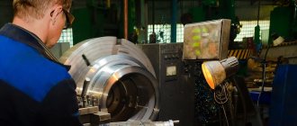
Metal grinding
The processing of metal and various alloys using an abrasive material is usually called grinding. This technology allows you to change the roughness and other parameters of the outer or inner cylindrical, as well as flat surface. Metal grinding can be carried out using various special equipment. When considering the features of such mechanical processing, you need to pay attention to the following points:
- The grinding process is the final stage of processing, which is carried out to obtain a certain roughness.
- This technology is not used to change sizes over a large range.
- Using modern equipment, the surface can be brought to the required roughness after heat treatment of the metal.
When carrying out the operation in question, a fairly large number of features are taken into account:
- Wheel speed is a parameter that depends on the outer diameter of the abrasive and the capabilities of the machine.
- Speed of movement of the part.
- Depth of cut.
- Possibility of cross feeding.
It is worth noting that today such technology is gradually being replaced by fine turning of metal at high speeds and minimal feed.
Main types of grinding
Grinding of parts can take place using a variety of technologies. The most widespread are the following:
- Circular grinding of metal.
- Changes in the roughness of internal surfaces.
- Gear grinding.
- Centerless technology.
- Sanding flat surfaces.
In addition, classification can be carried out according to the type of material used during processing. To automate the process and reduce labor costs, specialized machines are used. There are also models with a built-in CNC unit, which automates the process and ensures high quality of the resulting surface.
Cylindrical external grinding
Metal grinding when using this technology involves the use of special equipment. Among the features of cylindrical grinding, we note the following points:
- An abrasive wheel is used as a consumable. It rotates around its axis.
- Simultaneously with the circle, the workpiece rotates in the opposite direction. Due to this, the efficiency of the operation is significantly increased.
- Longitudinal and transverse feeds can be carried out, due to which the depth of penetration of the tool changes and processing is ensured along the entire length.
Principle of cylindrical grinding
Cylindrical external grinding
This technology is often used for grinding cylindrical workpieces. This is due to the fact that when the grinding wheel comes into contact with a cylindrical workpiece, the entire surface is processed at the moment of rotation.
Technology of processing workpieces on cylindrical grinding machines.
External round finishing of parts such as rotating bodies on centering machines can be carried out using longitudinal working strokes, plunge grinding or a combination.
When grinding using longitudinal working strokes, the part, rotating in fixed centers, performs longitudinal movement along its axis at a certain speed V, which is measured in mm/min. At the end of a double or each stroke, the abrasive wheel moves in a direction perpendicular to the axis of the workpiece to grind to the required depth.
This method is very often used for grinding objects with a cylindrical surface of considerable length. A grinding depth of no more than five hundredths per stroke of the machine table should be used. But it should be remembered that with fine grinding the size of the cut layer is much smaller.
Deep grinding as one of the types of grinding using longitudinal feed of the grinding wheel is used for processing hard short objects with material cutting up to 0.4 mm in one working stroke of the abrasive wheel. The allowance is removed using the conical part of the grinding wheel, and its cylindrical part cleans exclusively the working surface of the part.
Creep-feed grinding can be considered one of the varieties of plunge-cut grinding. Processing occurs at great depths of more than 5 mm, at low speeds of longitudinal movement from 100 to 300 mm per minute, in this way in one table stroke. Grinding refers to mechanical processing to remove defective layers of material from a part after welding, stamping, rolling, forging or casting.
Flat grinding is used for rough and finishing grinding of cylindrical workpieces. After finishing grinding, as opposed to non-finish grinding, it is necessary to maximize the desired shape and roughness parameters of the part being ground. Grinding takes place over one wide circle, the height of which is 1 or 1.5 mm greater than the length of the surface being sanded. The workpiece is rigidly fixed and longitudinal feeding is impossible; The lateral movement of the grinding wheel to the initially set grinding depth occurs without interruption or with a certain frequency. To obtain a surface with less shape deviation and roughness, the grinding wheel provides an additional axial oscillatory movement to the left and right of up to 3 mm.
This method of processing the workpiece has the following advantages over the grinding method using longitudinal movements:
o the movement of the feed wheel occurs continuously;
o You can grind workpieces using a profiled grinding wheel;
o 2 or 3 grinds. wheels can be applied on the machine spindle and simultaneously grind several parts of the workpiece.
Disadvantages of the embedding method:
o a large amount of heat is generated due to high efficiency;
o the wheel and workpiece heat up more than during normal grinding, so grinding should be carried out with intensive cooling;
o It is often necessary to correct a circle due to the rapid distortion of its geometric shape.
In the case of combined grinding, grinding is combined with longitudinal movements and immersion. This method is used when sanding long objects. First, one section of the shaft is ground with a lateral movement of the wheel feed, then with an adjacent section, etc. The edges of the segments overlap by 5 or 10 mm during grinding, but the surface is graded. Therefore, the partial constraint is removed at each location. The remaining layer of about 0.05 mm is removed with two or three longitudinal strokes at increased speed.
Devices for installing and securing wheels on cylindrical grinding machines are similar to the devices used for wheels of the same diameters on surface grinding machines.
The center at the back and the center at the front do not rotate. When processing a cylindrical surface of a workpiece, the axis of the wheel is parallel to the axis of the machine centers.
The center is installed in the spindle head of the machine. Rotation from the electric motor through the V-belt drive pulley is transmitted to the workpiece using a drive disk, pin and clamp. Special central holes are made at the ends of the workpiece (Fig.). The conical surfaces of these holes, when installing the workpiece, are connected to the conical surfaces in the center of the headstock and tailstock of the machine.
In some cases, the center holes are used with a protective groove or with a curved arch that forms a support cone. The advantages of central or spherical holes are their insensitivity to angular errors, better lubricant retention, reduced installation errors and greater machining accuracy. Workpieces with holes or undercuts on the front surface with a diameter of more than 15 mm are processed on an opaque substrate.
If the workpiece is subjected to heat treatment before grinding, the center holes must be cleaned of scale and dirt from grinding or grinding before installing the workpiece on the machine.
If there is a hole in the part, it may be based on spindle machining. According to the installation method, the pins are divided into center and hand; depending on the installation method - rigid and expandable.
Workpieces with precise base holes with a tolerance of 0.015 ... 0.03 mm or less are mounted on rigid mandrels with a small taper of 0.01 ... 0.015 mm per 100 mm or a press fit. When using less precise base holes, expandable mandrels are used. If the workpiece simultaneously rests on the surface and the hole, then mandrels with a sliding fit are used, on which one workpiece is installed or several workpieces are secured with a nut.
Spreaders also include mandrels with hydraulic or hydroplastic clamping. These mandrels can more easily accommodate inaccuracies in hole shapes, so the workpiece will be more accurately centered. The workpieces are mounted on such mandrels, deforming a thin-walled cylinder under uniform pressure from the inside. Liquid or plastic is used to create pressure.
Various straps, clamps, and chucks are used to transfer torque from the front of the machine to the workpieces.
When grinding objects whose length is 5-10 times greater than the diameter, the cutting force causes the object to deflect due to insufficient rigidity. At the same time, the grinding accuracy decreases, and oscillations and vibrations may occur in the LED technology system. In these cases, one or several permanent telescopes are used - additional supports for the workpiece.
In mass and mass production, adjustable telescopes with one or two washers are used. To produce radial (horizontal) and tangential (vertical) cutting elements. In the design, the remaining vertical position of the block mounted on the latch arm is fixed using an adjustment screw that moves in the rest of the housing. The position of the horizontal block mounted on the tip is adjusted using a screw. From the grinding workpiece around the wheel, it is necessary to adjust the position of the blocks, since the diameter of the polished surface decreases. The final position of the blocks depends on the diameter of the workpiece. When setting up a machine, the washers are set in accordance with the reference part or gauge using rings and, which limit the axial movement of the adjusting screws and. It is recommended to adjust the position of the washers using a screw, since the horizontal movement of the workpiece has the greatest impact on the processing accuracy.
.
Abrasive discs. The diamond pencil in the handle has a micrometric feed, which is performed by manual rotation of the handle. A diamond-free straightening pin can also be installed on copings. An automatic wheel dressing device is installed on the grinding blade body. The right device allows modification in one or two steps on a single or detailed copy. The correct device is activated by a control relay that counts the number of parts polished, or the operator presses a button for this purpose.
Measurement and measuring methods for circular grinding. In small-scale production, micrometers are widely used to measure the diameter of the grinding surface. Rigid and signal brackets are preferred in mass production. The fixed support has rigid or adjustable dimensions of the measuring jaws. The information in brackets is indicated: “pass” or “fail.” The indicator bracket shows the actual dimensions compared to the standard and allows the process to be monitored according to the remote limit.
Automatic disc grinders use automatic measuring tools and slave controllers.
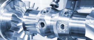
Gear grinding
Gears are part of a wide variety of mechanisms. The complexity of the shape of the working part determines that special grinding equipment has to be used. Among the features of this technology, we note the following points:
- The profile of the ring gear is processed.
- The circle changes to the size of the tooth involute.
- Special machines are suitable for working with gears.
Gear grinding
Often the tooth surface is hardened, which makes the machining process significantly more complicated.
Centerless grinding
This technology is characterized by the fact that the workpiece is not fixed in the centers. In this case, grinding of metal parts takes place by applying rotation to only two grinding wheels, between which the workpiece is placed. In the central part there is a knife made of stainless steel. It eliminates the possibility that the product will fail due to displacement or become slightly jammed.
The use of such equipment can significantly speed up the grinding process. This is due to the fact that two abrasive wheels are used at once. There are simply a huge number of machines on sale that operate on the principle of centerless grinding.
Centerless grinding
Wear, durability and wheel dressing
During the grinding process, the cutting properties of the wheel change. Abrasive grains become dull, partially split, and crumble; the pores between the grains become clogged with grinding waste (the wheel becomes “greasy”); the surface of the circle loses its original shape. As a result, the cutting force and temperature increase; processing accuracy decreases and the likelihood of burns increases. However, when the dull grains are broken out, new, sharpened grains are exposed on the surface of the wheel, i.e., the wheel partially sharpens itself. In this sense, the role of the binder (the substance that fixes the grains) and the “hardness” of the circle is very important. If the grain is weakly secured, they break out faster, the wheel sharpens itself better, but the working surface of the wheel quickly loses its shape, which is convenient for rough grinding. If the grains are excessively fixed, the wheel quickly loses its cutting properties, but the working surface is well preserved, which is convenient for fine grinding.
To restore the geometry of the wheel and its cutting properties, the wheel is edited. A diamond or abrasive tool is used to remove part of the working surface of the circle. The thickness of the removed layer usually does not exceed 0.01–0.03 mm.
The geometric durability of a grinding wheel is the time (number of processed workpieces) of continuous operation, after which editing is necessary in order to restore the geometric parameters of the working surface. Geometric resistance is usually prescribed for finishing grinding, for grinding shaped or conical surfaces. The physical durability of a grinding wheel is the time (number of processed workpieces) of continuous work, after which dressing is necessary in order to restore the cutting properties of the working surface. Physical resistance is usually specified for rough grinding.
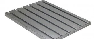
Sanding flat surfaces
Flat body blanks made of various metals are often processed. The operation to change the surface roughness is characterized by the following features:
- The workpiece is placed on a special table, which ensures reliable fastening. Fixation can be mechanical or magnetic.
- The main rotation is transmitted to the abrasive wheel, reciprocating the workpiece or tool.
Sanding flat surfaces
By selecting a wheel with the most suitable profile, it is possible to process the most complex shapes. During operation, coolant can be supplied to the contact area between the tool and the workpiece.
Features of the cutting process during grinding
An abrasive tool, unlike a blade tool, has many cutting microblades arranged randomly. A single grain of a grinding wheel can be located at a certain distance from the machined surface, slide along the machined surface (sliding grains), penetrate into the machined surface to a small depth and deform the workpiece material only plastically (deforming grains), penetrate into the machined surface to a depth sufficient for removal chips (cutting grains). Compared to blade processing, grinding is characterized by increased cutting resistance, since sliding grains create additional friction, deforming grains create additional elastic and plastic deformation, and the cutting angles of the cutting teeth are not optimal. In addition, the cutting force on a single grain is greater, but since microchips are removed, the total cutting force is small. Due to additional friction and deformation, the temperature in the cutting zone is much higher than during blade processing, so structural transformations of the metal in the cutting zone (burning) are possible. The shavings burn in the air in the form of a sheaf of sparks, which requires additional fire and sanitary safety measures.
Processing parts before grinding
As previously noted, sanding is the finishing step. Before it is carried out:
- Rough turning of metal. Due to this operation, the workpieces are given the required shape and dimensions, taking into account the allowance.
- Finish turning is carried out to give the required dimensions.
- Milling is another technological operation that involves mechanical removal of metal. Most often, housing parts and gears are milled.
- Heat treatment. In order to significantly increase the surface hardness and strength of the product, hardening is carried out. The fragility of the structure can be reduced by tempering and annealing. In some cases, thermochemical treatment is carried out, which involves introducing certain chemicals into the surface layer.
Processing parts before grinding
When developing processing modes, allowance for all technological operations is taken into account.
Characteristics and marking of abrasive tools
In most cases, when grinding metal, an abrasive tool is used. It is represented by a combination of a large number of grains, which are interconnected by a special lubricant. The circle is characterized by the following properties:
- Form. The working part may vary depending on what type of surface will be processed.
- Dimensions. The abrasive wheel is also selected by size depending on the dimensions of the surface being treated.
- Type of material used in manufacturing. The crumb can be made from crumbs of different hardness. Diamond chips are characterized by greater resistance to abrasion.
- Grain size. For fine grinding of metal, a wheel with the smallest grain size is selected. However, as the grit size decreases, the required time to complete processing increases.
- Surface hardness. This parameter is one of the main ones, indicated during labeling.
- Mounting hole size. It is taken into account when selecting a wheel for the characteristics of the machine.
The production of abrasive materials is carried out in accordance with established standards and technical conditions.
Circle markings are used to indicate the type of material used in manufacturing. Electrocorundum is artificial corundum based on aluminum oxide. There are several varieties of circles available for sale:
- Normal 14A and 15A, 16A.
- White 22A, 23A and 24A.
- Chrome 32A and 33A.
- Spherocorundum ES.
Silicon carbide can also be used. There are two types of stamps on sale: black and green. Boron carbide is marked with the letters KB. Recently, the most popular options are made from synthetic diamond; they are marked ACP and ASO, ARV and ARC.
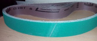
Abrasive materials
Basic grinding schemes.
⇐ PreviousPage 11 of 26Next ⇒
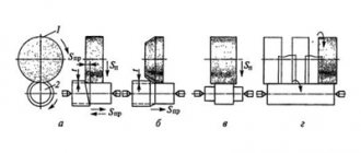
The parts of modern machines are a combination of flat and circular cylindrical, conical external and internal surfaces. Other surfaces are less common. In accordance with the shapes of machine parts, the most common grinding schemes are shown in Fig. 22.
For all technological methods of grinding, the main cutting movement VK (in m/s) is the rotation of the wheel.
In surface grinding, reciprocating motion
Fig.22
of the workpiece is the longitudinal feed Spr (in m/min) Fig. 22 (a). To process the surface over the entire width b, the workpiece or wheel must move with a transverse feed SP (in mm/double stroke). This movement occurs intermittently (periodically) at the extreme positions of the workpiece at the end of the longitudinal stroke. The feed Sв (in mm) to the cutting depth is also periodically carried out, which is also carried out in the extreme positions of the workpiece, but at the end of the transverse stroke.
During cylindrical grinding (Fig. 22 (b), longitudinal feed occurs due to the reciprocating movement of the workpiece. The feed Spr (in mm/rev, zag.) corresponds to the axial movement of the workpiece per revolution. The rotation of the workpiece is a circular feed Scr (in m/min):
where nzag – workpiece rotation speed, rpm; Dzag – workpiece diameter in mm.
Feed Sp [in mm/d. stroke (mm/stroke)] to the cutting depth for the given processing scheme is carried out at the extreme positions of the workpiece. The movements carried out during internal grinding are shown in Fig. 22 (c).
Modern grinding machines provide all the movements indicated in the diagrams and allow cutting and feed speeds to be changed within the required limits.
Surface treatment during grinding is carried out with a tool made of abrasive material.
Abrasive tools are distinguished by geometric shape and size, type and grade of abrasive material, grain size or size of abrasive grains, binder or type of binder, hardness, structure or structure of the wheel. In most cases, the shape of the abrasive tool is a circle of a certain thickness. The cross-sectional shape of grinding wheels and their dimensions are regulated by GOST 2424–75.
Abrasive tool grains are man-made or natural minerals and crystals. Natural minerals used include diamond, quartz, corundum, emery, flint, and garnet. Artificial minerals include normal electrocorundum (E), white electrocorundum (EB), monocorundum (M), green silicon carbide (SC) and black (SC), etc.
Diamond wheels are successfully used for grinding workpieces made of hard alloys and high-hard materials. The diamond wheel consists of a body and a diamond-bearing layer. The housing is made of aluminum, plastic or steel. The thickness of the diamond-bearing layer for most wheels is 1.5–3.0 mm.
Grinding of workpieces, depending on the surface being processed, is carried out on cylindrical grinding, internal grinding, surface grinding and on specialized machines.
The designs of cylindrical grinding machines and their layout are subject to the basic grinding schemes. The machines provide all the movements and kinematic relationships necessary for processing.
The cylindrical grinding machine Fig. 23 consists of the following main components: bed 1, table 2, headstock 3 with gearbox, grinding headstock 4, tailstock 5 and table drive 6. These machines are divided into simple, universal and mortise.
Universal machines have a rotating headstock and grinding headstock. Each headstock can be rotated at a certain angle around a vertical axis and secured for subsequent work. Simple machines are equipped with fixed headstocks.
Rice. 23
Plunge-in machines do not have a longitudinal table feed, and grinding is carried out along the entire length of the workpiece with a wide abrasive wheel with a transverse feed.
The grinding wheel rotates using a V-belt drive. After the circle wears out and its diameter decreases, another pair of pulleys is used.
Internal grinders have a similar layout to cylindrical grinders, however they do not have a tailstock. The tool is located on the cantilever spindle of the grinding head, which is mounted on a table that performs a longitudinal reciprocating movement.
Internal grinding is used to obtain high precision holes on workpieces, usually after heat treatment. It is possible to grind through, non-through (blind), conical and shaped holes. The diameter of the grinding wheel is 0.7–0.9 times the diameter of the hole being ground. The circle is given a high rotation speed per minute: the smaller the diameter of the circle, the higher it is. Grinding productivity is reduced due to the need to work with low feeds and cutting depths of a cantilever wheel and its frequent dressing.
A general view of the surface grinding machine is shown in Fig. 24. A surface grinding machine with a rectangular table consists of a frame 4, a table 3, a stand 2, a grinding head 1 and a table drive 5.
Flat surfaces are ground with the periphery of a wheel. The feed movements are carried out by the machine drive or manually. The longitudinal movement of the Spr table is most often ensured using a hydraulic device - a piston, cylinders and controls.
Fig.24
On specialized grinding machines, the surfaces of workpieces of a very specific type are processed.
On thread grinding machines, the grinding wheel is threaded to the shape of the thread root, which, as a rule, is pre-cut on other machines. The ground thread has high precision and low surface roughness. To increase grinding productivity, the profile of the abrasive tool must ensure the simultaneous processing of several turns of thread (multi-thread wheel).
Non-circular cylindrical surfaces (cams) are ground on specialized semi-automatic machines. In most cases, the profile of the cams is outlined by circular arcs of several radii or by circular arcs and straight lines. Such surfaces located on the shafts are ground using a pattern.
The corresponding specialized grinding machines are used for processing spline shafts, tooth profiles of gears, complex shaped surfaces of dies, molds and other parts.
Grinding is widely used in sharpening machines for processing a variety of cutting tools. When sharpening on turning-grinding machines, the cutters are placed on a rotary table or tool rest, and then manually pressed against the grinding wheel with the surface being processed. Sharpening cutters on universal sharpening machines in a rotary vice allows you to obtain the most accurate geometric parameters of the cutting part of the cutter.
The use of program-controlled sharpening machines in CNC production allows, in parallel with the design of a part manufactured on CNC machining centers, to design and manufacture the entire line of metal-cutting tools for the manufacture of parts on CNC machining centers.
⇐ Previous11Next ⇒
Recommended pages:
Use the site search: