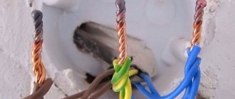
Copper wires are more practical than aluminum wires; they are often used for wiring in private homes and laid when renovating apartments. Several ways of designing cable joints are allowed: they are secured with terminals or soldering. Crimping or compression of the twist is allowed, but the most reliable connection is formed by molten copper. To weld copper wires on a line or in a distribution box, spot technology is used. It is necessary to melt the twist to a homogeneous structure so that the resistance in the circuit does not increase. This is done for fire safety.
Using an inverter
Copper wires, most common in residential buildings, are connected in several ways, but welding is considered the most reliable.
As a result of this connection, a homogeneous conductor is obtained, which ensures complete fire safety. Welding is carried out with direct or alternating current voltage from 12 to 36 V, and the welding current must be adjusted. Most welding inverters meet these requirements. They produce a special apparatus for welding copper wires, which is used by electricians. It has a power range of 1-1.5 kW and welding current adjustment in the range from 30 to 120 A.
Unlike conventional inverters, the equipment has less weight and dimensions; in addition, the ends of the welding cables are equipped with a special holder for carbon electrodes and a clamp with a large clamping surface for the conductors. If the farm already has an inverter welding machine, then you don’t need to buy a special device for welding copper wire.
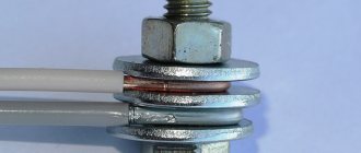
For convenience, pliers and an electrode holder are welded to the welding cables or attached through a bolted connection. Any powerful clamp can play the role of a carbon electrode holder. Its handles must first be insulated.
The pliers are attached to the ground wire. They will hold onto the twist of the copper conductors being welded, while they will perform the important function of heat removal. This is necessary to protect the insulation from exposure to high temperatures.
Procedure
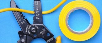
When welding wires with your own hands, the procedure will be as follows. First, you need to remove the insulation from the ends of the conductors to be welded to a distance of 8-10 cm.
When removing insulation, do not damage the wire cores. Before twisting, they must be cleaned with sandpaper and wiped with acetone to degrease.
Then the copper wires to be connected are twisted and the ends are cut with wire cutters so that the end of the twist is flat. The result should be a bunch about 5 cm long.
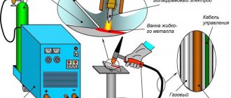
The preparatory work ends here, and the welding itself begins. The ground clamp of the turned on welding machine is attached to the twist, and a graphite or carbon electrode is brought to the end of the twisted conductors, which is held at the end of the second welding wire using a special holder.
As a result, a short circuit occurs with the formation of an electric arc. Its energy is enough to melt the ends of copper conductors in 1-2 seconds.
A molten drop of copper forms at the end of the twist; it needs to be given time to cool. After this, the twisted area is insulated with tape or heat-shrink tube (the tube must be put on in advance).
The welding joint is of high quality; its electrical characteristics do not differ from those of the entire copper wire, and will last no less than it.
Process modes and features
Due to the limited welding currents, devices for fusing electrical wires can have very small sizes. Thermite welding of wires, which is widely used among specialists and is organized using a special powder mixture, makes it possible to further simplify the welding procedure. In this case, it is possible to significantly reduce the dimensions of the portable equipment used.
When carrying out ordinary electrical operations (including welding copper and aluminum wires), special equipment is used, which uses direct current of direct polarity to form an arc. The plus of the supply circuit is connected to the electrode holder in such a device, and its minus is connected to the grounding wire, which is usually called “ground”.
When welding with certain types of copper-coated electrodes, reverse polarity is used.
The magnitude of the welding current in any case is determined by the dimensions of the electrical wire harness being installed and the cross-section of the individual cores collected in it. During the welding process, the required value of this parameter is set using a regulator located on the control panel.
Various models of small-sized welded units provide adjustment of the output voltage. Some manufacturers and even home craftsmen further improve the design of their models by installing special current limiters in them. Data on the output parameters of such devices can be found in the tables of the dependence of the operating voltage and current on the cross-section of the wires being welded and their number in the twist.
Pros and cons of welding, its varieties
The advantages of connecting wires by welding are the absence of transition resistance, which is always present in twisted or bolted connections. This is especially true when laying wiring for powerful devices. The disadvantages are the need to buy or make your own welding machine designed for twisting.
Welding work requires some skills, so the electrician who will weld the strands needs to learn at least the basics of this craft.
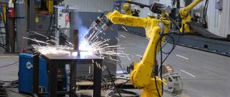
When performing electrical installation work in production, various types of welding are used: standard, arc spot, plasma, torsion, electron beam, ultrasonic, or various combinations thereof. For domestic use, electricians most often use a device for spot and arc welding, which operates on carbon or graphite electrodes.
This solution allows you to obtain good quality connections at a minimum cost of the necessary devices and components. When making a wire welding machine, most attention should be paid to the following characteristics of the device:
- The current strength that the device can produce. Ideally this is a variable value.
- The voltage produced by the device is sufficient to cause an electric arc - usually 12-32 Volts.
- What kind of current does the welder use - alternating or direct? If you have experience in such work, you can use variable, but for beginners it is strongly recommended to start with constant.
Since welding different metals requires different currents and voltages, universal welding machines can necessarily adjust these values. In addition, when joining different materials, you may need special fluxes that will protect the metal from oxidation or the penetration of gases from the air into it. Most universal-purpose welding machines are quite bulky and heavy, but for small welding jobs you can find inverter welders for a relatively low price that are ideal for welding wires.
If you are welding copper wires that are used in home wiring, there is no need to use very high current and voltage, so it is possible to use small-sized welding machines that fit into a standard tool case.
How to prepare for welding
A strong connection is formed as a result of melting of the welded elements under the influence of current. The clamping design makes the diffuse layer denser.
At the preparatory stage, perform the following actions:
- Organize a workplace. Remove all flammable materials from the operating area of the device.
- Clean the ends of the conductors to be welded. The insulation is removed at a distance of up to 70 mm. This eliminates the possibility of wire breakage during connection. When removing the braid, damage to the cores is avoided. Before twisting, they are treated with sandpaper and degreased with a solvent.
- Twist the cleaned wires, folding them parallel. The method of twisting does not matter, however, with axial joining, the welding process is easier. The ends of the wires are removed with wire cutters, forming a flat end. As a result, a beam with a length of 50 mm is formed.
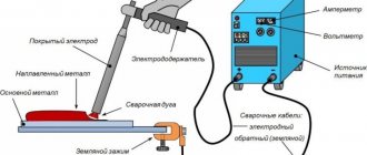
The principle of operation of arc welding - device diagram
Since welding requires a large current, the basis of any welding machine is a step-down transformer - a loss in voltage is always accompanied by a gain in current and vice versa. A standard diode bridge is used to convert alternating current into direct current, and a capacitor is used to smooth out ripples.
A noticeable disadvantage of using a direct current device is that the diodes and capacitor used are rather large and they significantly increase the weight of the welding machine, which is initially made portable.
Experts also recommend installing additional resistance at the input or output of the diode bridge, since diodes “do not like” a short circuit in its pure form.
Many craftsmen manually assemble a welding machine for welding copper wires, which produces an arc from alternating current and use them successfully. Therefore, it is impossible to say unequivocally that it is necessary to use a direct current device - everyone chooses the necessary model according to their skills. If an AC welding machine is manually assembled, then the diode bridge and capacitor are simply thrown out of the circuit.
A necessary skill that you will have to master to use an AC welding machine is to learn “by eye” to determine how long you should hold the ignited arc of the electric discharge so that the end of the twist heats up and fusions.
The most common way to make a negative contact for welding is with old pliers that hold the wires.
For the phase, take a clamp that can hold the graphite rod. The design of the clamp can be very diverse - from a screw connection to the so-called “crocodiles”, both home-made and factory-made. To connect to the welding machine itself, cables with a cross-section of about 10 mm² are used.
Despite the fact that a device assembled in an industrial environment is an order of magnitude more expensive than a homemade one, its price is not exorbitant and allows you to purchase such a welding machine even on a limited budget. The advantages of its use are obvious - it is a precisely calculated design with a current regulator, which allows you to work with different types of metals and the number of wires being welded.
Wire connections overview
Mechanical connection:
1. Twist. It is prohibited in its pure form, since there is no reliable contact to ensure the passage of current, the PUE is prohibited: clause 2.1.21. Currently, twisting is used as a preliminary operation before welding.
2. Clamps. Three types of clamps are used: spring terminals, which provide the necessary pressure while the spring stiffness is maintained; screw ones, in which there is a possibility of loosening threaded connections and, as a result, weakening of contact; clamping terminals – provide contact with mechanical eccentric clamping.
3. Pressure testing with sleeves. This type is one of the most reliable. But for it it is necessary to have a set of special sleeves of suitable diameter and crimps to ensure the necessary pressure requirements.
Permanent connections:
- Soldering. Allowed to be used when connecting thin wires with low current load. Soldering of copper cables for household and industrial purposes is not recommended in PUE Chapter 4.2, clause 4.2.46 due to the oxidative processes taking place in tin-lead solders.
2.Welding. One of the most reliable and PUE-approved types of connection in electrical circuits for power purposes.
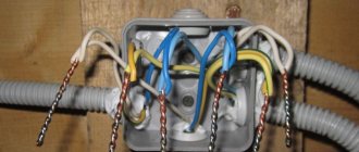
Features of wire welding
First you need to make the correct installation of the wiring - choose its optimal diameter, correctly position it in the walls of the room. To distribute lines, special boxes are installed. There it becomes possible to redirect the supply of electricity from the central wire to the auxiliary one.
Welding wires in a box has the following nuances:
- Use of inverter welding machines with power up to 1 kW. These can be factory models or homemade ones.
- Electrodes - graphite or carbon. It is not recommended to use copper-plated rods, as this may affect the quality of the connection.
- Unlike soldering, no flux or other types of additives are required during welding.
- Wire heating temperature control. Otherwise, there is a high probability of partial destruction or change in the properties of the insulation.
Work is carried out only when the network is completely de-energized; a protective mask and special work clothing are used during welding. The diameter of the electrodes depends on the calculated current strength, which, in turn, is calculated depending on the diameter of the cores and their number.
Features of welding aluminum wires
The use of aluminum cores is prohibited by the current PUE. But in some older homes you can still find this type of wiring. A complete replacement entails financial costs and can take a long time. But for welding aluminum wires it is necessary to take into account a number of specific points.
They are as follows:
- cleaning contact parts from oxide film;
- use of special flux for aluminum welding;
- treating the welding area after cooling with quick-drying varnish.
The use of mechanical types of connections for aluminum wires is not recommended. Also, you cannot twist wires made of this material with copper ones. To do this, use special adapters.
Stranding
One of the simplest methods of connecting wires is twisting. It is immediately worth noting that in its pure form this method is prohibited by the rules of electrical installations. The reason is unreliability, due to an increase in resistance between the twisted wires. The oxide film that appears when copper comes into contact with air, although several microns thick, has a large electrical resistance value. As a result of high contact resistance, the twist heats up and can weaken. Therefore, it is better to resort to such a connection only when absolutely necessary. Also prohibited in twisting: connections of wires made of various materials (aluminum, copper, steel); single-core cable with multi-core. If you still need to connect the wires by twisting, then you need to do it correctly.
How to make a twist:
- Strip the insulation on the core at a distance of 5-6 cm from the edge;
- Place the wires in a cross pattern and twist as tightly as possible without skewing the wires to one side;
- Then bite off the remaining edges of the wire;
- Insulate the exposed core by grabbing the edge of the wire insulation with electrical tape at a distance of at least 5 mm. If you have insulating caps or heat-shrinkable film, you can insulate them.
Alternative connection methods
It is not always possible to weld current-carrying conductors. Difficulties are caused by the lack of an inverter (welding machine) or insufficient experience in performing this type of work. In this case, it is recommended to consider alternative wire connection options.
Methods for forming reliable contact between several cores:
- Twisting (crimping). It differs from the process described above in the absence of a welded joint. It is not recommended to do this, since there is a high probability of lack of direct contact between several wires, which can lead to a resistive effect - heating.
- Soldering. Unlike welding, solder and flux are used. They should fill the space between the twisted wires. Convenient for connecting small cross-section cores.
- Contact clamps. They can be screw or mechanically fixed. The former are used for switching a large number of wires. Mechanical fixation is recommended for connecting large diameter cores for networks with a high load rating.
For each technique, an individual procedure for performing work is adopted. But in any case, generally accepted safety rules are followed.
Why not a soldering iron?
The advantage of this method over similar work with a soldering iron is:
- no need for filler material (tin);
- no need to pre-tin the metal;
- welding of twists is carried out faster in time than soldering, which is more effective for large volumes of work;
- to solder wires of different diameters, you need soldering irons of different power, but the welding machine can be switched to suit any cross-section;
- some cables are so thick that they can only be joined by welding.
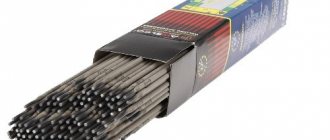
Types of electrodes
Round
The simple “round” type can be used indefinitely. The cross-section of the rod ranges from 3.2 to 19 mm. There are also so-called “round endless” electrodes. Of course, they have strictly limited sizes. However, the efficiency fully justifies the main name.
The diameter of the “endless” elements varies from 8 to 25 mm. Most often they are used when welding using a special machine. Both options are acceptable for “simple” welding work. However, any types of coal models, due to their infusibility, consume little.
There are also several types of such electrodes that deserve separate analysis.
Semicircular
The semicircular electrode usually has a diameter of 10 to 19 mm. Such products are often recommended for cutting metal workpieces. It is semicircular electrodes that are used by most amateur and professional welders. The seam has an optimal shape. Creating an edge with a semicircular electrode is easy.
Rectangular
They are also sometimes called flat - but not everything is so simple. When traders say the word “flat”, they may also mean square. The section size ranges from 8 to 25 mm. Most often, such tools are used when it is necessary to repair a defect in a steel casting. They are rarely used for other purposes.
Hollow
It is not often possible to find this type of electrodes. Their typical size ranges from 5 to 13 mm. It is this solution that is suitable for forming U-shaped outline lines. Hollow structures are also excellently used for vacuum welding. The pressure in the working chamber should not exceed 665 Pa.
Welding pencils
We are talking about a welding rod. The product is a rod resembling a pencil with a diameter of 4 to 15 mm, a length of 7 -20 cm. Only instead of a rod there is an exothermic mixture inside. Such products were used by the military when repairing mats. parts in the field.
Principle of operation
The burning mixture releases a large amount of heat sufficient to melt thin sheet metal or copper cable cores. A thin rod can be set on fire with an ordinary match; thicker ones have a special wick that is ignited with a regular lighter. The burning time of such a pencil is from 20 seconds to 5 minutes. Which is quite enough to weld several twists, naturally observing safety precautions when holding the rod and preventive fire-fighting measures, for example, placing a bucket of water next to it so that in case of a fall the burning rod falls into the water, laying a metal sheet, and preparing a fire extinguisher.
| Attention Bearing Buyers Dear customers, send your questions and requests for the purchase of bearings and components by email or call now: Delivery of bearings throughout the Russian Federation and abroad. Bearing catalog on the website |
Attention Bearing Buyers
Dear customers, send your questions and requests for the purchase of bearings and components by email or call now: +7 [email protected] Delivery of bearings in the Russian Federation and abroad. Bearing catalog on the website
themechanic.ru
Graphite electrode for welding
Due to its technical characteristics, the graphite electrode is easy to cut, consumes more slowly, and does not crack during welding. As practice shows, welding of wire cores is carried out in distribution boxes. The boxes are located quite high, so you will need to use portable welding equipment for welding.
Industrial devices are used for these purposes, the use of which is advisable in a professional sense. If possible, you can assemble the welding machine yourself. However, for most people, inverter-type devices, which are presented in a large assortment in stores, are perfect. They are compact, mobile, lightweight and also have the ability to adjust the welding current you need.
Types of electrodes for welding copper wire cores
When welding copper conductors, appropriate electrodes must be used. We have already mentioned carbon electrodes. There is also a graphite type of electrodes. Battery rods, brushes of commutator motors and similar products made of graphite can be used as an electrode in household use.
Graphite rods are a good replacement for purchased electrodes, with the only exception that they do not have copper plating, but this can be solved by improving the holder. To do this, it will be necessary to use an alligator clip, both for the electrode and for the ground connection. They will not be as bulky as standard ones, so it will be more convenient for you to work in switchboards. Of course, you will need to take care of additional insulation of the handles.
Graphite and carbon electrodes have a general similarity: both have a melting point 4 times higher than the melting threshold of copper itself. Because of this property, the consumption of electrodes when connecting electrical wiring is very low.
Please note that the electrode heats up to a high temperature instantly, so there is a risk of overheating the material being welded, which, in turn, can damage the insulation in the cable. The welder needs to know these factors in order to be careful when installing electrical wiring.
Differences between graphite and carbon electrodes
Despite the similarity of graphite and carbon rods when installing wiring, their characteristics differ:
- The first difference is the price. Graphite products are more affordable;
- if the carbon rod is completely black, then the graphite electrode has a gray-dark color with a metallic tint;
- welding using a carbon electrode requires a certain skill from the welder, since the carbon rod creates an arc of enormous temperature, which can lead to the destruction of the welded twist. At the same time, huge temperature indicators occur at low current. Based on this, carbon electrodes will be useful to a welder with a weak welding machine;
- for those who own an inverter device that is equipped with a current regulator, it is better to use graphite rods. When working with them, less skilled craftsman is required. In addition, the connection of wire cores after their use is characterized by greater strength, better quality, and increased resistance to oxidation than after the carbon welding process.
Assembly instructions
Assembling the device with your own hands will require minimal skills in working with hand tools. For convenience, the manufacturing process should be divided into 5 stages:
- Preparing the body. It is selected based on the dimensions of the transformer.
- Search and installation of a transformer. Checking its performance.
- Selection of power cable. Protection of the device from overload.
- Installation of output terminals. Other connection methods.
- Selection and installation of holder and electrode. DIY alternatives.
Welder body
The easiest way is to use a ready-made housing from any electrical device. For example, from a car charger or a suitable uninterruptible power supply from a computer. It is desirable that the housing be made of dielectric material (plastic, carbolite). This will be a plus in favor of the security of the future device. If none of the above options is suitable, then the easiest way is to make a body from thin sheet iron 1-3 mm thick.
Transformer selection
The required transformer can sometimes be found in stores. Another option is to look for it from friends or wind it yourself.
The primary winding of the transformer is designed for 220 V. The iron is selected based on the overall power of 200-1000 W. Low-power transformers are suitable for welding thin wires, and high-power transformers are suitable for thick ones.
The secondary winding of the transformer is wound with wire from 35 kW. mm, because she will have to experience short circuit currents. It is better to use copper as the material for the output winding. This will reduce heating losses.
Power cables
The 220 V power supply cable is selected based on the power of the transformer. For devices with a consumption of 1 kW, its cross-section is taken to be at least 4 square meters. mm. A thick cable is also better because it is more difficult to break or break during repairs and wiring.
To protect the device, it would be useful to install a fuse or circuit breaker in the primary winding circuit. This way the transformer will be protected from overcurrent.
Terminal Applications
If possible, the use of terminals should be avoided. They tend to become loose and burn over time, especially at high currents in the secondary winding of the transformer. The most reliable connections are made by welding, soldering or crimping.
In some cases, terminals are convenient. For example, at the output of a welding transformer. Using terminals, you can move the device separately from its wires. The main thing is to ensure that during operation the terminals do not oxidize, dangle or overheat. It is permissible to periodically remove dirt using a file.
Electrode holder
Welding is carried out with a graphite electrode coated with a thin layer of copper. This combination provides the good conductivity of copper combined with the heat resistance of graphite. Similar electrodes are commercially available. If you couldn’t find them, you can make them yourself from a graphite brush of an electric motor. It should be taken larger and cut with a hacksaw to the desired size.
Homemade holders for welding. The holder is made of a pair of copper bars and bolts for tightening. The device must securely clamp the graphite electrode.
Spring terminals
Spring clamps are the simplest, most effective and fastest connection. According to user reviews, the most reliable terminals are from the German company Wago. The principle of operation and the design of the terminals can be seen in the picture.
The advantages of this connection:
- Can be used without any special knowledge;
- There is no need for additional core insulation;
- Quick connection, some connections are made by pressing a button or lever on the clamp body.
Flaws:
- Spring terminals can be used for cables with a diameter of no more than 4 mm 2.;
- A 15% safety margin must be taken into account. For example, if the network is designed for 16A, then the terminal block must be at least 20A;
- Also, the disadvantages include their high cost; one Wago terminal can cost about 12 rubles.
Recommended welding current modes for different conductors
The magnitude of the welding current depends on the cross-section size and the number of strands in the twist: the thicker the twisted bundle, the greater the current value must be set on the welding machine:
- 2 cores, cross section of each 1.5 mm² - 70 A;
- 3 cores, cross section of each 1.5 mm² - 80-90 A;
- 2-3 cores, cross section of each 2.5 mm² - 80-100 A;
- 3-4 cores, cross section of each 2.5 mm² - 100-120 A.
The specified welding current modes are indicative. Wires from different manufacturers differ in chemical composition and declared cross-section, and welding devices also differ in their characteristics. Therefore, it is better to select the value of the welding current practically on a small section of the same wire. When choosing a mode experimentally, the optimal one will be when the arc is stable and the tip of the electrode does not stick to the welding site.
For modern inverter-type devices:
- stable welding discharge, ensuring high-quality welding work;
- When welding, liquid metal does not splash;
- the arc does not blind the welder due to the low melting point of copper;
- inverters are not heavy, their dimensions are small, which allows them to be carried to the installation site on a belt.
How can a beginner learn to weld with a welding inverter?
First we learn to light and hold an arc. Feel the edge when to bring the electrode closer to the surface to be welded during combustion so that the arc does not interrupt.
The electrode is ignited in two ways:
- tapping;
- chirping.
The new electrode ignites easily. A slag film appears on the working rod, preventing ignition. You just need to tap longer to break the film.
- To facilitate arc ignition, inverter devices have a built-in Hot Start function.
- If a beginner quickly brings the electrode closer to the surface, the Arc Force function (arc force, anti-sticking) is activated, increasing the welding current, preventing the electrode from sticking.
- If the melting rod gets stuck, the Anti Stick function cuts off the current, preventing the inverter from overheating.