There are a whole lot of metal parts, they differ in their shape, weight, quality, therefore the types of metal cutting will also differ from each other. To manufacture any part, you will need metal material, it can be: welded blanks, plastics, stampings, castings, rolled sections, forgings. Such names can be combined into one group called “blanks”.
In order for the part to meet all specified parameters, the turner or miller must remove all excess metal from the workpiece. Until the desired shape is obtained, the master will process the part using a metal cutting machine or hand-held metalworking equipment. That unnecessary layer of metal removed is called “machining allowance.” This is the whole essence of metal cutting.
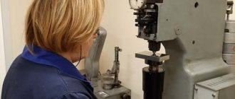
Metal processing
Existing methods of cutting metal
Let's take a detailed look at the main methods of metal cutting, what they are, how they are performed, etc.
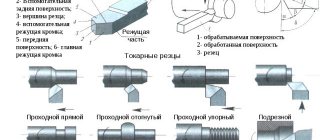
1. Turning (turning). Performed when the workpiece is not too different in size from the desired part. This process can be performed on the following equipment (machines): turning, milling, drilling, grinding, slotting, planing, etc. For this cutting, a lathe cutter is used. The process occurs at a high speed of rotation of the part, which is provided by the cutter. This movement is called the "main". And the cutter moves slowly and progressively, along or across. This type of movement is called the “feed movement.” The cutting speed is determined by the main movement.
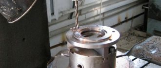
2. Drilling. These are methods of processing metals by cutting, where the name speaks for itself. Happens on any machine where there is a drill. The workpiece is clamped firmly in a vice, and the drill rotates with slow translational movements in one straight line. As a result, a hole appears in the part with a diameter equal to the size of the drill.
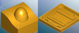
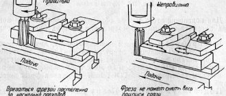
3. Milling. Such methods of processing metals by cutting can only be performed on special tables-machines - horizontal milling machines. The main tool of the machine operator performing metal milling, which makes the main movement, is the milling cutter. The feed movement is carried out in the longitudinal direction of the workpiece; it occurs at right angles to the movement of the machine. The future part is firmly clamped on the table, and it remains motionless all the time.
4. Planing. Occurs on transverse planing equipment and machines. The workpiece is processed with a cutter that performs slow movements in a given direction and back. The main movement belongs to the tool - a slightly curved cutter. The feed movement is performed by the workpiece, and it is not continuous, but intermittent. The direction of the last movement is directly perpendicular to the main one. In this type of machine, the cutting movement is calculated by adding the working and idle strokes.
5. Sanding. The activity is carried out using a grinding wheel on cylindrical grinding machines. The cutting wheel makes rotational movements, and the workpiece receives a linear and circular feed, but if a cylindrical part is turned. When the workpiece is a flat surface, the workpiece receives feed only in the forward direction.
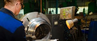
The exhibition held in Moscow “metalworking 2013” amazes with the presence of modern equipment. Photos of the equipment with which are presented in the following story:
Innings
Feed S is the amount (path) of movement of the cutting edge per revolution of the workpiece being processed, or per stroke of the workpiece or tool in the direction of the feed movement, mm/rev, mm/double stroke.
The feed is determined based on the condition of ensuring the required roughness of the machined surface. Usually they work at Spr = (0.20…0.25) mm/rev. High purity is obtained when working at Spr = 0.03…0.05 mm/rev.
These parameters, the cutting mode elements t and S, directly affect the size of the chips removed, as follows:
a is the thickness of the cut layer, the distance between two successive positions of the main cutting edge per one revolution of the workpiece is determined by a = S sinφ;
c – width of the cut layer, distance between the machined and machined surfaces, measured along the cutting surface: b=t/sinφ.
The shaded area is called the cross-sectional area of the cut layer F:
F = t · S = a · b, mm2.
Basic terminology when cutting metals
The depth of cut is the thickness of the metal, expressed in millimeters, which is removed with one movement of the machine. Feed is usually called the distance in millimeters made in one movement of the cutting object or by which it moves in one revolution. Cutting speed is the length, described in meters, that will be needed to operate the machine in a specific period of time. This unit of measurement is usually taken as a minute.
For those who want to personally understand the details, just type in a search engine - metal cutting technology directory.
For any type of cutting, effort must be made to help the tool separate the layer of metal. Such forces are called “cutting forces”; it is this concept that helps to find cutting resistance. The force with which the material resists the tool is called the “cutting coefficient”; it is different for each metal. The size of this value is taken with a cross section of 1 mm².
We have already described above what types of machines there are according to their purpose, but according to the level of automation they are: hydraulic, equipped with program control, automatic and semi-automatic.
There are different methods in metal forming that are used in a wide variety of industries. Do you want to make a metal sauna stove yourself? How to build it with your own hands, read this article.
The final stage of working with metal is its hardening. How to produce it correctly, read the article at https://elsvarkin.ru/texnologiya/texnologiya-zakalki-i-otpuska-stali/ link.
Depth of cut
t – cutting depth, the amount of metal layer removed, measured perpendicular to the machined surface and removed in one pass of the cutting tool:
, mm;
where Dzag – diameter of the treated surface, mm;
d – diameter of the treated surface, mm;
The depth of cut t is usually assumed to be equal to the allowance. During the finishing pass, t should be no more than 1…2 mm.
Figure 4.1 – Cutting elements and geometry of the cut layer
What is each machine intended for?
- Lathes make holes in cylinders and cones. They can be used for threading, drilling or countersinking. The tools of this machine are cutters of different types.
- Drilling machines perform the same operations as lathes, but they can also bore threads or holes. The work is performed using drills, anchors, reamers, taps, and cutters.
- Milling machines are designed to work with flat surfaces or shapes that are complex in design. Such operations are carried out using many blades that the cutter has. This tool also has its own classification.
- Planing machines operate using cutters. They process flat and shaped workpieces, and can plan a trench.
- Grinding machines grind with high precision and perform all finishing work. The tools of such a machine are a beam and a circle.
- Gear cutting machines help cut teeth into conical or cylinder shaped parts.
If you want to read such information in a somewhat expanded form, then you will need a textbook on metal cutting, or a regular publication such as the “magazine of metalworking and machine tool construction.”
What are the types of metalworking tools?
Metalworking tools come in the following types:
- Cutting machines designed to separate metal sheets or any other workpieces into parts. They are made of hardened or alloyed steel, as well as alloys based on them, the hardness of which exceeds the strength of the material being processed.
- Abrasive, used for roughing or finishing workpieces: polishing, grinding, stripping in order to achieve the desired level of roughness. Unlike cutting tools, they can be flexible and ductile. They are made from various materials that are resistant to friction and have high strength.
Cutting tools are only metal, hard, retaining their shape and geometric dimensions during processing and after its completion. The cutting part has a wedge-shaped shape, which allows it to easily penetrate layers of material and remove part of the metal under mechanical influence.
Abrasive equipment can be rigid (circles) or flexible (belts, sandpapers, fabrics). The general similarity is the presence of an abrasive layer on their working surface, which can process the outer layers of the material depending on the force applied. Flexible abrasives allow you to clean non-linear surfaces.
Read also: Connection diagram for 220V compressor electric motor
According to the method of mechanization, tools are of the following types:
- Mechanical ones are intended for manual processing. They are used for one-time or permanent private or industrial use. They are characterized by simplicity of design, low productivity and cost of processing.
- Automatic ones are used for mass production of parts. They provide high processing productivity, functionality, cutting accuracy, and minimize labor costs. They have a complex design, require periodic maintenance, and differ from manual ones in the low probability of producing defective parts.
The process of removing chips by all methods has the same principle. The cutting part, under the influence of the applied force, acts on the surface being processed, cuts into it, deepens and chips or chips are removed.
Chip shear typically occurs at an angle of 135 to 155 degrees. Tool wear and cutting quality depend on the cutting angle and turning of the cutting edge. When processing metal, heating occurs, so it is necessary to choose the optimal speed of action to prevent dulling of the cutting edge.
Manufacturers of metal processing tools
There are manufacturers who have been making high-quality equipment for metal blanks for several decades. At the same time, both domestic and imported companies are represented.
Domestic
The equipment of JSC NIR is most widespread in Russia. To produce equipment, the company uses alloys of special hardness. The main advantages of their products:
- high wear resistance;
- it is possible to quickly change tools;
- there is a nano-coating;
- low sharpening costs.
The Moscow Tool Plant is not lagging behind in terms of performance. Products have been based on world standards for several decades. Using such equipment, you can easily create the most non-standard threads, machine a coupling, pipe and any other part on a lathe.
Imported
Foreign factories produce high-quality tools that are used all over the world. One of the leaders is the Israeli company ISCAR, which produces tools for turning, drilling, and milling.
For processing titanium, aluminum, stainless steel, cast iron, you can use strong and reliable German tools from ARNO.
The top five includes the Japanese company SUMITOMO. They make their equipment from hard alloys, diamonds and CBN. The products are used for turning and milling work of various levels of complexity.
Size differences
When choosing any tool, it is important to pay attention to its size. Files come in 6 classes, which differ in processing accuracy.
Good to know. There are more than 20 types of turning tools. They are divided into left-sided and right-sided.
The dies or dies used to cut threads differ in their measurement system. It can be in millimeters or inches.
Plumbing and repair work
There are plumbing and repair work, which consists of replacing or correcting damaged and worn parts, manufacturing missing parts, assembling components, mechanisms and even the whole machine, performing fitting work and adjusting assembled mechanisms and testing the finished machine. Each mechanic has his own workplace - a small section of the workshop's production area, where there is all the necessary equipment: hand tools for metal processing, instrumentation, auxiliary devices.
The main equipment of the workplace for metalworking is a bench with a vice attached to it and a set of necessary working and control tools and devices. In order for the workplace to be able to move parts or components weighing more than 16 kg, it must be serviced by cranes or lifts. To perform assembly or disassembly work, workplaces are equipped with stands, conveyors, roller tables, special carts or other transport devices.
Assessment of tool cutting qualities
The durability of a cutting tool is measured by the duration of its use - in minutes - between regrinds, while maintaining the wear parameters of the cutting part necessary to perform work with the appropriate quality.
The cutting qualities of a tool are determined by its ability to perform cutting operations on materials. To characterize and compare the cutting properties of a tool most accurately, you should select a number of workpieces of the same type that have been processed by this tool, and identify the main parameters, including:
- tool stroke length;
- calculate the total length of the workpieces and the area of the processed surface;
- volume of chips (cut layer);
- determine the number of resharpenings and the service life of the tool.
What is the purpose of a metalworking tool?
Grinding tools for metalworking are abrasive grains bound with special binding materials. The shape of the grains is distinguished by the presence of sharp edges of different sizes, which, when touching the metal, are capable of removing layers of a certain thickness from it.
Grinding tools include: bars, sandpaper, fabrics with special coatings, wheels.
Cutters, cutters, drills, taps, and broaches can be used for cutting. They are selected in such a way that their hardness is higher than that of the materials being processed.
Cutting metal 4–7 mm thick is performed with metal scissors or a jigsaw, or a hacksaw. It is convenient to cut a layer from 5 mm with a grinder.
Handles, hammers, sledgehammers, and shaped hammers can be used in metalworking or blacksmithing work. Handbrake handles are used to determine the force of impact and indicate the exact location for processing. Sledgehammers are used for cold deformation of workpieces.
Artistic processing of metals can be done with a shaped hammer. It allows you to knock out relief surfaces due to the presence of a curved or wide flat and rounded striker.
The following equipment is used for minting:
- ratchets, hooks for basting relief blanks;
- boboshniks, kanfarniks, loschatniks to create the necessary relief;
- cuts for chasing lines, semicircular or curved lines;
- figured coins (tube, boot, iron, kanfarnik, purushnik, loshchatnik), used to create a series of identical small detailed patterns.