Marking
| Marking is an operation in which contour lines (marks and recesses) are applied to the part being manufactured (or repaired), defining the boundaries of processing. The marking is called planar when all its lines lie in the same plane, and spatial when the marking lines are drawn in different planes. To carry out marking, you must have a marking plate and a set of special tools and accessories, including: an angle plate (setting square), prisms, measuring squares, a gauge with accessories or an ordinary gauge, i.e. a tripod with a scriber, a caliper with double-sided jaws, caliper with one-sided jaws, measuring ruler, calipers and bore gauge, protractor, marking compass, center punch, screw jacks, scriber, flat, prismatic and wedge-shaped pads, hammer, clamps. For particularly precise marking work, measuring (plane-parallel) end tiles are also used. Read also: Why Berkut left Aria |
html for planar markings
Work must be performed on a flat and comfortable surface. For this purpose, marking tables are used:
- woody;
- Key.
strict conditions for the quality and design of tables:
- durability and strength. To ensure strength, the legs are connected to the table by horizontal bars. It is recommended to place large-scale marking plates on jacks.
- Sufficient area for work surface. Regular tables have lengths: sizes 2000–3000 mm; width 4000–height mm; 5000 700–1000 mm. The surface area of the table should be suitable for the dimensions of the sheets, tapes, and strip material.
- Convenience. The tables are equipped with different loads:
- devices for fixing lung sheets with prisms;
- material for installing pipes;
- fastening clamps for metal sheets;
- rectangular and wedge-shaped for gaskets for installing profiles and other parts.
work The place must be guaranteed with all the necessary planar marking tools. The table contains a list of the necessary tools and specific tips for using them.
| Tool | Function | Design requirements | Application by Tips | ||
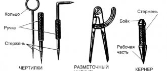
| Scriber | drawing marked lines on thin | · steel rod blanks; · one end is sharpened at 45 degrees, the other is bent into a ring; The sharp end is hardened | · to obtain thin points, the marks must be hard and sharp; · while the scribe is working, deviate from the ruler in the direction it is moving, the tip should be regularly pressed against the outline | ||
| line | drawing contours parallel to the edges of the material | · sheet: copper or steel; · the presence of a graphite pencil in the working part | Reismus | · checking the layout blanks; · carrying out parallel risks | · a stand with a scriber at the required height; · the fixation height is measured using a square |
| Kerner | · construction of centers of circles of holes or; · drawing holes on the marking lines | · hard - material steel; · dimensions: diameter 8-13 mm, length 90-end mm; · 150 is sharpened at 60 degrees; · there are automatic and manual (set marks of the same size) | work for automatic center punch hammering not metalworking | ||
| hammer required | percussion instrument for use | hammers weighing 50 - 200 g | work with the lungs is performed by movements communicated by bending the hand “from the angles” | ||
| shoulder | · construction and control of angles; · recovery preferred | perpendicular material - metal | · it is advisable to have angles of 30, 45, 60 degrees; · a square with a shelf is used to check for the correct placement of parts on the plate | ||
| goniometer with protractor | marking corners and checking mating preferred | scratch material - metal | You can fix the position of the hinge with a screw | ||
| Compass | · construction of circles, transfer; · arc dimensions from ruler to workpieces | It is recommended to harden the legs with compasses | the point of the compass is placed firmly in the hole | ||
| Marking plate | · Serves as a working surface; · used for equipment storage | · located horizontally; · must be clean and dry | placed on cabinets, stands with drawers, tables | ||
| Templates, simplification | stencils and acceleration of marking of similar parts | durable steel templates | ensure a tight fit of the workpiece to the template | ||
| Vise | tool for fastening small parts | ensuring smooth efforts when | For tightening fine work, a small step is recommended; for coarse clamping, a wide step is recommended. |
Application
Using a core, you can make marks on any surface. It is advisable to use it when working with smooth materials. These are tiles, polished surfaces. Most often it is used when drilling metal. Therefore, core samples are often referred to as metalworking tools.
Masons also actively use it. Special mason cores have been created for this purpose. They are not much different from locksmiths. They are often powder coated in a bright color to make them easier to find if lost.
Stage 2. Drilling
The drilling process must be thought out based on the task and material of the part.
Holes marked with a core are drilled on drilling machines, as well as with rotary hammers, ratchets (for large diameters), hand and electric drills.
At this stage, it is important to remember that friction causes drills to become very hot and can break or become deformed. For cooling when drilling steel, brass or copper, use mineral oil or soapy water; for aluminum, kerosene is added to it
No cooling is required when drilling bronze and cast iron.
To avoid breaking the drill at the exit from the hole, reduce the number of revolutions before finishing drilling. If you need to drill a hole with a large diameter, first use a narrow drill, then a wide one.
Marking boards
Marking plates have a ribbed design, which gives them rigidity with a relatively low weight.
The working surfaces of marking plates must be precisely machined. To avoid deformation of the slabs during their operation, the castings are subjected to aging (exposure to air for a long time) between roughing and finishing processing.
On the upper surface of the marking plate (Fig. 1, a), in the absence of machine grooves, longitudinal and transverse grooves with a depth and width of 1-2 mm are cut so that the entire surface of the plate is divided into square sections.
RGPPU
Educational elementName
Methods for planar marking of sheet material.
Professional area
Locksmith work
Code Publication date Page5
– using a marking line, connect the corresponding risks;– using a square, draw parallel lines from the obtained points at a distance (B) from the center line to the second edge of the workpiece.
As a result of marking on the surface of the sheet, a contour of the marked figure is obtained, the dimensions of which are controlled using a ruler.
Template markup
produced in the following sequence:
– place the sheet prepared for marking on the marking plate;
What you need to know about the center punch
When choosing a core sample, you need to remember several important points about this type of instrument.
Firstly, it does not matter at all what cross-sectional shape the tool rod has.
It is much more important to pay attention to its other characteristics. Secondly, you should buy a device based on the diameter and type of drill with which it will be used
Secondly, you should buy a device based on the diameter and type of drill with which it will be used.
Thirdly, if you plan to use a center punch when working with soft metals, it is better to choose one with a smaller sharpening angle and vice versa.
Decorative coating material
One of the main aspects in the design and construction of such facilities is the creation of surface drainage. The layout of the flat surface in a vertical position will allow you to quickly remove and collect water, subsequently falling precipitation, to a place determined by the project and direct it to the storm network. The choice of material is made taking into account physical and mechanical properties.
Is it difficult to figure it out on your own?
Try asking your teachers for help
Solving problems Tests Essays
When constructing surface objects of all classes, it is necessary to take into account resistance to atmospheric factors such as snow, rain, frost, heat. Such paths are designed more for pedestrian paths, so the quality of the surface must be perfectly smooth and non-slip. Depending on the functionality of the path, decorative coating plays an important role. In some places, river or sea pebbles are used to cover the top layer of the path. A frequently used surface is asphalt, as it is considered durable, practical and durable. Roads and trails in parks that see heavy visitor traffic often have a crushed stone base, but the majority of the surfaces are made of stone. Areas with minimal load are made in the form of stone slabs with sand joints.
Applying marks
The standard regulates the procedure for drawing marking lines:
- horizontal;
- vertical;
- inclined;
- curvilinear.
Applying curved elements after straight ones provides another opportunity to check their accuracy. The arcs must close the straight lines, the interface must be smooth.
Tools for marking
Direct marks are carried out with a well-sharpened scriber, without tearing off, in one step. At the same time, the scriber is tilted away from the ruler or square so as not to introduce distortions.
Parallel lines are drawn using a square and moving it along the reference ruler to the required distance.
If the workpiece already has holes, then a special tool, a center finder, is used to attach marking lines to them.
Center finder
In order to mark inclined lines, use a marking protractor with a hinged ruler fixed at its zero point.
Marking protractor
For particularly precise markings in plumbing, calipers are used. They allow you to measure distances and scratch marks with an accuracy of hundredths of a millimeter.
RGPPU
Educational elementName
Methods for planar marking of sheet material.
Professional area
Locksmith work
Code Publication date Page5
– on half the side of the workpiece, using a marking compass, draw a longitudinal center line;– from the base side of the workpiece at a given distance (A) draw a line perpendicular to the center one;
-spread the jaws of the compass to a distance equal to half the size (B) and lay marks on the base side on both sides of the center line, the distance between which will be equal to (B).
-spread the jaws of the compass to a distance equal to half the size (B) and lay marks on a perpendicular line on both sides of the center line, the distance between which will be equal to (B).
What is a marking operation?
It should be immediately clear that marking does not necessarily mean fixing the distance from one point to another when constructing a particular structure. As production and construction standards become more complex, the manufacturability of marking processes also increases. During this action, a foreman at a construction site or an operator on a production line can determine the parameters of the workpiece, the characteristics of its location relative to other objects, etc. A modern marking tool allows you to record indicators such as length, width, height and angle. Some models such as squares are also focused on initially determining how well an object, its parameters or location meet the requirements. As for the marking process, it mainly involves manual handling of measuring and marking devices. The user, in turn, is required to be attentive, accurate and thorough in removing and recording data.
Classification of planar objects
The classification of planar objects is based on the significance of the layout of the total area and the direction of its use. Planar objects are divided into 6 classes according to the level of complexity and purpose.
The first class, as a rule, includes pedestrian paths and alleys; within the framework of the entire project, they allow you to move comfortably throughout the entire area of the park area. Such paths also help to connect the main entrance and the main nodes of the common area. Pedestrian paths and alleys provide for the movement of visitors in two directions. The sizes of such objects vary; on average, the width can be from 5 to 60 meters, but this in turn will depend on the total area of the object and the number of visitors; traffic intensity reaches up to 600 people per hour. Occasional passage of vehicles is allowed. The operation of these types of facilities is intended for approximately a year of use.
The second class of planar objects includes secondary roads and alleys, in the form of branches from the main road. Thus, they distribute people throughout the entire area, thereby ensuring movement across all functional areas, approach to sites, structures, flower beds, the width of which ranges from 2.5 to 12 meters. Secondary use alleys accommodate up to 300 people per hour and operate for approximately a year or a season, depending on the surface materials used. Also, there are pedestrian paths that are intended for walking and their location connects them with roads and trails. They belong to the third class of planar objects, with a width from 0.75 to 3.5 meters. Pedestrian activity for such objects is provided for in a minimum number of visitors.
The fourth class includes paths for cyclists, in the form of connected routes, the location of which is provided along the main and other paths. The tracks for horse riding are classified as fifth class. The design of these types of routes is carried out in large parks and forest parks, ranging in width from 2.5 to 6.5 meters. Roads for economic purposes are classified as the sixth class of surface objects, with limited vehicle traffic. Movement within a park or square, on passenger transport, holding exhibitions, opening trade, installing attractions is allowed under the conditions that the total area of the territory is not less than 300 hectares.
Marking. Marking a workpiece or part
Marking is the operation of applying lines (so-called marking marks) to the workpiece being processed or the part being repaired, defining the contours of the part or the area to be processed.
Marking of parts is used mainly in small-scale production of parts and when carrying out metalwork repair work.
To carry out various marking work, a mechanic must have special measuring and marking tools (rulers, thickness gauges, scribers, punches, etc.).
To install, align and secure the marked parts, use a set of special devices (linings, prisms, squares, etc.).
Marking is done on marking plates, on which all fixtures and tools are placed.
Marking boards
Marking plates have a ribbed design, which gives them rigidity with a relatively low weight.
The working surfaces of marking plates must be precisely machined. To avoid deformation of the slabs during their operation, the castings are subjected to aging (exposure to air for a long time) between roughing and finishing processing.
On the upper surface of the marking plate (Fig. 1, a), in the absence of machine grooves, longitudinal and transverse grooves with a depth and width of 1-2 mm are cut so that the entire surface of the plate is divided into square sections.
Large marking plates are installed on special stands (pedestals) with drawers for storing tools. Small marking plates are placed on wooden stands and installed directly on workbenches.
The height from the floor to the working surface of a marking slab of small or medium sizes is 800–900 mm, and of large slabs – 700 mm.
The marking plate must have free space to walk around and to be able to work from either side.
Checking the flatness of the marking plates is carried out using an accurate ruler and feeler gauge. To do this, the ruler is placed with its working surface on the working surface of the marking plate. The gaps between these surfaces are controlled with a feeler gauge. The thickness of the probe, which passes into the gap between the ruler and the marking plate, should not exceed 0.03–0.05 mm.
The correctness of the working surfaces of scraped marking plates (Fig. 1, b), intended for precise marking and verification work, is checked for paint using a straight edge. The number of spots in a 25x25 mm square must be at least 12.
Rice. 1. Marking boards
Equipment
In order to install the part on the working plane of the marking plate, support pads, prisms, jacks, special devices, cubes and squares are used, which have precisely machined prismatic and vertical surfaces perpendicular to the surface of the plate. Shims are also used to protect the working surface of the marking plate from damage by the untreated (black) surfaces of the parts being marked.
Flat (Fig. 2, a) and prismatic (Fig. 3) pads are placed directly on the working surface of the marking plate.
Rice. 2. Pads for installing the part on the marking plate
Rice. 3. Prism (a) and square (b) for installing parts
Parts that have a flat base, a flat end, or three supports spaced at a maximum distance along the dimensions of the part must be installed for marking on three pads selected in height.
If it is necessary to orient the part in a horizontal plane, then select pads or a set of pads for the supports, in which the part will take a horizontal position. In this case, it is also convenient to use height-adjustable pads. In Fig.
2, b shows an adjustable lining, which is adjusted in height by rotating screw 1, which moves wedge 2 along wedge 3. On the side surface of the lower wedge there is a scale that allows you to more accurately set the height of the lining.
Cylindrical parts are placed on prismatic supports with triangular cutouts (Fig. 3, a). A set of auxiliary tools usually contains several of these pads with the same cutouts.
For ease of marking, the part can be fixed to a square (Fig. 3, b) installed on the marking plate. The shelves of the square have through holes through which the part can be attached to the square.
Stage 3. Cutting internal and external threads
In metalworking work, threads are most often applied by hand.
Threading is the process of obtaining helical grooves on the internal or external surface of a workpiece.
The thread consists of elements such as:
- Profile is the cross-sectional shape of a part of a thread (turn) formed during a full revolution.
- Pitch is the distance between turns.
- Height - the distance between the extreme points of the thread.
- Angle - determined between the two sides of the profile.
- Outer diameter - the largest diameter of the thread at the top point.
- Average diameter is the distance between two lines that run parallel to the axis of the bolt, at different points from the bottom of the thread to the top of the thread.
- Internal diameter is the smallest distance between opposite thread bases. Measured in a direction perpendicular to the thread axis.
There are also 3 types of thread profiles:
- triangular or fastening;
- trapezoidal;
- rectangular.
The first is cut into nuts, bolts or studs to fasten the parts together. The second and third are on lifts, jacks and screws to transmit movement along the axis.
External threads are cut manually using dies, knobs and clamps, as well as on machines. The oil-lubricated part is clamped in a vice, a clamp with dies is placed on its end, which cut into the workpiece to a depth of 0.2–0.5 mm. Then the die is turned 1–2 turns to the right and left along the length of the part. At the last stage of carving, the blanks are returned to their original position, the dies are cut even deeper and the final cutting is applied.
To apply internal threads, use a cylindrical or conical tap - a steel screw with grooves to create cutting edges. The part is secured in a vice, and the tap is placed in a driver, which is rotated clockwise with periodic pressure.
Planar marking techniques
A prerequisite for the correct application of markings on flat surfaces is their high-quality preparation. Preparation procedure:
- Using steel brushes, remove dirt, scale, and traces of corrosion from the surface of the workpiece.
- Check the workpiece material for defects: cavities, cracks, blisters.
- If defects are identified, they should be measured and measures taken to remove them.
- If it is not possible to remove defects, then a marking plan should be drawn up so that they are removed from the surface during processing.
Before performing planar markings, it is recommended:
- Analyze the drawing of the part, its purpose, characteristics and dimensions.
- Develop a marking plan.
- Using reference books, determine processing allowances.
- Paint the surface.
The purpose of coloring is to ensure the clarity of the marks applied. When painting a small part, it is held at an angle in the left hand. Using a paint brush, apply paint thinly in cross movements. Large pieces are painted using a roller or spray.
Recommendations for staining are given in the table.
| Surface type | Coloring agents |
| any types of surfaces, except hot-rolled steel and non-ferrous metals | quick-drying water-based paints, alcohol varnishes |
| cast iron or steel workpieces | copper sulfate: · in pieces; solution (3 teaspoons per 200 g of water) |
| untreated black blanks | a solution of chalk in water (the consistency of thick milk) with the addition of drier or linseed oil |
The technique used for applying planar markings depends on its purpose, the material on which the lines are applied, and the shape of the parts being marked.
Marking work can be performed:
- according to the drawing - all elements of the part are transferred from the drawing to the material;
- according to a template - the contours of the part are outlined on the material along the contours of a pre-made pattern, template or stencil;
- according to a sample - used when there is no drawing and template, dimensions are taken from a sample of the part being replaced;
- in place - carried out during assembly or adjustment to the size of assembly units of dimensional parts.
If a drawing is used during work, the order of marking is as follows:
- Carefully study the drawing, find out the material of the part and the process of its manufacture.
- Establish methods and procedures for applying lines and cores to the material.
- The dimensions shown in the drawing should be marked using special marking tools and measuring instruments. It is not recommended to transfer dimensions from the drawing using compasses, even if the drawing is made on a scale of 1:1. This is due to the fact that the dimensions of the paper on which the drawing is applied may change as it dries.
- Set the base from which the marking will be carried out. The base can be:
- edges of the material to be marked;
- previously drawn lines, for example, axial, center.
- The order of drawing lines:
- in the horizontal direction;
- in the vertical direction;
- arcs, fillets, circles;
- slanted lines.
- Mark the lines.
- Check the presence of all lines from the drawing on the marked surface.
Techniques for high-quality marking:
- Marks on steel workpieces are made with a scriber. On sheets of aluminum-based alloys, all internal lines, to avoid damage to the coating, are drawn with a pencil, contour lines with a scriber. For cleanliness, the line is drawn only once. If the line is poorly drawn, then this area should be painted over, allowed to dry and the line drawn again.
- When working with a center punch, with your left hand, place it with its pointed end exactly in the required place, tilting it away from you and pressing it to the intended location. Afterwards, the punch should be quickly brought to a vertical position and lightly hit with a hammer. When applying the punch, the following nuances should be taken into account:
- the centers of the punches must be located clearly on the lines, so that after processing operations half of the hole remains on the workpieces;
- Be sure to mark the intersections of marks and roundings;
- on short marks, holes are made every 5-10 mm, and on long ones - 20-100 mm;
- the circle is marked at the intersection of the axes;
- on the treated surface, holes are placed at the ends of the marks;
- on cleanly processed surfaces, the lines are not marked; they are extended to the side edges, where the holes are placed.
- Perpendicular lines are drawn using a square. The workpiece is placed in the corner of the work table plate and secured with a weight. To mark the first line, the shelf of the square must be attached to the side surface of the slab. Then the square is moved to a perpendicular surface and a second line is drawn.
- When applying markings according to the template, you must use a properly sharpened scriber. It should be installed so that the generatrix of the cone moves smoothly along the contour lines of the template. The accuracy of the work is influenced by the conditions of contact of the template to the surface.
- When marking according to a sample, all dimensions are transferred from the used part to the workpiece. Before starting work, it is checked for sufficient allowances; the holes in the workpiece are closed with center plugs. The following is the sequence of actions:
- place the workpiece on the plate next to the part, taking into account the uniform distribution of allowances on the workpiece;
- gradually transfer all dimensions from the part to the workpiece;
- synchronously changing the positions of the workpiece and the part, transfer all dimensions with a thicknesser;
- using a square to check the compliance of the installation of the part and the workpiece along the lines drawn in the previous position;
- The marking should be completed by marking the marks.
Tools for flat marking
Work must be performed on a flat and comfortable surface. Marking tables are used for this purpose:
- woody;
- iron.
Key conditions for the quality and design of tables:
- Strength and durability. To ensure strength, the table legs are connected by horizontal bars. It is recommended to place large-scale marking plates on jacks.
- Sufficient surface area for work. Conventional tables have dimensions: length 2000–3000 mm; width 4000–5000 mm; height 700–1000 mm. The surface area of the table should be suitable for the dimensions of the sheets, tapes, and strips of material.
- Convenience. Tables are equipped with different devices:
- weights for fixing sheets of light material;
- prisms for installing pipes;
- clamps for securing metal sheets;
- rectangular and wedge-shaped gaskets for installing profiles and other parts.
The work site must be guaranteed with all the tools necessary for flat marking. The table provides a list of the necessary tools and certain tips for working with them.
| Tool | Function | Design requirements | Tips for use | ||
| Scriber | drawing marked lines on workpieces | · thin steel rod; · one end is sharpened at 45 degrees, the other is bent into a ring; · the sharp end is hardened | · to obtain thin marks, the tip must be hard and sharp; · during operation, the scriber is deviated from the ruler in the direction of its movement; it should be regularly pressed against the ruler with its tip | ||
| Outline | drawing contours parallel to the edges of the sheet | · material: copper or steel; presence of a graphite pencil in the working part | Reismus | · checking the location of workpieces; · carrying out parallel risks | · stand with scriber fixed at the required height; · fixation height is measured with a square |
| Kerner | · construction of centers of circles or holes; · drawing holes on the marking lines | · material - hard steel; · dimensions: diameter 8-13 mm, length 90-150 mm; · the end is sharpened at 60 degrees; · there are manual and automatic (set marks of the same size) | The automatic center punch does not require a hammer to operate | ||
| Locksmith's hammer | percussion tool for punching | use hammers weighing 50 - 200 g | the work is performed with light movements conveyed by bending the hand “from the shoulder” | ||
| Squares | · construction and control of angles; restoration of perpendiculars | preferred material - metal | · it is advisable to have squares with angles of 30, 45, 60 degrees; · a square with a shelf is used to check the correct placement of parts on the plate | ||
| Protractor with protractor | marking corners and checking mark alignment | preferred material - metal | The position can be fixed with a hinge screw | ||
| Compass | · construction of circles, arcs; Transfer of dimensions from ruler to workpieces | It is recommended to harden the legs of the compass | the tip of the compass is installed strictly in the punched hole | ||
| Marking plate | Serves as a working surface; · used for equipment storage | · located horizontally; · must be clean and dry | placed on cabinets, stands with drawers, tables | ||
| Templates, stencils | simplification and acceleration of marking of similar parts | durable steel templates | ensure a tight fit of the template to the workpiece | ||
| Vise | tool for securing small parts | ensuring smooth tightening efforts | For fine work, a small step is recommended; for coarse clamping, a wide step is recommended. |
Marking techniques
The following techniques are used in plumbing:
- According to the template. Used in case of small-scale production. The template is made from rolled metal, the entire batch is marked (or even processed) through once marked slots and holes in this sheet. For parts with complex shapes, several templates can be made for different planes.
- Following the example. The dimensions are transferred from the part - the sample. It is used in the manufacture of a new part to replace a broken one.
- Local. Used in the production of complex multi-component products and structures. Blanks are placed on a plane or in space in the order in which they enter the final product and are marked together.
- Pencil (or marker). Used for workpieces made of aluminum alloys so that the scriber does not destroy the passivated protective layer.
- Accurate. It is done using the same methods, but special precision measuring and marking tools are used.
Techniques for marking metal parts
The selection of techniques is carried out in accordance with design and technological instructions.
Functional purpose of planar objects
- The adult recreation area is intended for cultural short-term pastime or board games;
- The territorial zone for children is intended for active pastime of children of different ages;
- Sports grounds are used for sports and gymnastic exercises;
- The commercial area is intended for household needs and with the use of garbage containers and bins.
- An area for walking dogs, provides for safe walking and training of pets in an urban setting;
- Car parking area - there is a special area where you can park your vehicle for a while.
RGPPU
Educational element
Name
Methods for planar marking of sheet material.
Professional area
Locksmith work
Code
Publication date
Page
10
In the eighth task, establish the correct sequence of marking sheet material according to the template, placing numbers in empty windows.
Tracing the contours of the template using a scriber
Laying the template on the sheet prepared for marking and pressing it to the sheet
Laying the sheet prepared for marking on the marking plate
In the ninth task, establish the correct sequence of punching the marking lines by placing the numbers in the empty windows.
Installing a punch with an inclination away from you onto the marked line
Punching using light hammer blows on the blunt end of the punch
Giving the center punch a vertical position
RGPPU
Educational elementName
Methods for planar marking of sheet material.
Professional area
Locksmith work
Code Publication date Page5
– place the template on the sheet and press it tightly to the sheet;– trace the contours of the template using a scriber and remove the template from the sheet.
As a result of marking on the surface of the sheet, the outline of the template is obtained.
Punching of marking lines
In the process of marking the workpieces, it is necessary to mark the marked lines.
Punching of marking lines is carried out in the following sequence:
– the punch is tilted away from you and the sharp end is placed on the marked line so that the tip of the punch is located exactly on the marked line.
RGPPU
Educational elementName
Methods for planar marking of sheet material.
Professional area
Locksmith work
Code Publication date Page7
– the center punch is given a vertical position;– the marking lines are punched using light hammer blows on the blunt end of the punch in compliance with the following rules:
A = 10 – 50 mm!
1. On straight lines, cores are placed at a distance of 10 - 50 mm from each other.
A = 5 – 10 mm!
2. On short lines, corners, bends, cores are applied at a distance of 5 - 10 mm from each other.
Punching is a must!
3. At the intersections of lines, curves, and centers, applying cores is mandatory.
RGPPU
Educational elementName
Methods for planar marking of sheet material.
Professional area
Locksmith work
Code Publication date Page9
In the sixth task, establish the correct sequence of marking sheet material from the base side of the sheet, placing numbers in empty windows. Applying a marking mark with a scriber Applying a square to the mark so that one of its sides passes through the mark and is parallel to the edge of the sheet Repeating the marking steps on all sides of the sheet Laying the sheet prepared for marking on the marking plate Drawing a line through the mark parallel to the edge of the sheet and located on at a given distance from the edge of the sheet Determining the position of the first mark using a marking rulerIn the seventh task, establish the correct sequence of marking sheet material from the center line, placing numbers in empty windows.
Drawing longitudinal lines using a square
Connecting the resulting marks using a ruler and scriber
Drawing a longitudinal center line using a marking compass
A mark on the base side on both sides of the center line of the marks, at a given distance between them
Drawing a line perpendicular to the center line at a given distance
Laying the sheet prepared for marking on the marking plate
Marking marks on a perpendicular line