Machining holes on broaching machines
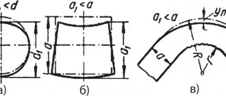
Fig. 194. Shapes of holes processed by broaching.
Hole broaching is widely used in mass, large- and medium-scale production. Broaching is used to machine cylindrical, splined, and other shaped holes.
For broaching, machines are used that can be divided into the following groups:
1) mechanical and hydraulic;
2) horizontal and vertical;
3) single- and multi-spindle;
4) pulling and pushing.
Mechanical broaching machines with mechanical feed appeared in 1905 with gear drive through a rack. These machines were manufactured with a tractive force of 1000 to 5000 kg, which was later increased to 60,000 kg, and with a speed of 1 to 3 m/min. Even manual broaching machines with a traction force of 350 kg and a stroke length of 375 mm for grooves with the largest section of 2X4 x 30 mm were manufactured with a rack and pinion mechanism.
The rack and pinion mechanism did not provide a smooth, quiet operation, which greatly affected the operation of an expensive tool - broaches; therefore, the rack and pinion mechanism began to be replaced with lead screws, which represent a more uniform and quiet traction mechanism (Fig. 195).
It works as follows. From the drive pulley, rotation through gear A is transmitted to gear B, which, by rotating nut B, causes the screw to move; the screw pulls the broach. Reverse accelerated motion is carried out through gears G and D.
Fig. 195. Mechanical broaching machine with drive through a lead screw.
Broaching mechanical machines are also manufactured, in which the traction force is carried out by rotating two lead screws (Fig. 196), transmitting movement to a slide with a broach fixed in them.
Fig. 196. Broaching mechanical machine with two lead screws.
Currently, mechanical broaching machines are being replaced by more efficient hydraulic machines with hydraulic feed, which gives a calmer and more uniform broaching stroke compared to mechanical machines (Fig. 197).
Fig. 197. Broaching machine with hydraulic feed.
The machines are manufactured with operating speeds of up to 12 m/min and return speeds of up to 18 m/min or more.
In fig. 198 shows a vertical broaching machine;
these machines occupy a floor area approximately two to three times smaller than horizontal ones: the product is more convenient to install, the part is removed automatically; with this machine there is no need to move the broach after broaching to its original position, since it is automatically secured either to the upper end or to the lower end.
Fig. 198. Vertical broaching machine.
The use of two and three spindle vertical broaching machines allows you to broach 2-3 parts simultaneously. Horizontal two-spindle machines are used for special parts, such as an engine connecting rod, when two holes are drawn simultaneously.
In fig. 200 shows the installation of the part on a rigid support; This installation can be used when the end is cut perpendicular to the axis of the hole.
Currently, a common method of installing a part on a ball joint (Fig. 201), which allows you to install the product without a cut end or a hole cut not perpendicular to the axis.
When using a ball joint for parts with one cut end, the part is supported on the other raw end; In this way, the broach teeth will cut into the machined end and, as a result, will become less dull.
Fig. 200. Installation of a part on a broaching machine (on a rigid support).
Fig. 201. Installation of a part on a broaching machine (on a ball joint).
Simultaneous broaching of three products increases the productivity of the machine.
Simultaneous broaching of several products should also be used if the length of the product is less than 2-3 broaching steps. To prevent broach breakage, the length of one or more simultaneously broached products should not exceed 6-7 broaching steps.
In products whose length exceeds 6-7 steps, it is necessary to provide a recess in the middle of the hole (Fig. 203), the length of which is determined from the following ratio:
Fig. 203. Determining the length of the groove.
Production of broaching spiral grooves (Fig. 204) by rotating the broach by a certain amount during broaching.
Fig. 204. Pulling spiral grooves.
The broaching of keyways in cylindrical and conical holes is very widely used; The operating diagram is shown in Fig. 205 (A - for cylindrical holes, B - for conical holes).
In fig. 206 shows the location of four broaches while simultaneously pulling four grooves in the gear crown for rivets.
Broaching of short products, as well as calibration of long products, used after heat treatment (with Brinell hardness below 400 kg/mm2), is carried out by short broaches on hydraulic or manual presses. This operation is called stitching.
Fig. 205. Scheme of drawing a keyway in cylindrical and conical holes.
Fig. 206. Arrangement of four broaches for simultaneous broaching of four grooves in the gear ring.
In fig. 207 shows sewing a square hole in a socket wrench with preliminary drilling of a round hole. In the same way, hexagonal holes are stitched in the heads of bolts for small diameters; For large diameters, stitching is carried out in a hot state.
Cutting conditions when pulling medium-hard steel:
Fig. 207. Sewing a hole in a socket wrench.
Cutting conditions for cast iron approximately correspond to those for steel. Broaches made of cast iron are not widely used due to rapid wear of the teeth.
Broaching is usually used for cylindrical and spline holes after a drill or countersink.
The broaching method is becoming increasingly widespread not only in large-scale and mass production, but also in medium-scale production, replacing chiselling on slotting machines in the manufacture of keyways and reaming holes on drilling and turret machines. A slotted hole can only be made by broaching, since when chiseling it is very difficult to achieve the required accuracy, even with metalwork finishing, taking 30-40 times more time.
Drilling holes
In mass, large-scale and medium-scale production, broaching of holes of cylindrical, spline and other shapes is widely used.
Cylindrical holes are drawn after drilling or countersinking. Broaching replaces the reaming of holes on drilling and turret machines.
To broach cylindrical holes, use round broaches and broaches, which ensure processing of holes with an accuracy of class 2 and Ra = 0.32-5 µm
Square, single-key, and splined broaches are used for machining holes of appropriate shapes.
Firmware is used to perform calibration operations, as well as to process blind holes. The broaches are pushed through the hole and, unlike broaches that work in tension, they work in longitudinal bending. Firmware length 150-300 mm
they are much shorter than broaches.
Machines used for broaching are divided into: 1) mechanical and hydraulic; 2) horizontal and vertical; 3) single and multi-spindle.
Mechanical broaching machines have a mechanical feed carried out by a rack and pinion pair or a lead screw. The rack and pinion mechanism does not provide a smooth, quiet operation, which has a bad effect on the broaching operation. The lead screw gives a more uniform and quiet drawing stroke.
Broaching mechanical machines come with two lead screws, which, when rotated, exert traction by transmitting movement to a slide with a broach attached to them. Mechanical broaching machines are increasingly being replaced by high-performance hydraulic machines, the hydraulic feed of which gives a quieter and more uniform broaching stroke compared to mechanical machines.
Domestic horizontal broaching machines develop a traction force of 10,000 kg
(98,060
n)
at operating speed 1.5–13
m/min:
20,000
kg
(196,120
n)
at operating speed 1.5–11
m/min,
40,000
kg
(392,240
n)
at operating speed 1.0 —6.8
m/min,
100,000
kg
(980,600
n)
at an operating speed of 0.3–3.7
m/min.
Vertical broaching machines occupy a significantly smaller area than horizontal ones (about two to three times). On these machines it is more convenient to install a part for processing; part removal can be automated; After broaching, there is no need to move the broach to its original position, since it is automatically secured alternately to the upper end and then to the lower end.
Rice. 20. Installation of parts when pulling.
A
— on a rigid support: 1 — frontal part of the machine;
2 — support washer; 3
- workpiece;
4 -
broach;
b - on a ball joint: 1 - spring; 2
— support washer;
3 — ball joint; 4
- workpiece; 5 - broach
Two- and three-spindle vertical broaching machines allow you to broach 2-3 parts at the same time.
To simultaneously broach two holes in one part [for example, in an engine connecting rod], special horizontal or vertical two-spindle broaching machines are used.
Push stitching machines are used to perform calibration operations. The stitching of through and blind holes is usually carried out using hydraulic, pneumatic, mechanical and manual presses.
Installation of the part for broaching on broaching machines is carried out on a rigid or ball support. Installation of the part on a rigid support (Fig. 20, a)
used when the end of the part is cut perpendicular to the axis of the hole. If the end of the part is not trimmed (black, untreated surface) or is trimmed not perpendicular to the axis of the hole, the part is installed for pulling on a ball joint (Fig. 20, b).
When using a ball joint for parts with one cut end, the part is supported on the other raw end; In this way, the broach teeth will cut into the machined end and, as a result, will become less dull.
Pulling multiple parts at the same time increases machine productivity. If the length of the hole in a part is less than 2-3 broaching steps, you should pull the hole in several parts at the same time.
The main time for broaching processing is determined by the following formula:
,min
where L is the length of the working part of the broach in mm; l
— length of the drawn surface of the part in mm;
Vp—cutting speed (working stroke), m/min; Vo.x.
— reverse speed in
m/min.
The reverse speed is assumed to be 2-3 times higher than the working speed.
By broaching, you can make spiral grooves in the hole, for which, during broaching, the broach is rotated at a certain angle.
Broaching (patterns, tools, application)
Pulling—
a high-performance method of processing internal and external surfaces, ensuring high accuracy of the shape and dimensions of the processed surface. They are pulled with a multi-bladed cutting tool - a broach during its translational movement relative to a stationary workpiece (the main movement).
The principle of broaching is that the size of each subsequent broaching tooth is larger than the previous one, and each tooth cuts chips of small thickness from the processed surface of the workpiece, as a result of which the processed surface has low roughness. Despite the relatively low cutting speed when broaching, this method is highly productive due to the large total length of simultaneously operating cutting blades.
In Fig. 1 a, b
Schemes for pulling and stitching holes are given.
When broaching, the end part of the workpiece 2
rests on the machine bracket
1.
By force
P
, the broach
3
is pulled through the workpiece hole being processed.
When piercing, the workpiece 2
rests on the press table 5. The force P applied to the end of the piercing
4
pushes it through the workpiece hole being processed. Unlike a broach, which works in tension, the piercing works in compression. The length of the firmware to avoid longitudinal bending does not exceed 15 of its diameters
The cutting pattern when broaching or piercing is determined by the order in which the cutting teeth of the broaching or piercing cut off the processing allowance. Depending on the shape, accuracy and size of the machined surfaces, the condition of the surface layers of the workpiece, the following cutting schemes are used: profile, generator
and
progressive.
Profile cutting scheme
characterized by the fact that the profile of the cutting edges of the broaching or piercing teeth corresponds (similarly) to the profile of the machined surface, that is, each tooth cuts a layer of material parallel to the machined surface.
For example, when processing a square hole (Fig. 8, a), all broach teeth have the shape of a square, the sides of which for each tooth are increased by 2sz.
While providing high quality of the machined surface, the profile cutting scheme at the same time has the following disadvantages: the difficulty of manufacturing and sharpening the shaped profile of the cutting edges of the teeth; the occurrence in some cases of a large cutting force, exceeding either the tensile strength of the broach due to the large width of the cut, equal to the perimeter of the cutting edge, or the traction force of the broaching machine.
Generator cutting circuit
is one in which the profile of the cutting edges of the broaching or piercing teeth does not correspond (not similar) to the profile of the machined surface, but represents straight or arcuate lines located in concentric circles around the axis of the broaching or piercing. Each broaching or broaching tooth with this cutting pattern forms a small part of the machined surface. Consequently, the processed surface is obtained only after all the teeth have participated in the work, that is, it is formed by summing (generating) individual sections of the surface processed by the corresponding tooth. This determined the name of the cutting scheme.
In Fig. 8b shows how a square hole is processed using a generator cutting circuit. Each broach tooth has the shape of an arc. The radius of each subsequent tooth increases by the amount Sz.
The roughness of the machined surface with a generator cutting scheme is greater than with a profile cutting scheme, since traces remain between the surface sections from processing with individual teeth.
Progressive cutting pattern
is a scheme in which the cutting edges on the broaching or piercing teeth are located not along the entire perimeter of the tooth, but on part of it.
For example, when drawing a hole (Fig. 8, c) or a plane (Fig. 8, d), the first and second teeth cut off material of thickness sz
not along the entire length of the tooth, but only certain areas of the material: the first tooth - the areas shown in Fig.
8, c, d
are dark, the second is light.
As a result of the sequential operation of two teeth, a layer of material with a thickness of sz is removed. Next, the third tooth comes into operation, which removes in the next layer only some (dark) sections of material with a thickness of sZt
, and the fourth tooth removes only other (light) sections.
Thus, the second layer of thickness sz
, etc., until the entire allowance is cut off.
The cutting part of the broach with a progressive cutting pattern is divided into several groups (sections) of two to four teeth in each group with a common lift sz
each subsequent group relative to the previous one. Inside the group, the teeth do not have a rise relative to each other.
Types of broaches
Based on the nature of the surfaces being processed, broaches are divided into two main groups: internal and external.
The first to process (see Fig. 358) are various closed surfaces, and the second are to process semi-closed and open surfaces of different profiles (see Fig. 359).
There are the following types of broaches according to shape:
- Round broaches are used for machining cylindrical holes. Hole machining accuracy is 0.05 mm and even higher.
- Square broaches are intended for processing tetrahedral holes. The machining accuracy of square broaches is the same as for round broaches.
- Single-key broaches
are used for machining keyways in base holes with an accuracy of 0.06 mm and higher in diameter and groove width. - Spline broaches are used for processing spline holes. The machining accuracy of these broaches is the same with round and square broaches.
- Helical multi-key broaches
are used for machining helical multi-key grooves. During operation, the broach receives two strictly coordinated movements - longitudinal (axial) and rotational. - Multifaceted broaches
are used for processing faceted holes with any number of sides. - Coordinate broaches
are intended for processing various holes or grooves with precise dimensions and their precise location relative to the base surfaces of the workpiece. The machining accuracy of these broaches is 0.04 mm and higher. - Coordinate broaches
always work as a set of several pieces. - External broaches
are used for processing external flat and shaped profile surfaces using both the free and coordinate broaching method. - Sealing broaches
serve to compact the pre-treated surface, improve the structure of the surface layer, wear resistance and cleanliness. Calibration broaches are used to remove a very small allowance. Precise calibration is carried out to obtain a clean and smooth surface with an accuracy of 0.01 mm.
Broaches are made from high-speed steel R18 and tool alloy steel grade HVG. In order to save expensive tool steel, in addition to solid ones, prefabricated broach structures are made, in which, after the calibrating teeth, an additional bushing is installed, which has several teeth that fully correspond to the parameters of the calibrating teeth of the broach. When the size of the calibrating broach teeth decreases due to regrinding, their role is played by the teeth of replaceable bushings. There are also keyed prefabricated broaches with insert knives.
Schemes of
cutting while broaching.
When broaching, profile, generator and progressive cutting schemes are used. The cutting pattern refers to the accepted order of cutting the allowance with the cutting blade of the tool. The profile cutting scheme involves cutting off the allowance with the cutting blade of the tool.
The profile cutting scheme involves cutting off the allowance with a broach, all the teeth of which have a profile contour similar to the cross-sectional contour of the final processed surface of the part.
Profile cutting diagram ( Fig. 354, a
) is of limited use due to the difficulties in manufacturing profile broaches. This cutting pattern is particularly used when using round and external broaches.
Rice. 354.
Broach elements: a - profile; b - generator; c - progressive; g - parts of the broach; d - geometry of cutting teeth; e - geometry of the calibrating teeth.
The generator cutting scheme provides for cutting off the allowance with a broach, all the teeth of the working part of which have a variable contour, gradually moving from a rectilinear or round shape to a profile contour corresponding to the drawing of the part.
Generator cutting circuit ( Fig. 354, b
) is the most common. Making broaches with this cutting pattern is much simpler. Such broaches as square, coordinate, polyhedral, are manufactured according to the principle of a generator cutting circuit. The progressive cutting scheme involves cutting off the allowance with a broach, the working teeth of which are divided into sections with a shortened length of cutting blades in order to reduce the amount of cutting force.
Progressive cutting scheme ( Fig. 354, c
) is used in cases where, due to the small size of the dangerous cross-section of the rod, the broaches are not strong enough and allow a limited amount of cutting force. The progressive cutting pattern is also used in other cases. This cutting pattern is used, for example, when using round, external and other broaches.
Features of broach design
The properties of the processed material significantly influence the cut chips and their shape. When cutting ductile metals, it is usually curled into a spiral roller, which is placed in the active, or working, part of the groove, and when processing brittle materials, cast iron, bronze and others, the fracture chips are cut off by separate elements that fill the entire space of the groove, including its non-working volume. Based on these features, the following groove profiles are currently used:
— The two-radius shape ensures good formation of chips into a dense bead, economical filling of the groove with chips and their removal when processing plastic materials, even with large cut thicknesses (up to 0.4 mm).
— A single-radius shape with a flat tooth back is easy to manufacture, but chips can jam in it, so it is used for profile broaches that have relatively small lifts per tooth when processing steel, as well as for broaches with other cutting patterns when processing materials such as cast iron.
— Double-radius special shape with flute projections ensures good chip removal when machining at high cutting speeds.
-. The two-radius elongated shape with a straight section at the bottom of the groove is used when processing very long parts. The rollers formed here are placed one after another in the broach groove.
— The elongated single-radius shape with a flat back is easy to manufacture and has proven itself well for broaches used when processing long parts made of brittle metal.
The pitch of the roughing teeth and other geometric parameters of the broaching chip groove are selected based on the conditions of the normal process of filling chips in the broaching groove. When processing plastic materials, the cut chips are rolled into a flat spiral and placed in the active part of the groove; the groove depth and pitch are calculated based on the fill factor, the value of which is determined from the ratio of the areas or volumes of the active part of the groove to the area or volume of the layer being cut.
The fill factor value is usually determined experimentally. The value of the coefficient depends on the properties of the material, the thickness of the cut, the size and shape of the groove. For profile broaches, when the cut chips receive a stiffening rib from the chip separator of the previous tooth, this prevents the chips from curling into a roller; the filling factor is 25% greater than for group broaches, where it varies from 2.5 to 3.3. In addition, when processing steels with increasing cut thickness, the coefficient k for profile broaches increases, and for group broaches it decreases. For cast iron, bronze and other brittle metals, this effect is insignificant and the coefficient k varies from 1.8 to 2.5.
When determining the pitch of the broaching teeth, in addition to recommendations related to the selection of the size and shape of the grooves, the following requirements must be taken into account.
1. The geometric parameters of the cutting elements of the tooth must ensure maximum broaching resistance.
2. The tooth must have the maximum number of grinds.
3. The tooth must be strong enough not to be destroyed under the influence of bending tangential cutting force.
Geometric parameters of broach teeth. The value of the rake angle y = 5-25° is set depending on the properties of the material being processed, as well as the material of the broach, although currently most broaches are made from high-speed steels R9, R12, R18, R6M5 and other grades.
An increase in the rake angle from 5 to 15° when broaching steel increases the durability of high-speed broaches, according to ChTZ, by 20-25%, and with lift values per tooth over 0.05 mm, it helps to reduce the cutting force. Angle y also affects the steepness of the chip rollers. The back angle of the teeth of internal broaches is taken regardless of the properties of the material being pulled. The determining factor here is the need to maintain their working dimensions when grinding the teeth.
The presence of a strip with zero clearance angle on the broach teeth has a significant effect on increasing the friction forces of the tooth on the machined surface and also on increasing the cutting forces. Therefore, it is recommended to sharpen the cutting teeth to a point, and to facilitate the sharpening process, it is recommended to leave a chamfer with a width of no more than 0.02-0.03 mm. On calibrating teeth, the chamfer size should be no more than 0.2 mm.
For external broaches, the installation of which can be easily adjusted to a certain size, to increase durability, the rear angles on the cutting teeth can be increased to 6-10 degrees.
Cutting patterns when broaching
The design of the working part of the broach and its performance depend on the size of the metal layers being cut and the order of their cutting from different sections of the processed profile, i.e., on the adopted single or group cutting schemes.
Currently, when broaching, two types of single cutting patterns are used: profile, generator, and also several options for group (progressive) cutting patterns.
In broaches with a profile cutting pattern, all teeth are similar to the profile of the broached part and thin parallel layers of metal are cut due to the height of the next tooth being higher than the previous one.
The generator cutting scheme provides for the formation of a given contour of the drawn surface by a gradual transition from simple to complex blades. The main allowance is usually cut with teeth that have a straight or circular profile, which greatly simplifies the production of broaches. The simple profile of the individual teeth of the broaches makes it possible to change the thickness of the cut so that teeth with short blades have more lift, as a result of which the broach length can be reduced. In addition, sharpening the broach is simplified and the strength of individual sections of the blade increases. The required profile on the product is formed by auxiliary cutting blades, and the final cleaning of the surface is carried out by finishing teeth having a profile of the treated surface. Thus, the finishing and calibrating teeth of these broaches are carried out according to the cutting profile. The generator cutting circuit consists of square and conventional splined internal broaches, as well as conventional flat and shaped external broaches.
The disadvantage of generator broaches is most often their reduced durability due to the unfavorable geometry of the tooth angles, and in some cases they give lower accuracy of the processed part profile. Generator broaches are used mainly when processing surfaces of complex shapes, when the use of group broaches is unprofitable.
Options for group cutting broaches. The group cutting scheme is characterized by the fact that the metal layers along the entire profile are cut not by each tooth, but by a group or section of 2-5 teeth. In this case, the first (slotted) teeth of the section cut grooves in the metal, and the last (cleaning) tooth cuts off the remaining protrusions. Chip separation here is achieved due to backed fillets, chamfers, flats and other structural elements of the adopted version of the group cutting scheme, therefore there is no need to manufacture special chip separation grooves, as is required for broaches of a profile cutting scheme. The use of group cutting broaches reduces the number of cutting teeth and the length of the broach as a whole due to a sharp increase in the thickness of the cut layer by a section of teeth.
When processing holes of relatively small diameters, as well as when processing holes of large length, when due to insufficient traction force of the machine or the strength of the broach, the amount of lift per section is limited, it is more advisable to use broaches of a multifaceted cutting pattern. The roughing teeth of these broaches also consist of sections. The formation of individual sections of the cutting blades is carried out using back flats, which are arranged in a checkerboard pattern on the slotted teeth of each section. The presence of shallower backed flats instead of fillets with the same length of cutting sections of the tooth makes it possible to reduce the labor intensity of manufacturing broaches, since the formation of flats can be done not only by grinding, but also by more productive preliminary milling with transverse feed. In addition, during final grinding of flats, due to the small allowance, burns on the blades are reduced and the durability of the broaches increases. When processing spline surfaces of various shapes, broaching is the best process. In this case, splined broaches of a group cutting pattern are most widely used, and vice versa, splined broaches of a generator circuit are used very rarely. This is related to that. that generator spline broaches have a small (up to 0.15 mm) rise per tooth and the teeth cut chips across the entire width of the spline. In this case, processing due to small lifts per tooth is usually carried out with a set of broaches. In addition, the absence of an auxiliary clearance angle leads to increased wear of the tooth corners and a surface of a low cleanliness class.
When processing spline holes, broaches made according to various variants of a group cutting pattern - the presence of two teeth in a section - have proven themselves well. The first, or slotted, tooth, the length of the main blade of which is more than half the width of the slot, cuts off the main part of the allowance. The cutting areas are created using relief chamfers, fillets or flats. The second (cleaning) tooth cuts off the metal on both sides only in the corners, i.e., in narrow areas 0.5-2 mm wide, and the width of the slots is finally formed. To prevent the cutting tooth from cutting chips across the entire width of the slot, its diameter is usually made 0.04 mm smaller than the diameter of the slotted tooth. In addition, the angles of the slotted teeth have a favorable geometry. In addition, the chips that are not cut across the entire width of the spline do not have friction on the sides of the splines and curl freely in a two-radius groove. It also makes it easier to remove narrow chips cut off by the corners of the grinding tooth, which has very small lateral chamfers (up to 0.6-0.8 mm). Therefore, it is possible to significantly increase the thickness of the cut layer with each tooth, as a result of which the broach length will decrease.
Despite some similarity in the design of the cutting elements of the teeth and the nature of the cut layer, it is advisable to use the above variants of the group scheme of splined broaches taking into account the following recommendations.
Some of the variants of the group cutting pattern (alternating cutting and trapezoidal) are also widely used when processing planes and open external surfaces. Due to the fact that external broaching is most often performed when removing large allowances along the crust, reducing the length of a set of broaches by choosing a rational scheme is of particular interest. The variable cutting scheme should be used only for those broaches that must be sharpened along the front surface, since when sharpening along the back surface, the depth of the fillets decreases and after several resharpenings they need to be restored. Broaches, the installation of which can be easily ensured to a certain size, are advisable to resharpen along both the front and rear surfaces.
The broach of a trapezoidal cutting pattern usually consists of two sections (parts) installed on a common tool plate. In each section, a lift of s> = 0.l -1.0 mm is carried out per tooth. In this case, the teeth in the two sections have the same height and only the last tooth of the second section is lowered by 0.02-0.04 mm compared to the last tooth of the first broach section. The first section, which is like a short splined broach, cuts narrow trapezoidal grooves in the allowance to be removed, and the second, with straight or circular blades, cuts off the remaining metal protrusions to form a plane or cylindrical surface.
Due to the large lifts per tooth, the length of each section does not exceed 250 mm. The durability of this broach is much higher than that of profile broaches. This is facilitated by increased apex angles and the presence of positive rear angles a; on the side blades of trapezoidal teeth, which are formed when grinding and sharpening trapezoidal splines along the rear surface to pass with the rear end of the broach raised by 1-1.5 mm. A broach with a trapezoidal cutting pattern is very simple to manufacture and allows for a large number of resharpenings, but it can be used for large allowances and rough work.
Based on materials: Zhigalka N. I., Kiselev V. V. design and production of cutting tools.
Broaching (broaching, broaching) is a type of mechanical processing performed on special broaching machines.
A cutting tool, called a broach or mandrel, makes translational or rotational movements, layer by layer removing thin chips from the workpiece. The peculiarity of the tools used in broaching is that the blades protrude one above the other in a perpendicular direction relative to the plane of movement to the workpiece being processed, providing the so-called “tooth lift.”
The most common broaches for processing previously drilled or bored holes consist of a shank 1 with a lock for attaching the tool; neck 2, the cross-section of which is selected so that when the broach is overloaded, its rupture occurs in this, and not in any other place, where it would be difficult to re-weld the torn parts of the tool; guide part 3, necessary for preliminary orientation of the broach in the hole being processed; working part 4 (cutting teeth); calibrating part 5 (calibrating teeth); supporting part 6.
The distance between the cutting edges of two adjacent teeth, called the tooth pitch, is different for cutting and calibrating teeth. For the former, it is selected depending on the length of the hole being machined; for the latter, it is usually taken equal to half the pitch of the cutting teeth.
The condition for proper operation of the broach is simultaneous cutting with at least three teeth. However, in order to avoid excessive forces and breakage of the broach, no more than 6-8 teeth should be in operation. To obtain a smoother and cleaner surface after processing, the pitch of the teeth must be unequal (the difference in pitch is 0.2-0.3 mm).
The height of the teeth of the working part gradually increases from the shank to the calibrating part, depending on the material being processed and the size of the hole being pulled, by 0.01-0.2 mm.
Typically, the working and calibrating parts of the broach are made of high-speed steel, the remaining parts are made of structural steel and welded with parts made of high-speed steel.
The widespread use of surface drawing (especially in large-scale and mass production) is explained by the following advantages of this process:
1) high processing productivity;
2) high accuracy (up to class 2) and high purity of processing (up to class 9);
3) ease of machine maintenance and the ability to automate processes;
4) simplification of the technological process of processing a part as a result of the replacement of sequential surface processing by pulling with several tools (countersink and reamer or boring cutter and reamer, etc.);
5) the ability to ensure the required accuracy by drawing some surfaces (for example, spline holes), which are difficult to accurately machine by other methods.
The use of broaching is limited to the following reasons:
1) the occurrence of significant cutting forces during broaching, which can cause deformation of the processed (especially thin-walled box-shaped) parts;
2) the impossibility of drawing the surfaces of large parts;
3) the impossibility of pulling through blind holes;
4) high cost of broaches;
5) the impossibility of drawing surfaces with such surface hardness that a blade tool is not applicable;
6) the difficulty of accurately coordinating the position of the axis of the hole being machined relative to other surfaces of the part (i.e., the difficulty of correcting the position of this hole).
Modern Mechanics performs broaching work for holes with a diameter of up to 80 mm.
Litstamp Tools and Equipment
The cutting pattern when broaching is the order in which the work of cutting the allowance is distributed between the broaching teeth. When choosing a cutting scheme, it is necessary to take into account a number of requirements that provide the best conditions for broaching. These requirements boil down mainly to the following: 1) use as large feeds per tooth as possible; 2) ensuring the shortest pulling length; 3) achieving accuracy and cleanliness of the processed surface; 4) better chip formation and corresponding geometry on the main and auxiliary cutting edges.When processing a workpiece using a broach, the teeth of the latter can cut off a given allowance in different sequences: immediately along the entire contour, in transverse layers, or along a specific part of the contour. Each of these processes of cutting allowance is predetermined by its own cutting pattern. The choice of cutting pattern depends on the shape and size of the drawn parts. The appropriate choice of cutting pattern determines the length of the broach, its durability and manufacturability, i.e., in general, the productivity and efficiency of broaching. Currently, three cutting schemes are used: 1) profile (single cutting), 2) generator and 3) progressive (group cutting). The first two cutting schemes are single cutting methods, the third is group cutting. The profile cutting scheme is characterized by the fact that each cutting tooth of the broach removes metal from the entire processed contour, cutting off a layer of thickness a due to the height of the previous tooth exceeding the next one. It is based on cutting with each cutting tooth of a broach relatively thin and wide layers of metal parallel to the machined surface. The cutting edges are also parallel to this surface and do not participate in its construction, except for the last cutting tooth, which forms the machined surface. Three cases of using this cutting scheme during processing are presented: plane (a), shaped surface (b) and shaped hole (c).
The generator cutting scheme is characterized by cutting off the allowance in relatively narrow layers located perpendicularly or obliquely to the machined surface. With this scheme, each cutting tooth, cutting off the allowance, simultaneously participates in the construction of the machined surface, which is obtained as a result of the closure of a number of narrow elementary surfaces processed by individual broach teeth. In Fig. 167 presents three cases of using this cutting scheme during processing: a plane (a), a shaped surface (b) and a shaped hole (c). The progressive (group) cutting scheme is characterized by the fact that individual wide layers of metal are cut here not by each broach tooth, but by a group of several teeth. The teeth within a group have the same diameters or heights and cut a common layer of thickness a due to the widening of the cutting edge of the next tooth in the group in relation to the previous one. Each cutting tooth here accounts for narrow and much thicker chips than with the profile scheme. The machined surface is built by the last group of cutting teeth or teeth working according to a profile pattern. Three cases of using this cutting scheme during processing are presented: plane (a), shaped surface (b) and shaped hole (c). Each tooth of the section forms only a certain section of the contour. Despite the fact that all the teeth of the sections nominally have the same height or diameter, on the last tooth of each section they are reduced by 0.04-^0.02 mm compared to the rest, so that in the event of elastic deformation of the material processed by the first teeth of the group, the last the tooth would not cut any debris on the cutting edges of the previous teeth and thus would not create undivided chips.
The cutting blades on the remaining teeth of the section are formed by removing the unnecessary part of the blade from the complete working profile of the tooth. To do this, separating devices are created on the teeth in the form of splines, flats, fillets or chamfers, arranged in a checkerboard pattern or in other combinations, as described above. Depending on the separating devices used, the group cutting scheme receives various options for its implementation: checkerboard, variable cutting, multifaceted, Yunkin scheme, trapezoidal and a number of others. Checkerboard version of the group cutting pattern. In this group design, the first teeth of each section are equipped with splined projections /, and the last teeth of section 2 are round without projections, but with a reduced diameter. In cases where there are several teeth in a section, the splined projections on adjacent teeth are mutually offset. Finishing teeth are designed with a lift per tooth and chip separating grooves, like those of profile cutting broaches. The advantages of this scheme include the fact that it allows large feeds and reduces the broaching length, but at the same time, the absence of a clearance angle on the sides of the spline protrusions creates additional friction and reduces the broaching work. The variant of variable cutting of the group scheme has rough teeth working in sections, but the non-relief spline protrusions are replaced by wide backed fillets.
The fillets ensure the creation of an increased angle e between the main and auxiliary cutting edges, as well as a rear angle in the transition and auxiliary areas. The finishing teeth here are also equipped with backed fillets, replacing chip separating grooves.
The disadvantage of this version of the group cutting scheme is that the fillets on the teeth in some cases turn out to be small and in some cases too deep and wide, especially with a small number of splines.
Previous articles:
- Broaching is one of the most effective operations for processing materials by cutting, which is done using a broaching cutting tool. This operation...
“>Manufacture of broaches according to GOST
- Manufacturing of broaches
- Broaching tool
- Broaches GOST
- Prefabricated broaches
Similar articles:
- When working on a milling machine, shaped cutters with a cutting edge are used; with such cutters it is relatively easy to process parts with high accuracy...
">Shaped cutters
- By design, thread cutters are divided into disk (single-thread) and cylindrical (comb), which are like a set of disk threads...
">Thread cutters
- A reamer is a metalworking tool for creating precise hole sizes. This process is called deployment. They can be used…
">Sweeps
- Broaching Broaching is a processing method or process in which a multi-edged metal-cutting tool is used to remove material - ...
«>broaching tools (metalworking)
- A milling cutter is a rotating multi-toothed tool, the cutting teeth of which come into operation sequentially, one after the other. The feed is performed by moving...
">Cutters
Next articles:
- Broaches are used to process through holes and external surfaces of various parts, and broaches are used only for through holes. Broaching work...
"> Broaches and firmware
- Metal-cutting tools The relationship between the structural and cutting elements of tools and the basic laws of metal cutting The work of tools…
">Relationship of cutting elements
- Production and manufacture of cutting tools General definitions of structural elements of cutting tools Main features of individual types of r...
">General definitions of cutting tools
- Production and production of hob cutters The production of hob cutters requires special control over product quality, since the slightest inaccuracy in…
">Production of hobs
- Milling equipment With the development of machine tool industry, one of its most promising branches has become the production of milling equipment designed…
">Manufacture of milling equipment
Next page >>