The bending process is a metalworking operation by which a metal workpiece, when deformed, takes on the required spatial shape. In the practice of metalworking, a mechanic often has to bend workpieces made of sheet, strip and round material at an angle, with a certain radius, and bend curves of various shapes (squares, hinges, staples, etc.). To perform this work, you must first determine the length of the unfolded workpiece.
When the thickness of the workpiece exceeds 4 mm, hot bending is used.
During the bending process, metal is subjected to simultaneous tensile and compressive forces. On the outside of the part, at the bending point, the metal fibers stretch and their length increases; on the inside, on the contrary, the fibers are compressed and their length is shortened. And only the neutral layer, or, as is commonly called, the neutral line, at the moment of bending, is believed to experience neither compression nor stretching, and therefore the length of the neutral line after bending the part does not change.
When bending metal, you have to overcome the elastic forces of the metal workpiece.
Elasticity is the property of a metal workpiece, due to which the part restores its original shape and size after removing the load. At normal temperatures, limited by the rate and duration of deformation, the part can be considered with sufficient accuracy
elastic until the stresses and deformations arising in it do not exceed a certain value of the elastic limit. Therefore, a part bent to a certain angle after removing the stress tends, like a spring, to straighten out, i.e. The bend angle always increases slightly, and the part straightens a little. Therefore, when manufacturing flexible parts, the springing properties of the metal should be taken into account.
Plasticity is the ability of a material to retain, in whole or in part, the deformation resulting from the action of applied forces even after the action of these forces ceases. Depending on the ratio of the values of residual and elastic deformations obtained before the onset of failure, the material can be considered ductile or brittle. However, ductility and brittleness cannot be attributed only to the properties of the material. The same material, depending on the nature of the stress state, temperature and rate of deformation, can appear as ductile or brittle.
The following stages of plastic deformation are distinguished:
- a) onset of yielding—plastic deformations of the same order as elastic ones;
- b) plastic state at small deformations - plastic deformations are large compared to elastic ones, but small compared to the initial changes in the size or shape of the part;
- c) plastic state under large deformations (technological plastic deformations) - the dimensions or shapes of the part change significantly.
Bending is accompanied by elastic and plastic deformations, which causes distortion of the original cross-sectional shape of the workpiece, and a decrease in its area (shrinkage) in the bending zone (Fig. 1).
Rice. 1. Distortion of the shape of the workpiece during bending: a - round section; b - rectangular section; c - tightening
In addition, folds may form along the internal contour and cracks along the external contour. The stresses of the outer fibers at a relatively small r in these fibers approach the tensile strength, as a result of which the material fails (cracks form). The smaller the radius of curvature and the larger the bend angle, the more likely these defects are. To prevent the appearance of defects, it is necessary to maintain a minimum bending radius.
The minimum bending radius is approximately determined by the formula: r=S·k, where r is the bending radius, k is a coefficient depending on the material and rolling direction, S is the thickness of the material. When bending across the fibers for copper, zinc, brass and aluminum k=0.25–0.3, for soft steel - k=0.5 and for medium-hard steel - k=0.8. When bending along the fibers for copper, zinc, brass and aluminum k = 0.4–0.45, for soft steel - k = 1.2 and for medium hard steel - k = 1.5. By cleaning the edges before bending, k can be reduced by 1.5, and sometimes by 2 times.
The length of the workpiece L during bending is determined by the sum of the lengths of the straight sections and the lengths of the neutral axes of the curved sections, for example, L= l1+ l2+ l (Fig. 2).
where φ is the arc angle f in degrees (φ=180° – β); x is the distance from the inner plane to the neutral axis in mm.
Rice. 2. Diagram of the components of the length of the bent strip
At relatively small r, the stretching of the material in the outer fibers approaches the tensile strength, causing the material to fail (cracks form).
Basic techniques for bending strip parts
When bending parts manually, it is necessary to take into account that, depending on the properties of the material, the thickness and size of the strip workpiece, it is necessary to apply different forces to complete the work. Therefore, it is necessary to take into account that:
- when bending parts made of thin sheet plastic material, thickness 0.2 mm or less, marks from blows with a hammer may remain on the surface of the parts, therefore, when bending, it is advisable to use pads made of wooden blocks, pieces of steel strip or bar, etc., in some cases In cases, this work can be done without a hammer, but by crimping the workpiece manually using pads;
- when bending parts made of thin sheet plastic material, 0.2–0.5 mm thick, use light hammers, non-ferrous metal pads, pieces of steel strip or bar, etc.;
- for parts made of sheet material with a thickness of 3.0 mm or more, heavier hammers are used for preliminary bending (sledge hammers for material with a thickness of 8 mm or more), and lighter hammers are used for final bending and straightening of parts after bending;
- when manually bending, depending on the effort applied to bending the workpieces, choose a lighter or heavier vice;
- When bending manually, as the thickness of the metal increases, the effort with which it is necessary to clamp the workpiece in a vice increases. As a result, on the surface of the workpiece, the hardened jaws of the vice leave traces of corrugation of the jaw linings, which spoils the appearance of the parts. Therefore, when securing workpieces in a vice, linings made of non-ferrous metal, mild steel, etc. are used;
- when manually bending symmetrical parts, it is possible to shift the axis of symmetry along the length of the workpiece, so it is advisable to leave an allowance at the ends of the workpiece symmetrically, which is removed at the end of bending;
- When bending short flanges (for example, clamps made of material 4–6 mm thick), which are smaller than the width of the hammer head, it is advisable to leave an allowance symmetrically at the ends of the workpiece, which is removed at the end of bending.
Bending of parts is carried out according to a sample of the finished part, or according to a mock-up sample, which is more convenient for work.
To make a layout, a worker draws on a sheet of paper or on a sheet of metal (with a scribe) a life-size profile of the part that will need to be bent. Then the contour of the part profile is bent from wire or a thin strip using pliers according to the pattern (taking into account the radii and angles of inclination of the planes).
To bend parts, mandrels are selected with a minimum bending radius and with radii that should connect straight sections of the part.
On the workpiece, the parts are marked with a scriber to mark the lines along which bending will be done.
When bending shelves, workpiece 1 (Fig. 3, a) is clamped in a vice between two mandrels 2 and 3 so that the bending line faces the bend, at the level of the upper edge of mandrel 3. Hit the top flange of part 1 with a hammer. it is necessary evenly over the entire surface of the striker.
Rice. 3. Bending the workpiece in a vice: a - at an angle; b - along the radius
The angle of inclination of the shelf is checked by applying the template to the vertical face of part 1. The edge of the mandrel 3, on which the workpiece is bent, must be sawn to a radius greater than the critical one for the given thickness of the workpiece.
When bending along a radius, workpiece 1 (Fig. 3, b) is clamped in a vice between the jaw and mandrel 2 so that the bending line faces the bend and protrudes above the generatrix of mandrel 2 by the amount of A mm, if it is necessary for the flanges to be equal length.
where r is the radius of the mandrel.
The direction of hammer blows is shown by arrows.
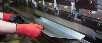
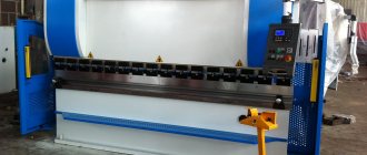
Manual sheet bending machines and mechanically driven machines are used to bend sheet material blanks. The principle of operation is that a workpiece is secured to the machine table with a clamp, which is positioned at the point of bending relative to the clamp. Then the rotary traverse is set in motion, rotates to the set angle and thereby bends the workpiece to the desired angle. The machine has equipment that allows you to bend various profiles.
Straightening is a metalworking operation intended to eliminate distortions in the shape of a workpiece (dents, bulging, waviness, warping, curvature, etc.) through plastic deformation. The metal is straightened both in cold and heated states. Straightening can be done by hand on a steel or cast iron plate or on an anvil. Machine straightening is carried out on presses and straightening rollers.For straightening the following are used: hammers made of soft materials (copper, lead, wood) with a round polished striker (a square striker leaves marks in the form of nicks); smoothers and supports (metal or wooden blocks) for straightening thin sheet and strip metal; correct headstocks for hardened parts with shaped surfaces.
The curvature of the workpieces is checked by eye using the gap between the plate and the workpiece laid on it. Bent areas are marked with chalk. The easiest way to straighten metal that is curved along a plane. In this case, strong blows are applied with a hammer or sledgehammer to the most convex places, reducing the force of the blow as they are straightened. In this case, the workpiece is periodically turned from one side to the other. It is more difficult to straighten metal that is bent along an edge. Here they resort to stretching part of the workpiece. It is recommended to straighten metal that has a twisted (spiral) bend using the unwinding method. To do this, one end of the workpiece is clamped with a bench vice, and the other with a hand vice. Then the curvature is straightened with a lever. The results of editing are checked by eye, and a more accurate check is carried out on a marking or control plate along the clearance.
Straightening sheet material is a complex operation.
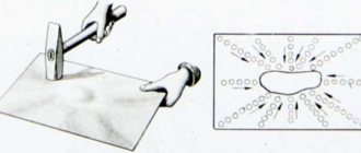
It depends on the type of deformation of the workpiece (bulge or dent in the middle of the sheet, waviness of the edges and edges, both convexity and waviness of the edges, etc.). The wavy areas on the workpiece are first outlined with chalk or a pencil, then it is placed on the slab with the convex side up so that the entire surface of the workpiece lies on the slab. Holding the sheet with your left hand in a mitten, with your right hand you strike with a hammer from the edge of the sheet towards the convexity (as shown by the arrows in 2.5a). As you approach the bulge, the blows should be weaker and more frequent. During straightening, the sheet is turned in a horizontal plane so that the blows are evenly distributed in a circle over the entire area of the workpiece. If there are several bulges, blows are applied in the interval between them, as a result of which the sheet is stretched and all the bulges are reduced into one, which is straightened in the manner indicated above. If the sheet has wavy edges but a smooth middle, then the blows are applied from the middle of the sheet to the edges. As a result, the sheet in the middle is stretched and the waves along its edges disappear. After this, the sheet is turned over and continued to be straightened in the same way until the required straightness and flatness tolerances are obtained. To straighten thin sheets, wooden mallets are used, and very thin sheets are ironed with wooden or metal smoothing bars. In this case, the sheets are periodically turned over. The quality of editing is controlled using a ruler.
Straightening (hardened workpieces is carried out with various hammers with a hardened striker or a special hammer with a rounded narrow side of the striker. The blows are applied not on the convex, but on the concave side of the workpiece. In this case, the metal fibers on the concave side are stretched and the workpiece is straightened. Straightening of workpieces of complex shape, for example, a square , in which the angle between the measuring sides has changed after hardening, is produced in the following ways: if the angle is less than 90°, then blows with a hammer are applied at the top of the inner corner, if more than 90°, at the top of the outer corner.
Bending is one of the most common metalworking operations. It is used to give the workpiece a curved shape along a given contour. In progress
When bending, metal is subjected to the simultaneous action of tensile and compressive stresses, therefore it is necessary to take into account the mechanical properties of the metal, its elasticity/degree of deformation, thickness, shape and cross-sectional dimensions of the workpiece, angles and bending radii of the part. The bending radius of the part should not be taken close to the minimum acceptable unless this is dictated by design requirements. It is advisable not to allow the bending radius to be less than the thickness of the workpiece, as this leads to the appearance of cracks and other defects. In a cold state, it is recommended to bend parts made of sheet steel with a thickness of up to 5 mm, of strip steel with a thickness of up to 7 mm, and of round steel with a diameter of up to 10 mm.
When bending strips of sheet steel, a bend mark is first applied to it. Then the workpiece is clamped in a vice between the square jaws so that the marking line faces the stationary jaw of the vice and protrudes 0.5 mm above it. Finally, with hammer blows directed towards the stationary jaw, the end of the strip is bent
To bend the staple, the workpiece is clamped in a vice between a square and a mandrel bar and the first end is bent. Then, having placed a mandrel bar of the required size inside the bracket, the bracket is clamped in a vice at the level of the marks and the second leg is bent.
Bending of a strip at an acute angle using a special mandrel is shown in 2.7, d.
Bending a clamp made of thin strip steel is performed in the following sequence: first, a mandrel of the required diameter is clamped in a vice. Then the workpiece is bent on the mandrel with two pliers and the clamp is finally processed using a hammer on the mandrel in a vice. The finishing of the half-open clamp is carried out on the stove.
In machine designs there are units with different directions and bending shapes of parts: a cotter pin or washer in a nut-bolt connection; bending of both parts being connected; one of the parts of the assembly is bent into the recess or hole of the other.
Bending work is also carried out in connection with the fitting of various pipes. In a cold state, copper and brass tubes of small diameter (up to 8
mm) with large radii of curvature (more than 10...12 diameters). The same tubes of larger diameter (8...14 mm) are bent manually using templates or spiral tightly wound springs, which are placed inside the pipe at the bend. Pipes with a diameter of more than 20 mm are bent, as a rule, using special devices or bending machines, after first filling the pipes with sand or molten rosin. Copper and brass pipes are annealed in the bending area before bending. Steel pipes with a diameter of up to 10 mm are bent without heating and without filler, and pipes of large diameters are bent in a hot state and, as a rule, with filler. Aluminum and duralumin pipes are bent when hot. Pipes are heated only in the bending zone
length approximately jgd, where a is the outer bending angle;
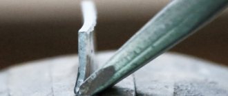
Chopping is a metal cutting operation. Using a cutting tool - a chisel, a crosspiece or a groover - an excess layer of metal is removed from the workpiece, it is cut into pieces, a hole is cut out, lubrication grooves are cut, etc. Cutting is carried out in cases where, due to production conditions, machine processing is impossible or when it is not possible high processing precision is required. Chopping of small workpieces is carried out in a vice, large workpieces are cut on a slab or anvil.
The following tools are used for chopping: chisel, crossmeisel, groovers.
The metalwork chisel consists of three parts: working 2, middle 3 and impact (strike) 4 (2.10, a). The wedge-shaped cutting edge of chisel 1 and the striker are hardened and tempered. After heat treatment, the hardness of the cutting edge reaches HRC356...61, the striker - HRC337...41. The chisel has a length of 100...200 mm, and the width of the cutting edge is 5...25 mm, respectively. The sharpening angle of the chisel, depending on the material being processed, should be:
Hard materials (cast iron, hard steel, bronze) 70°
Medium hard materials (steel) I…. 60°
Soft materials (copper, brass) 45°
Aluminum alloys and zinc 35°
The smaller the point angle, the less force must be applied to cut. However, the greater the hardness and brittleness of the metal being processed, the stronger the cutting edge should be and the larger the sharpening angle; The chisel head has the shape of a truncated cone with a semicircular upper base. Therefore, a blow delivered by a hammer always falls on its center.
The Kreutzmeisel differs from the chisel in having a narrower cutting edge (2.10, b). It is used for cutting out narrow grooves, grooves, etc. The sharpening angles, hardness of the working and impact parts of the cross-section are the same as those of a chisel.
Pointers (2.10, c) differ from cross-cutters in the curved shape of the cutting edge and are used for cutting out lubrication grooves in bearing shells and bushings and for other similar work.
Before work, the chisel is placed on the workbench on the left side of the vice with the cutting edge facing you, and the hammer is placed on the right side of the vice with the striker pointing towards the vice. When chopping, the correct position of the mechanic’s body is of great importance: at the vice, one must stand steadily and half-turn towards it.
The quality and productivity of cutting depends on the hammer blow. There are three types of hammer blows: wrist, elbow and shoulder. During a wrist strike, only the right hand bends. This blow is used when performing light and precise work: removing thin layers of metal, removing small irregularities, chopping thin sheet steel, etc. With an elbow blow, the arm bends at the elbow and the blow is stronger. This blow is used when removing a layer of metal of medium thickness, cutting grooves and grooves. During a shoulder strike, the hand moves in the shoulder, while
It turns out to be a big swing and maximum impact force. The shoulder blow is used when cutting thick metal, removing large allowances in one pass, and processing large surfaces. The frequency of hammer swings should be from 40 to 60 beats per minute for wrist blows and from 30 to 40 for elbow and shoulder blows. When chopping, the hammer is taken with the right hand by the handle on strip and sheet metal standing 15...30 mm from its end so that four fingers cover the handle, and the thumb is placed on the index finger. The chisel is held with the left hand, without squeezing the fingers tightly, at a distance of 20...30 mm from its head. 26
To protect your hand from an accidental blow with a hammer, it is advisable to put a rubber washer with a thickness of 8...10 mm and a diameter of 45...50 mm on the upper part of the chisel.
When cutting metal, the correct alignment of the chisel axis relative to the workpiece surface is of great importance. The angle between the workpiece (the planes of the jaws of the vice) and the axis of the chisel should be equal to 45°, the angle of inclination of the chisel depends on the sharpening angle of the cutting edge and should be 30...35°. At a smaller angle of inclination, the chisel slides rather than cuts; at a larger angle, it goes too deep into the metal, creating greater unevenness of the processed surface.
When chopping, your hands must act in concert. With your right hand you should accurately hit the chisel with a hammer, and with your left hand you should move the chisel along the metal. In this case, you need to look not at the head, but at the cutting edge of the chisel.
When cutting strip and sheet metal at the level of the jaws of the vice, the part of the workpiece that goes into the chips (cut down) should be located above the jaws, and the marking line should be exactly at their level without distortion.
The chopping is performed with an elbow strike. When placing marking marks above the level of the jaws, the angle between the axis of the chisel and the surface being processed is periodically reduced
When cutting down a layer of metal on a wide flat surface, the marking marks should protrude above the jaws of the vice by 5...10 mm. In this case, first, grooves with a width of 8 ... 10 mm are cut with a cross-section. The width of the spaces between the grooves should be 0.8 times the length of the cutting edge of the chisel. Then, the resulting protrusion is cut off with a chisel. The thickness of the chips removed by the crossmeisel in one stroke is 0.5...1 mm, and when cutting off the protrusions with a chisel, it is 1.5...2 mm. Cast iron, bronze and other brittle metals are cut without reaching the opposite edge of the workpiece. Uncut areas should be cut from the opposite side or first beveled at an angle of 45°.
When cutting out grooves and curved lubrication grooves (2.14.6), first marks are applied to the workpiece surface to be machined, then grooves 1.5...2 mm deep are cut with a cross-cut tool for each pass. The unevenness remaining after cutting is removed with a groover, giving the grooves the same width and depth along the entire length of the workpiece.
When cutting out a figured workpiece on a slab or anvil, first cut the marked outline with light blows, departing from the marks by 2...3 mm. The sheet is cut with strong blows to the chisel. If the sheet is sufficient
but thick, it is turned over and chopped from the opposite side along the outlined contour. When cutting out workpieces with curved contours, it is necessary to use a chisel with a rounded blade or a cross-cutting tool.
Various techniques for cutting metal are shown in 2.15.
Sharpening of chisels and crosspieces is carried out on sharpening (sharpening) machines. For sharpening tools made of tool steels (carbon, alloyed from electrocorundum with grain size 40, 50 or 63 on a ceramic bond. Before starting work, the tool rest of the sharpening machine is installed so that the gap between it and the periphery of the grinding wheel does not exceed 2...3 mm. Then the protective guard is lowered screen and turn on the machine. The chisel is set at an angle of 30...40° to the periphery of the circle and, with light pressure, slowly moved across the entire width of the circle. During operation, it should be periodically rotated first with one side or the other to ensure uniform and symmetrical sharpening. In this case the chisel is lowered into water each time for cooling. The side edges of the chisel after sharpening must be flat, the same in width and have the same angles of inclination. The sharpening angle is checked with a template on which there are angular cutouts of 70, 60, 45 and 35 ° (2.16, a, b) After sharpening, the burrs are removed with a fine-grained abrasive stone (the blade is threaded).
Cutting is the operation of dividing into parts round, strip, profile rolled products, as well as pipes, manually and mechanically. Manual cutting of workpieces, depending on the profile and cross-sectional area, is carried out using various tools: hacksaws, scissors
(manual, chair, lever), pipe cutters and gas-flame torches. It consists of a frame (hacksaw), a movable head, a screw with a nut for tensioning the hacksaw blade, and a fixed head with a shank and handle. Hacksaw frames are either solid or sliding.
A hacksaw blade is a thin and narrow steel plate with teeth on one edge. Each tooth of the hacksaw blade has the shape of a wedge (cutter), on which the rear
angle a, sharpening angle 8, rake angle v and cutting angle b,
A hand saw is the most common tool for cutting thick sheets of strip and profile metal, as well as for cutting grooves,
To reduce the friction of the hacksaw blade on the walls of the metal being cut (cut), its teeth are moved in different directions, thus increasing the thickness of the blade h to the width of the cut. Teeth with a large pitch are bent one at a time alternately to the right and left, teeth with a small pitch - two or three to the right and two or three to the left; a wavy line should form.
When cutting metal with a hacksaw, the mechanic’s body should be turned to the right at an angle of 45° to the axis of the vice. The position of the legs is shown in 2.17, f.
Before you start cutting metal, you need to choose a hacksaw blade based on the hardness, shape and size of the metal being cut. The degree of tension of the blade in the hacksaw frame is checked by lightly pressing your finger on the blade from the side: if it does not bend, then the tension is considered sufficient. When working, the end of the handle should rest against the middle of the palm of the right hand, and the thumb should lie along the handle on top. With your left hand, take the hacksaw frame so that your thumb is inside the frame, and the rest cover the tension screw of the movable head. The hacksaw is held in a horizontal position, moving smoothly, without jerking, and making from 30 to 60 double strokes per minute. When moving a hacksaw, at least 2/3 of its length should work. When cutting thin material with a hacksaw, it is clamped in a vice between two wooden blocks and cut together with them. Techniques for cutting metal are shown in 2.18.
Basic techniques for bending pipe parts
Bending of pipe parts is carried out in cold and hot states by manual and mechanized methods, with and without fillers.
Fillers are used to prevent the formation of folds and flattening of pipe walls. Dried fine sand or synthetic granules are used as fillers.
For each pipe, depending on its diameter and material, the minimum permissible bending radius is established. With a smaller radius, bending is unacceptable (Table 1).
Table 1. Values of the minimum permissible bending radii of pipes in a cold state, mm
| Pipe outer diameter, mm | Pipe material | Pipe outer diameter, mm | Pipe material | ||||||
| Steel 45 | Steel 35 | Steel 20 | Steel 10 | Steel 45 | Steel 35 | Steel 20 | Steel 10 | ||
| 18 | 74 | 62 | 56 | 43 | 105 | 450 | 344 | 282 | 240 |
| 24 | 95 | 79 | 65 | 55 | 110 | 510 | 377 | 310 | 264 |
| 32 | 115 | 96 | 79 | 67 | 130 | 536 | 450 | 370 | 315 |
| 38 | 156 | 131 | 107 | 91 | 145 | 578 | 484 | 398 | 339 |
| 50 | 197 | 165 | 136 | 115 | 155 | 620 | 522 | 430 | 360 |
| 60 | 238 | 199 | 165 | 139 | 181 | 720 | 600 | 498 | 425 |
| 75 | 280 | 260 | 194 | 173 | 194 | 752 | 630 | 516 | 444 |
| 80 | 324 | 270 | 224 | 190 | 206 | 835 | 702 | 575 | 488 |
| 90 | 362 | 302 | 250 | 213 | 220 | 920 | 770 | 635 | 540 |
When cold bending pipes with a diameter of up to 25 mm, hand tools are used.
In Fig. 4, a shows a manual machine designed for bending pipes with a diameter of 12 to 20 mm. The machine has an axis 1 and a base plate 2, with which it is bolted to the workbench. The working parts of the machine are a fixed roller 4 with a clamp 5, mounted on axis 1, and a movable roller 3, mounted on a bracket 6 with a handle 7. The end of the bent pipe is placed in the clamp between the rollers, then the bracket with the movable roller is rotated around the axis of the fixed roller until the required bend, after which the bracket is returned to its original position and the pipe is removed.
Rice. 4. Bending using hand tools
To bend copper tubes of different diameters when assembling machines, a multi-strand pipe bender (5.66, b) is used. In this case, the tube is passed between rollers 1 and 2 until it comes into contact with the stop, then when the fork 3 is turned, the movable roller 2 rolls around the stationary one, bending the tube along a radius equal to the radius of roller 1.
Using a manual lever pipe bender (5.66, c), you can bend steel gas pipes with a diameter of 1/2, 3/4 and 1" in a cold state without filler.
For manual bending of steel pipes with a diameter of up to 50 mm at an angle of 180° without filler in a cold state, a special head with a manual drive can be used.
Application areas of various types of metal bending
Different types of metal bending are used in small enterprises, as well as in everyday life, when the production of profiles of different sizes, prefabricated partitions, cabinet products, corners, channels, slopes, gutters, metal frames, suspended building systems, etc. is required.
Pipe bending is also carried out both on an industrial scale and at home. In some cases, the configuration of their connections can be complex. To reduce the number of elements and threaded connections used, the pipes are given a certain shape, for which they are bent at the desired angle. In this way, sewer, water and gas pipes of the desired configuration are obtained with minimal costs, while ensuring minimal resistance inside the networks.