Safety precautions
Before working with equipment, you must undergo a medical examination. Operational and safety training is also required. It includes the following rules:
- Do only the work that is assigned to you, and only in a safe manner.
- Work only on equipment in which you have special skills.
- Work only in a special uniform, which is issued before starting work.
- The employee must be provided with ample space to work.
- Before work, it is necessary to check the serviceability of the device.
- Under no circumstances should you attempt to repair the device yourself. Do not touch the internal mechanism of the machine
- There should be no unnecessary items in the workplace.
- The workpiece must be firmly fixed.
- Do not touch the material being processed.
- Do not touch workpieces during operation.
Spindle assembly
Spindle speed and feed rates are adjusted for control modes:
- Automatic - a command device that is configured in advance to perform the technological process. Its design allows you to give a control impulse to the electromagnetic clutches used to switch gears (located in the gearbox).
- Manual - using the toggle switches located on this box.
The spindle unit provides feeding/fastening of the rod using a hydraulic device using a collet.
Clamping/unfastening of bar stock is carried out automatically, piece workpiece is done manually. The part obtained from the bar is cut off, and the turret is returned to the starting position to adjust the length of the other part along the stop.
Electrical equipment
The electrical equipment of the 1516 is demonstrated with electric motors, controls and safety switches.
We dismantle the sewerage system in the apartment
Power supply circuit for the 1516 machine
To operate the machine and control it, currents with a wide variety of voltages are used. Thus, the voltage in the general power supply network is 380 V. The coils on magnetic starters use a voltage of 110 V electric current. The clutches located in the speed and feed boxes, as well as local lighting, are clearly 24 V. The step finder uses voltages of 36 and 90 V.
Description of the electrical circuit of the machine 1516. It is equipped with motors whose rotors are squirrel-cage and carry out: the main movement on the machine, the supply of tools, as well as the crossbar and lubrication system.
The electrical circuit for controlling the drives is provided in the photo. The control equipment is located in the niche of the frame. The machine is controlled using a remote control.
Wiring diagram of machine drives 1516
Some features of the machines
The units described above are characterized by a fairly high level of performance. If we compare them with the most primitive turning installations, this is explained by a number of factors.
- The use of fast devices for feeding and hardening of workpieces.
- Combinatorial operation of the turret and transverse support.
- Quickly change the device used in the work.
- The use of new holders, as well as various tools that differ in their combined appearance.
To ensure high performance and proper functioning, you need to configure it correctly. Proper setting refers to the selection of tools that are used in the work and their installation in holders, as well as the manufacture and installation of a longitudinal or transverse stop. The stop will be adjusted in the axial or radial direction.
On many turret machines, the frequency, as well as the feed and rotation, will be selected using a command device. Chuck units that were produced in Russia or even in the Soviet Union can work with workpieces with a cross-sectional size from 15 to 60 cm. Rod equipment is characterized by the following parameters: the distance through which the head can move is maximally large, the cross-section of the products is small.
Simple turret machines are used in many domestic enterprises. In recent years, you can notice a tendency to exchange them for the most advanced equipment, which has numerical control. CNC machines have many advantages, they are characterized by a high level of automation and operation, as well as good processing accuracy.
Copy
The 1341 turret lathe has mechanisms used for thread cutting and copying.
They use a thread cutting mechanism on a copier thread blank using a thread comb. This technology involves multiple passes to obtain a complete thread profile. The device is located in the gearbox housing. Its drive is driven by gears from the spindle.
Another copier has a copying ruler, which is used for longitudinal and transverse copying. In this case, conical and shaped surfaces are obtained. Shaped surfaces are obtained by installing a curved template instead of a carbon ruler.
In the longitudinal direction of copying, the support moves to the spindle assembly, and the turret rotates, repeating the profile of the copier.
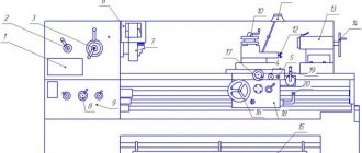
Basic elements of beds
The following is fixed to the main or lower frame:
- cast trough for coolant;
- auxiliary frame with guides for placing and moving the caliper;
- gearbox with spindle;
- gearbox;
- electrical cabinet;
- thread cutting device;
- copying device:
- container for oil used by the hydraulic drive;
- spindle and pump electric motors;
- box for collecting shavings.
General view of the turret lathe 1341
A carbon ruler is mounted on a bracket on the auxiliary frame. The folding stop is located on the right side of the caliper. It is designed to shut off the supply. Its transition to the working or neutral position is carried out using the handle.
Components of model 1341
On the 1341 turret lathe, parts are processed in automatic and semi-automatic modes. Semi-automatic mode is used when processing piece workpieces. They are secured manually with three chuck jaws. In automatic mode, a steel rod is used, fixed with a collet-type chuck. The rod is secured by a hydraulic device.
Kinematic diagram of turret lathe 1341
The most important components of the 1341 machine include:
- lower and auxiliary beds;
- boxes: speeds;
- innings;
Appearance of machine 1341
Topic 8.6 Control diagram of a turret lathe.
The drive of the main movement and feed movement of the turret lathe (Fig. 53) is carried out from the M1 electric motor with a power of 14 kW, the M2 electric motor (1.7 kW) drives the hydraulic system pump, and is also used to quickly move both supports of the machine. The M3 engine (0.125 kW) drives the coolant pump. The spindle speed is adjusted in steps by moving gears in the gearbox using hydraulic cylinders of the hydraulic system. The gearbox contains a clutch consisting of two clutch halves to enable right and left rotation of the spindle. These coupling halves connect the M1 engine shaft to the gearbox input shaft. These clutches are turned on and off by hydraulic cylinders, the spools of which are opened using electromagnets YA 1 and YA 2 (see Fig. 49, b). To quickly stop the spindle, an electro-hydraulic brake is installed in the gearbox, which is also controlled using a hydraulic cylinder and electromagnet YA 3.
When you press the SB2 “Start” button, power is supplied to the linear contactor KM and the motors M1, M2 and M3 begin to rotate. When the angular velocity of the motor M1 reaches the value ω = 0.25ωн, the contact of the centrifugal (mechanical) speed control relay RKS in the circuit of the intermediate relay coil KL3 closes, preparing the spindle quick stop circuit for switching on.
To obtain right rotation of the spindle from a stationary state, press the SB4 “Right” button. It triggers and becomes self-powered by relay KL4, with its contact supplying power to the coil of relay KL3, which also triggers. After releasing the SB4 button, the electromagnet coil YA1 receives power. The right half of the clutch is activated, connecting the spindle to the output shaft of the gearbox, and it rotates clockwise at the previously set speed.
To obtain left rotation of the spindle from a stationary state (counterclockwise), press the SB5 “Left” button. Relays KL5 and KL3 are activated, and after releasing the SB5 button, the electromagnet coil YA2 receives power through the closed contact KL5. The left half of the clutch is engaged and the spindle begins to rotate counterclockwise at the same speed.
To stop the right or left rotation of the spindle, press the SB3 “Stop” button. In this case, KL4, KL3 and YA1 or KL5, KL3 and YA2 lose power. As a result, the reversible clutch spool is set to the middle position, there is no pressure on the hydraulic cylinder pistons and the clutch disconnects the spindle from the gearbox.
To change the set spindle rotation speed (without turning off the engine and while the spindle is rotating), you must first set the new speed on the gearbox using the appropriate handle. After pressing the SB6 “Switch” button the intermediate relay KL2 is triggered and becomes self-powered, which with its contacts supplies power to the coil of the time relay CT. At the same time, the break contact KL2 breaks the power supply circuit of YA1 (or YA2), and the make contact KL2 supplies power to YA3 (contact KL3 is already closed). One of the clutches (right or left) is disconnected, the spindle is disconnected from the gearbox and stopped by a hydraulic brake. After this, the hydraulic cylinders in the gearbox switch the gears to a new speed. By the time this switching is completed (0.5-1 second), the KT time relay contact in the KL2 coil circuit opens. KL2 and YA3 are turned off, and YA1 (or YA2) is turned on again. The spindle is reconnected to the gearbox, rotating in the same direction, but at a new speed. If the spindle speed is switched when the M1 motor is turned off, and also if M1 did not have time to accelerate to a speed of 0.25 (the PKS contact is not closed), then when SB6 is pressed, YA3 and CT are not turned on, since spindle braking is not required.
Protection against short-circuit currents and long-term overloads is provided by fuses FU1÷FU4 and electrothermal relays KK1, KK2 and KK3.
For safety reasons, the control circuit is powered from a reduced voltage of 127 V, the local lighting lamp EL is powered by a voltage of 36 V, and the signal lamps HL1 and HL2 are powered by a voltage of 5 V from the secondary windings of transformer T.
Practical work No. 9.
Settings
The machine is set up by starting a series of identical parts. It provides:
- development: part manufacturing technology;
- setup cards;
- spindle speed;
https://youtube.com/watch?v=_yb2NaWntls
Technical features of installations
Lathe units of this group also have some additional equipment - faceplates, three or four-jaw chucks. The latter operate thanks to a built-in drive, which can be manual or hydraulic. This allows processing of large workpieces. Most often, such parts can be obtained using casting, forging or stamping.
Some technical features have turret-type units, which are designed to work with rod elements. They are equipped with a spindle with a small hole. Also, these units have a special mechanism that ensures feeding and subsequent fixation of the workpiece in the desired position. If such machines are equipped with a suitable chuck, they are suitable for processing other parts that are produced by casting, stamping or forging.
The location of the axis about which the working head of the device rotates affects the number of supports. If it is horizontal, then an element is installed that is capable of only circular and longitudinal movements.
When the axis is placed vertically or at an angle, then two supports can be mounted on it - revolving and transverse. Two tool holders can be installed on the last element of the machine. They ensure the simultaneous presence of up to six working tools, which is very convenient during operation of the equipment.
Tool holder
Multi-spindle machines
This equipment is divided into two types:
- parallel action;
- sequential action.
The camshaft is a characteristic part in semi-automatic and automatic lathes. Cams of various shapes and designs are mounted on it (depending on the purpose). They control all auxiliary and working movements of machine tools through a system of mechanical and other connections.
The most commonly used cam designs are:
- drums They are designed to control auxiliary and working movements of machine tools. It is a cylinder that is equipped with overhead cams or shaped milled grooves;
- disk. They are needed to set the working parts of semi-automatic and automatic machines in motion - calipers and turrets.
Discs with end-mounted cams are used only to activate auxiliary movements (rotation of the turret, clamping and movement of the rod, etc.). The discs have a separate scale. Most often it is divided into hundredths of revolutions. This scale is necessary to install the cams in the right place.
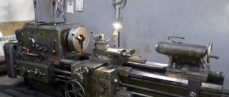
Turret lathes
Turret lathes differ from screw-cutting lathes in that they do not have a tailstock and a lead screw, and a rotary multi-position turret head is installed on the longitudinal support, in the sockets of which various cutting tools are installed, and when using special combined holders in one Several cutting tools are installed in the turret socket. Each cutting tool, when turning the head, sequentially processes the part. Turret heads are prismatic and cylindrical.
Turret lathes are recommended for use in mass production when the size of parts in a batch is at least 10 - 20 pieces.
| General view of a turret lathe. |
Turret lathes differ from conventional lathes in that work on them can be carried out by a set of cutting tools of several types installed in a certain sequence in the turret and on the transverse support.
Turret lathes differ from conventional lathes in that work on them can be carried out by a set of cutting tools installed in a certain sequence in the turret and on the transverse support. Therefore, turret lathes are more productive than conventional lathes and, as a rule, are used in mass production.
In some cases, turret lathes allow the use of special devices to automate the processing cycle, including loading workpieces and removing them from the machine after processing.
| The layout of the working bodies, installed at an angle when reproducing the screw guide -. line. |
Turret lathes (Fig. 1.48) have a layout characteristic of conventional lathes.
| General view of the turret lathe model Shch365. |
Turret lathes are designed for processing parts of complex shapes in mass production, including... The processing process on these machines consists of several sequential operations, during which various tools are used: cutters, drills, taps, etc., mounted in a so-called turret, which is mounted on a support. In electrical engineering, turret lathes are used to process bearing shields, bushings and pressure cones of electrical machine commutators. The use of these machines increases labor productivity by 2–3 times compared to processing on screw-cutting lathes.
Turret lathes are designed for processing workpieces of complex shape (stepped, etc.), which in some cases have a central hole. To produce such parts, it is necessary to consistently use a variety of cutting tools.
Turret lathes are designed for processing workpieces of complex shapes (stepped, etc.) and especially workpieces that have a stepped central hole. To produce such parts, it is necessary to consistently use a variety of cutting tools.
Turret lathes are used in serial and large-scale production when using a group method of processing parts, when parts of similar shape can be processed using the same technological process on the same machine and fixture with minor readjustments.
| Schemes for processing shaped surfaces. |
Turret lathes are designed for processing parts from rods or piece workpieces. They can perform almost all types of turning work. Parts to be processed on turret lathes have several machined surfaces, which determines the need for multi-tool setup. The turret head allows such adjustment, as it has several slots for attaching tool holders. The holder, in turn, can also accommodate several tools. The combination of a transverse slide with a turret makes it possible to process several surfaces of a part at the same time. Multi-tool setup of machines requires a significant amount of time, so turret lathes are used in mass production.
Principle of operation
In mass production, the rod is mounted in a collet chuck using hydraulics. There is a built-in mechanism that ensures that the workpiece is fed to the required length. When working with piece workpieces, the turner secures them manually.
Typically, machines are equipped with a universal collet with replaceable jaws for clamping a circle and a polyhedron. The kit includes additional mandrels, bushings and other accessories.
Important!
On some models, it is possible to replace the collet with a three-jaw chuck.
Modifications of machines for chuck work are designed for processing cast, stamped and forged piece workpieces. They are equipped with three-jaw (or four-jaw) chucks.
All tools are mounted in the turret. Having completed the working stroke with one cutter (drill, reamer), it changes position and feeds a new tool. The length of the tool's working stroke is limited by special stops that shut off the feed.
Spindle assembly
Spindle speed and feed rates are adjusted for control modes:
- Automatic - a command device that is configured in advance to perform the technological process. Its design allows you to give a control impulse to the electromagnetic clutches used to switch gears (located in the gearbox).
- Manual - using the toggle switches located on this box.
The spindle unit provides feeding/fastening of the rod using a hydraulic device using a collet.
Clamping/unfastening of bar stock is carried out automatically, piece workpiece is done manually. The part obtained from the bar is cut off, and the turret is returned to the starting position to adjust the length of the other part along the stop.
Caliper
The caliper moves along the guides of the auxiliary frame using a rack and pinion.
The support contains:
- turret;
- command apparatus;
- stop drum;
- apron.
The head is attached to a shaft located on the caliper. The shaft rotates on ball bearings. The tool is secured into the head holes using holders. The holders provide rigidity of fastening, accuracy of installation and adjustment of the tool.
The same shaft is used to attach the command device and the stop drum. The head rotates after each working stroke, feeding the next tool to the processing zone. The command device ensures automatic activation of the required spindle speed and feed values corresponding to this type of tool.
Behind the command device there is a stop drum, which ensures automatic stop of the caliper when the required amount of tool movement is reached. The feed is switched off by cams installed in the grooves of the drum when they reach the folding stop.
Main design features
A universal screw-cutting lathe consists of main structural units, which are standard elements. These include:
- caliper;
- bed;
- thrust and spindle headstock;
- electrical equipment;
- drive shaft;
- guitar gears;
- a box that provides selection and change of feeds;
- lead screw - it is this detail that distinguishes a screw-cutting lathe from a standard lathe.
Depending on some features, the accuracy of the machine may vary. Therefore, universal equipment can be of both accuracy class N and increased – P.
Front and rear stock
The headstock or spindle has the main role of fixing the workpiece in processing and transmitting rotation to the workpiece from the electric motor.
The spindle is located inside the body of the headstock. A speed control handle is mounted on the outside of the machine body. The tailstock or thrust is necessary to fix the workpiece.
Caliper
The support is designed to move the tool holder with the cutter in the longitudinal, transverse direction relative to the axis of the machine. The lower part of the support is called the slide or carriage.
After a certain time of operation of the machine, the support will need to be adjusted, since otherwise the processing speed will decrease. Adjustment for gaps consists of tightening the wedge strip.
Compared to other parts, the caliper is large. The choice of tool holder is determined by the class of the machine. For large equipment, be sure to secure the cutters with an additional four screws.
Gearbox
This is the main part of the spindle drive. It transmits engine energy to the rest of the machine. Another function is to change the spindle speed and the operating speed of the entire machine.
The box is built into the spindle head housing or in a separate housing block. The speed can be changed in a stepless or stepwise manner. The standard gearbox includes the following components:
- gear system;
- V-belt transmission;
- reversible electric motor;
- electromagnetic clutch with braking system;
- handle for changing gears.
The gearbox operates using gears.
Spindle
This is the main part of the machine, which is made in the form of a shaft with a conical hole for securing workpieces. To ensure that the part has high strength and durability, it is made of high-strength steel.
In the classic version, the spindle is made on high-precision rolling bearings. A special ring is installed on the support of the part, which ensures the accuracy of the machine.
There is a conical hole at the end of the structure. The spindle needs a cavity to install a rod that helps, if necessary, knock the center out of the seat.
The strength and durability of the spindle directly depends on the bearings available there.
bed
This is the main part of the machine, which is made using cast iron. All the most important parts and elements of this design are attached to it.
The frame itself consists of two steel beams. The beams, in turn, are connected to each other by stiffening ribs. Each beam has a connection to two guides.
The guides on both sides belong to the prismatic group. The flat-shaped guide is located inside on the left side.
Threading
There are several ways to cut threads using a screw-cutting lathe. For this, a die, tap, cutter and other types of tools are used.
With their help it is possible to cut internal and external threads
When using a cutter, it is important to fully comply with the technology. It includes:
- correct sharpening of the cutter;
- accurate adjustment of machine operating modes;
- using a template, correct installation of the cutter in the center of the part;
- measuring the resulting dimensions using gauges or templates.
In such work, defects in the form of sharp points, torn threads, scuffing and crushing are unacceptable.
Electrical control unit
The standard control unit for a screw-cutting lathe includes several handles and buttons:
- handle for setting the number of revolutions;
- control system for setting cutting surface parameters;
- handles for caliper control.
A CNC machine has a more complex structure, but can work without operator participation at intermediate stages.
Apron
In the apron of a screw-cutting lathe there are mechanisms that convert the rotational movement of the lead screw and the lead shaft into the translational movement of the caliper.
Technical characteristics of the machine 1P420PF40
| Parameter name | 1P426DF3 | 1P420PF40 |
| Basic machine parameters | ||
| The largest diameter of the workpiece above the bed, mm | 500 | 450 |
| Largest diameter of the workpiece, mm | 250 | 200 |
| Maximum length of the workpiece, mm | 130 | |
| Diameter of clamping chucks, mm | 250; 315 | 200 |
| The largest diameter of the processed rod, mm | 65 | 50 |
| Spindle hole diameter, mm | 92 | 70 |
| Distance from the end of the spindle to the edge of the turret, mm | 350..850 | – |
| Distance from the spindle axis to the base of the machine, mm | 1120 | |
| The largest size of threads cut with dies and taps, mm | ||
| Number of tools in turret | 12 | |
| Largest cross-section of cutters in the turret head, mm | 25 x 25 | |
| Diameter of the hole in the turret for a cylindrical shank, mm | 40 | |
| Spindle | ||
| Limits of spindle speed with chuck, rpm | 30..1800 | 20..4000 |
| Limits of the speed of the driven tool, rpm | – | 20..2500;20..1500 |
| Number of spindle speeds, rpm | 18 | B/s |
| The end of the spindle is flanged according to GOST 12595-72 | 8 | 6 |
| Maximum permissible torque on the spindle, not less than, Nm (kg*m) | 500 | |
| Maximum permissible torque on the tool spindle, not less than, Nm (kg*m) | – | 10 |
| Caliper. Submissions | ||
| Maximum movement of the turret support: longitudinal (Z) / transverse (X), mm | 560/ 340 | 630/ 240 |
| Speed range of longitudinal feeds of the turret caliper (Z), mm/min | 1..6000 | 1..5000 |
| Speed range of transverse feeds of the turret support (X), mm/min | 0,5..3000 | 1..5000 |
| Speed of fast movements of the caliper along the Z/X axis, m/min | 15 | 10 |
| Speed range of spindle circular feeds (C axis), deg/min | – | 1..2000 |
| Maximum feed force of the turret support along the Z/X axis, kN | 20/ 10 | |
| Turning time of the round turret head, s | 2 | |
| Hexagonal turret rotation time, s | 3 | – |
| The amount of movement of the turret caliper along the Z/X axis per pulse, mm | 0,010/ 0,005 | 0,001/ 0,0005 |
| Discreteness of setting the circular movement of the spindle, degrees | – | 0,001 |
| Number of tools in turret | 8; 6 | 12 |
| The largest diameter of the driven tool, mm | – | 12 |
| Caliper positioning accuracy in the longitudinal direction (Z axis), mm | 0,025 | |
| Caliper positioning accuracy in the transverse direction (X-axis), mm | 0,010 | |
| Spindle positioning accuracy (C axis), min | – | 2 |
| Maximum movement of the quill, mm | 180 | |
| Electrical equipment of the machine | ||
| Number of electric motors on the machine (with electric pumps), kW | 6 | 12 |
| Main drive electric motor, kW | 18,5 | 30/ 22 |
| Electric motor for longitudinal feed drive (Z axis), N*m | 13 | 13/13 |
| Cross feed drive electric motor (X axis), N*m | 13 | 10/13 |
| Circular feed drive electric motor (C axis), N*m | – | 10/13 |
| Drive tool electric motor, N*m | – | 10/13 |
| Electric motor drive of the gearbox lubrication system, kW | 0,55 | |
| Hydraulic pump electric motor, kW | 2,2 | 2,2 |
| Hydraulic station fan electric motor, kW | – | 0,12 |
| Cooling pump electric motor, kW | 0,12 | 2 x 0.12 |
| Main propulsion engine cooling electric motor, kW | – | 0,25 |
| Electric motor for fencing screen drive, kW | – | 0,18 |
| Electric drive motor for chip conveyor, kW | – | 0,55 |
| Total power of all electric motors, kW | 40,54/ 33,54 | |
| Dimensions and weight of the machine | ||
| Overall dimensions of the machine (length, width, height), mm | 3525 x 1570 x 2655 | 3470 x 2260 x 2300 |
| Machine weight, kg | 8660 | 5900 |