The method of ultrasonic flaw detection of welds has been used since 1930. Since then, various methods of echolocation have been developed. They reveal a violation of the integrity of the diffuse layer, the correspondence of the surfacing to the base metal in chemical composition, slag inclusions and oxide impurities are identified. The ultrasound (ultrasound diagnostic) procedure is comparable in accuracy to X-rays and radar. The device detects the smallest defects that reduce the strength of joints.
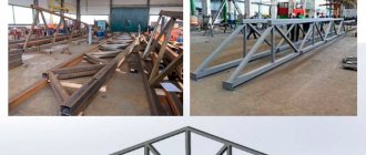
Among the non-destructive methods of seam inspection, ultrasonic has become the most accessible and effective, and has been put on stream. The results of checking the welder’s work are recorded in a special journal. The scope of application of ultrasonic testing of welded joints is limited only by the geometric parameters of the parts being welded. They diagnose the seams of pipelines, high-pressure vessels, and metal structures under heavy load.
What is ultrasonic testing of welding joints
Ultrasonic testing (UT) or ultrasonic flaw detection is a non-destructive testing method. Parts and materials exposed to it are not damaged. It is used in many areas and sectors in industry, medicine, etc.
This method is actively used in the inspection of welds such as butt, corner, overlap and T-joints with structural penetration (these are those seams in which, after welding, there will be no unwelded area left inside). The figure shows, as an example, a T-weld with structural penetration T8 according to GOST 5264)
The technique is based on the use of ultrasound (a sound wave with a frequency above the hearing threshold of more than 20 kHz; frequencies from 180 kHz - 10 MHz, and sometimes up to 100 MHz, are used for control).
Ultrasound testing uses 2 basic principles:
- Change in amplitude of the reflected signal (defects are detected).
- Measuring the time it takes a wave to travel through a product (thickness is determined)
Based on these 2 principles, inspection of welded joints, metal during incoming inspection, and various equipment that has been in use for a long time is carried out and its residual life needs to be assessed.
Ultrasound testing services from the TPE Atom laboratory
If organizations, due to the incompetence of management or in order to save money, do not attract specialists to carry out ultrasonic testing or other types of inspection (RK, VIC, steeloscopy) of structures and elements before putting them into operation, then this is fraught with additional costs and even emergency situations and man-made disasters . Therefore, it is so important to subject welded joints to non-destructive testing, including RK or ultrasonic testing, which is carried out using an ultrasonic flaw detector, thickness gauge and transducers. The echo signal, which is emitted by the piezoelectric transducer (PET) of ultrasound, is reflected from the inhomogeneity, discontinuity or interface of the media, and after returning to the PET is displayed on the screen of the flaw detector. Research is carried out twice or three times, and if the signal is not false, then an entry is made in the log book. Upon completion of the work, the product is handed over with an inspection certificate. Prices on the link
Employees of the TPE Atom laboratory carry out ultrasonic testing in accordance with special GOSTs and SPs, which regulate the methodology for carrying out this method of flaw detection. We provide a full range of services for ultrasonic diagnostics of welded joints; we check welded metal of various designs for various defects. The main advantages of ultrasonic inspection are that information about the condition of the connection is quickly obtained, various hidden defects are detected, and the cost of flaw detection is low. The price of ultrasonic testing is determined taking into account the dimensions and geometry of the object, and the number of welded elements being inspected. Our specialists will perform all the necessary work efficiently, quickly and in accordance with the requirements of regulatory documentation.
Why is ultrasound testing performed?
With this non-destructive testing method it is possible to:
- Assess the size of corrosion areas;
- Identify internal (subsurface) defects - cracks, lack of fusion, metal delamination, pores, slag inclusions and other non-continuity of the weld and base metal.
- Assess the quality of the seam and determine the depth of the defects.
This method diagnoses equipment, both existing and new (before commissioning), and also monitors the quality of welding after it has been completed.
When performing control, in some cases it is not even necessary to empty vessels and pipelines (removing the medium), which makes this technique very popular.
Equipment used
The following equipment is used for ultrasonic testing:
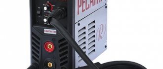
- Flaw detector.
- Piezoelectronic transducer (PET).
- Lemo connecting cable.
The flaw detectors currently used are small in size, convenient to use and not difficult to carry. Depending on the manufacturer, the functionality of flaw detectors varies from the simplest with monochrome displays such as UD-2-70 to the most compact and advanced with color displays and program control.
Piezoelectronic transducers (or PETs for short) differ in frequencies, input angles, radiation methods, and so on.
The following types are used to control welds:
- straight and inclined;
- combined and separate-combined;
- focusing, non-focusing, as well as chordates;
- contact and non-contact.
Combined transducers - have only one piezoelectric element which is both an emitter and a receiver at the same time.
Separately combined converters already have 2 piezoelements, one of which is a source of waves, and the other a receiver. These converters provide more accurate defect detection. They can be used to monitor surface defects and control surfaces with high roughness.
Design and principle of operation of an ultrasonic flaw detector
All devices have a generator, an ultrasound emitter and receiver, and a signal amplifier. The devices differ according to the type of generator. Piezoelements are most often used. The ultrasonic sensor sends signals pulsed, with pauses of up to five microseconds. The duration is adjusted depending on the density of the metal and the structural features of the defects being sought. Based on the reflection, a qualitative and quantitative assessment is made: a defect, the depth of its formation, and dimensions are identified.
The emitter is located in a movable probe; it moves along and across the seams being examined.
The diagnostic accuracy depends on the sensitivity of the receiver that detects the transmitted or reflected wave. At the boundary of the media, the wave changes direction; the operator must take this into account. It is easier to determine shadow areas - places where the wave is reflected. The sound signal is converted into an electrical signal, and the image is displayed on an oscilloscope. A reflected wave shows a peak, a constant wave shows a straight line.
Essence of the method
Echo method (in some sources – echo-pulse). This is the most commonly used ultrasonic testing method and is most often used to inspect welds. The principle of the method is as follows: a sound wave passing through the controlled product is reflected from the surface of the defect (if there is one) or from the surface of the bottom (if there are no defects). If a defect is detected, the device records this with a signal on the display. To use this method, access from only one side is sufficient and in some cases there is no need to disassemble the equipment.
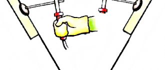
You can control welds without removing the reinforcement using inclined probes. To carry out the control, it will be necessary to clean the seam to a distance of 100 mm in both directions; the roughness should not exceed Ra 3.2. You will also need to apply a coupling fluid (gel, glycerin, mineral oil, etc.)
Echo-mirror method . To implement it, 2 probes are used, one is a transmitter that emits sound waves. The second is a receiver, a receiver of reflected waves from a defect or bottom surface. They are located on one side of the controlled part and move together.
This method is used to identify vertically located defects, most often lack of penetration, lack of fusion and cracks located at the root of the weld.
Delta method. The principle of the method is as follows: the emitter introduces sound waves into the product, which are scattered and transformed at the edges of the defect into a longitudinal wave, which is recorded by a longitudinal wave receiver. One-sided access is sufficient for control. This method is difficult to use due to the need for extremely precise adjustment of the flaw detector. There are also high demands on the competence of the flaw detector. This method is actively used where the presence of vertically oriented defects is expected.
The mirror shadow method is based on measuring the reduction in signal strength from a defect. During testing, the signal passes through the cross section of the object twice.
This method is often used in conjunction with the echo method for additional control.
Shadow (in some literature amplitude-shadow) - this method is based on reducing the amplitude of the sound wave after passing through the defect. It requires two-way access. The emitter is installed on one side, and the receiver on the other, and sound is performed. An important feature is that it is impossible to determine the depth of the defect. It is used to control sheet structures.
The reverb-through method is used for inspection in polymers, multilayer materials and composites. The sensors are located on one side of the test object; the sound wave transmitted through the body of the object makes several reflections from the bottom surfaces.
Acoustic emission method. This method is used where it is necessary to identify defects at an early stage of their formation. The method is based on the ability to study low-frequency sound waves during the occurrence of defects such as cracks and structural changes.
Many sensors are installed on the controlled products, which record these waves and transmit them to amplifiers. Next, the signal enters the information processing unit, in which extraneous noise is filtered out. The resulting value is displayed.
Below is a diagram of acoustic emission testing.
This method is most often used at chemical and petrochemical industry facilities: tanks, containers and pipelines.
Properties of ultrasonic wave
A sound wave as a type of mechanical vibration has the following properties:
- Period—(T) is the time during which one complete oscillation occurs.
- Wavelength – (λ) is the distance a wave travels in one oscillation.
- Purity (f) is an important characteristic that shows how many oscillations occur in 1 second.
- Amplitude (dB) – the maximum deviation of the wave from the equilibrium state.
Ultrasonic testing also takes into account the type of waves:
- longitudinal wave (tension/compression)
- transverse (shear)
- surface (Rayleigh wave)
- Head wave
- Lamb wave (in plates)
- Porchhammer waves (in rods)
Direction angles
When carrying out ultrasonic testing, PETs (piezoelectronic transducers) are used. They, in turn, differ in the angle of wave input into the controlled materials by:
- Direct.
- Inclined.
Direct —create and receive ultrasonic waves at right angles to the testing surface.
Oblique transducers - create and receive ultrasonic waves at various angles different from the normal to the surface. Most often in practice, probes are used with insertion angles of 50, 65 and 70 degrees.
What defects can be identified
During inspection, the following defects can be identified:
- Pores.
- Bundles.
- Slag and other inclusions.
- Lack of penetration.
- Lack of fusion of edges.
Only the main defects are listed. Using ultrasound, you can identify other discontinuities, as well as their location and size.
Application area – where ultrasonic testing is used
Ultrasonic testing is a very universal method and has a very wide range of applications. With its help, you can control both metal and non-metal products such as ceramics, polymers, glass. The only limitation is the control of porous materials in which strong wave attenuation occurs. It is also very difficult to use this method when inspecting products with complex configurations (threaded connections) and when inspecting small thicknesses.
Ultrasonic flaw detection (ultrasonic flaw detection) is used to control welds and base metal during technical diagnostics, construction, reconstruction during operation and installation. Used on such objects as:
- boiler inspection facilities (boiler equipment);
- lifting structures (cranes, hoists, elevators, etc.);
- gas supply facilities;
- mining industry (building and construction, as well as equipment of mines and mines);
- coal industry;
- control objects of the oil and gas industry;
- metallurgical industry;
- chemical and petrochemical industry facilities;
- railway transport;
- grain storage and processing;
- construction objects (buildings and structures, as well as metal structures);
- electric power industry.
What does the ultrasonic testing method reveal?
Ultrasonic testing, like RK, is used to test welded joints made of various metals and alloys, including austenitic steel. Diagnostic equipment specially designed for ultrasonic testing reveals:
- lack of penetration;
- cracks
- pores;
- delamination in the deposited metal;
- slag inclusions;
- foreign inclusions.
With the help of ultrasonic testing, TPE Atom LLC specialists working in Moscow and traveling to the region check the compliance of workpieces and products with the provisions of technical specifications, GOST, design documentation, evaluate the quality of various welded joints and various materials, detect internal defects, determine the size of defects, identify heterogeneity of the structure of materials and areas of corrosion damage.
We actively use ultrasonic testing in construction, mechanical engineering, energy, chemical and oil and gas industries, at enterprises that have high-pressure pipelines, and in individual cases during the reconstruction of buildings and premises.
Advantages and disadvantages of the technique
The advantages of the method are:
- Speed of inspection - data is obtained without delays in real time (no development of films or decoding of data from magnetic tapes is required).
- The high versatility of the method allows you to control a large range of materials and products.
- It is possible to perform control in all spatial positions.
- Automation of the method is possible.
- Control of large thicknesses (up to 3–5 m).
- The method is harmless to humans.
- Most equipment is compact and portable (facilitates work in the field).
Just like a coin has 2 sides, this method also has its 2nd side – disadvantages.
The disadvantages of the method include:
- It is difficult to estimate the actual size of the defect.
- A number of limitations when testing materials that have a granular or coarse-grained structure in which strong wave attenuation occurs.
- There is a dead zone when inspecting surface and subsurface defects.
- High quality surface cleaning is required when testing by contact methods.
Procedure for carrying out ultrasonic testing
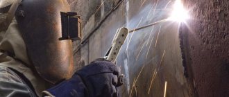
Let us consider the procedure for carrying out ultrasonic flaw detection using the example of weld inspection. Before inspection, all work on this equipment must be completed.
Before starting, it is necessary to clean the area along the weld seam to a distance D, which is calculated by the formula D = Lmax + 30 mm; where L is the length of the probe’s movement zone (usually 120 – 150 mm).
Cleaning for rental does not need to be done, but only metal splashes and corrosion with a depth of more than 1 mm can be removed. All nicks, dents and irregularities must be removed. Cleaning is carried out using metal brushes, files, and also using a grinding machine using abrasive wheels.
The roughness of the prepared surface should not be higher than Rz40 and the temperature at which the control will be carried out should be in the range from minus 30 to plus 30 degrees.
Next, to create acoustic contact, a contact fluid (glycerin, mineral transmission and machine oils, specialized fluids and gels) is applied to the surface.
Afterwards, the flaw detector is adjusted on standard samples SO-2 and SO-3, and the sensitivity is set using an artificially made reflector (defect) on a standard enterprise sample - SOP. The designs of SOPs with artificial reflectors are given below.
Standard sample (SOP) with a notch, this is used for setting up a flaw detector with a combined probe
SOP “punt” – in which a hole with a flat bottom is made for adjusting a chord-type probe.
The serviceability of PEPs is checked using standard samples of the enterprise SO-2 and SO-3. CO-3 is used to determine the exit point and boom.
Using CO-2, the insertion angle is determined.
The enterprise standard sample (SOP) shows the maximum permissible defect for a given test object at a given thickness. It is used to adjust the sensitivity of the flaw detector. First, the signal received by a single reflected beam is adjusted, and then the signal received during control by a direct beam is adjusted. The most commonly used methods of control are direct and single-reflected beams.
Next, the object itself is sounded. The transducer is placed perpendicular to the weld seam and smoothly moved, moving away and bringing it closer, making a kind of reciprocating movement. In the process of making movements, the transducer is turned at an angle from 10 to 15 degrees to the right to the left. The movement step should be no more than 5-6 mm.
During the scanning process, the flaw detector monitors the received signals on the display of the flaw detector and, in case of defects, marks the location on the product with a marker or chalk.
Below you can see the sound diagrams for various welding joints.
Results Evaluation Options
Interpretation of the results obtained by ultrasonic testing methods when sounding welded joints is one of the important stages of the work.
When a defect is detected, measure:
- The depth of the defect.
- Length.
- Distance between defects (if there are several of them).
- Maximum amplitude from the signal.
- Total length of defects.
The results are recorded in the control log, as well as in the conclusion or protocol. The control log indicates:
- The number of the welding joint according to the form and its type;
- length of the controlled area;
- SOP No.;
- operating frequency and input angle;
- control results;
- areas that could not be controlled (in the absence of access);
- date of inspection and signature of flaw detectors.
Defects detected during inspection are described using alphanumeric designations. To indicate defects, GOST 14782 should be used.
Ultrasonic inspection of welds
The testing technology is regulated by GOST R 55724-2013. Controller operators are issued certificates. Before the test, they are given instructions on TB. You have to check connections located in hard-to-reach places. The device must be grounded. The results are assessed according to several criteria. The following data is entered into the ultrasonic quality control log:
- length of the controlled weld;
- description of the defect (width, height, shape);
- transmitted wave range.
For diagnostics, the area under study (the roller plus the area of thermal influence) is cleaned. For better ultrasound penetration, an oily film is created on the surface. The device is set up according to the standard. The search for a reflected or transmitted signal takes place at maximum amplitude. Depending on the importance of the connection, inspection is carried out in one or two passes.
Training and certification of specialists
Ultrasonic flaw detection specialists are trained and certified in special certified organizations. There are 3 levels of qualification for flaw detectors.
Level I is assigned to beginners whose work will be carried out under the supervision of a specialist with level II or III. A first-level specialist cannot independently choose a control method, evaluate the results, or select technology and mode.
Level II flaw detectorists can independently carry out and supervise the work. Make a decision on the choice of control method, methods, technologies, and also evaluate the control results. They can develop technological maps and approve them.
Level III flaw detectors can supervise the work of level I and II flaw detectors, conduct training and certification.
Ultrasonic inspection of pipeline welds
Often, ultrasonic inspection of pipeline welds is carried out only on one side. In this case, inclined and straight probes are used. Depending on the wall thickness, PEPs are selected according to frequency.
The table below shows the criteria for selecting a converter.
If pipelines with a diameter from 10 to 530 mm with a small wall thickness (up to 8-9 mm) are monitored, it is better to use chordal separate-combined transducers. This will increase the speed of control and the accuracy of the results obtained.
The criteria for selecting a converter depending on the pipeline diameter and wall thickness are given in the table below.
Scope and possibilities of application of the ultrasonic testing technique
The test is carried out on connections of non-ferrous metals, cast iron, carbon and alloy steel. Using diagnostics of ultrasonic testing of welded seams, the following is revealed:
- porosity associated with the saturation of the melt with atmospheric gases;
- rust inclusions;
- lack of penetration;
- areas with a violation of the geometry of the part;
- cracks in the thermal influence zone;
- discontinuities of various nature;
- foreign inclusions in the melt;
- structural delaminations;
- heterogeneity of the deposited layer;
- folds of surfacing material;
- fistulas (through defects);
- sagging of the diffusion layer outside the joint.
Various structural elements are subjected to ultrasonic testing of welded joints:
- tee seams;
- pipe and flange ring connections;
- joints of any configuration, including complex shapes;
- longitudinal and transverse seams subjected to multidirectional loads or experiencing high pressure.