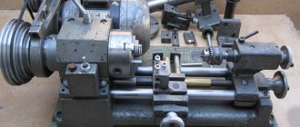
Many industries or workshops are faced with the need to produce metal parts in the form of bodies of revolution. At the same time, purchasing an industrial screw-cutting lathe, even a used one, turns out to be unprofitable.
A reasonable solution is to purchase benchtop lathe equipment of a well-proven model.
This performance is characterized by the following qualities:
- Low cost, affordable even for private workshops, the so-called “hobby” category.
- Full performance of all basic operations. The issue of limitation lies in the size and ability to perform the most complex turning, which is not always required.
- Reduced maintenance requirements and easier repairs.
- Mobility. If necessary, it can be quickly moved from one place to another. All that is required is a durable table of appropriate dimensions.
TIP: when choosing, you can consider Soviet models, which proved to be the best and are not morally outdated even in our time.
Standard delivery set
When purchasing a machine, the buyer receives various accessories and tools along with it.
Accessories
Lathe:
- Three Cam Reverse.
- chuck jaws to chuck.
Additional:
- Disc platform with a saw for it.
- Jigsaw table.
- milling with support for sheet material.
- Abrasive disc with mandrel for installation.
- Cylindrical table with plane.
- Drill chuck.
- Collet clamp.
Key
- Tool for lathe chuck.
- Key to drilling face.
- chuck and open-end wrenches.
- Files Drill.
- jigsaw Ø 6 mm.
- End mill Ø 6 mm.
- Steel cutters.
- Pobeditova with soldered cutters.
- Circular saw.
- Keys s7, s8 (List).
Additional accessories for the table lathe TN-1
Additional accessories included in the delivery set are used to carry out, with the help of simple readjustments, other versions of the machine, turning and centering, milling and drilling, grinding, jointing, sharpening, for working with a jigsaw, for working with a circular saw, boring.
Tool holders
The delivery set includes two tool holders
- movable tool holder
- fixed tool holder
Using a movable tool holder mounted on the carriage, you can process conical surfaces and cut threads.
There are two screws in the carriage, which, using crackers, secure the carriage to the caliper slider.
In general, the carriage can be installed in any of the grooves of the caliper slide in accordance with the adjustment requirements.
To process conical surfaces, the carriage should be installed on the slider so that the initial zero stroke of the carriage scale coincides with the mark on the left end of the slider. This installation is carried out using one screw 5 at the base of the carriage, which is screwed into a threaded hole specially provided for this purpose, located on the upper plane of the slide between two T-shaped slots. Carriage scale division value 1
ATTENTION! After turning the carriage to the required angle, it is necessary, in order to avoid an accident, to securely fix it with a fastening screw, as described above. The fixed tool holder is attached to the slide of the caliper using a screw and a block that fits into one of the T-shaped grooves of the slide. The fixed tool holder is attached to the slider of the caliper using a screw and a block that fits into one of the T-shaped grooves of the slider
The fixed tool holder is attached to the slide of the caliper using a screw and a block that fits into one of the T-shaped grooves of the slide.
Tailstock
Using the tailstock, you can process products in centers.
In this case, the tailstock is installed and fixed taking into account the length of the workpiece. One end of the part is clamped in some device (three-jaw chuck, drive chuck) installed on the spindle, and the second end of the part is pressed with the center (movable or NOT movable). The clamping is carried out by moving the quill 2 from the flywheel 5. After pressing, the quill is clamped with a cracker 6.
The center of the tailstock can also serve to clamp other devices included with the machine.
Collet clamp
The clamp consists of a sleeve 1, a collet 3 and a nut 2.
The bushing and collet are inserted into the conical hole of the spindle, and the nut is screwed onto the spindle along the thread. With the help of this nut in the collet, moving along its axis, the workpiece or cutting tool inserted into its internal cylindrical hole is clamped.
Milling and drilling device of the TN-1 lathe
The device is a rack 3, along the guides of which the table 4 moves. The movement is carried out by rotating the handwheel 1 rigidly connected to the lead screw 2.
The workpiece is attached to the table with clamps 11 using studs 10, nuts 9, screws 8 and crackers included in the T-shaped grooves of the table. In order to set up the machine for milling or drilling work, it is necessary to secure the stand to the machine support using strips 6 and screws 5, as shown in Fig. 16.
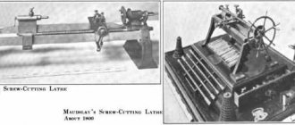
Universal series table lathes
The first model of the Universal table lathe with two round guides was developed by the ENIMS organization (Experimental Research Institute of Metal-Cutting Machine Tools). The basis was the Unimat SL machine from the Austrian company EMCO. Over 40 years, over 600 thousand machines have been sold.
The machine began to be mass-produced at the Moscow Machine Tool Plant StankoKonstruktsiya.
In the second half of the 80s, the design of the machine was significantly redesigned: starting with the Universal-3 model, instead of two round guides, one of a larger diameter appeared in the middle of the bed and the headstock was no longer disconnected from the bed. Several factories began mass-producing the machine:
- : , , , , Minicurrent (SKT100-01, SKT100-02, SKT100-03).
- Michurinsky plant Progress: ,
- Orion SKTB Nizhny Novgorod:
- Penza Instrument-Making Plant (Federal State Unitary Enterprise FSPC “PO “Start” named after M.B. Protsenko”), Penza: TD-180, TN-150
Description and purpose
The first model of the Universal table lathe with two round guides was developed by ENIMS and produced by the Moscow machine-tool plant StankoKonstruktsiya.
The first Station wagons had a cast iron frame and two cylindrical guides made of durable hardened steel. The principle of creating this design is borrowed from the Unimat SL model from EMCO (Austria), which has been selling up to 15 thousand machines of this model per year for more than 40 years. In 1968, the Universal-2 screw-cutting lathe appeared, with a low-power engine.
In 1975, the Universal-3 was launched with one guide of a larger diameter instead of two, of a smaller diameter. Due to the complex process of adjusting the alignment of the spindle and tailstock when returning to the bed after dismantling, the headstock was made non-removable. Let's take a closer look at the TSh-3 model, which represents the entire line of Station Wagons.
Description of the operation of the electrical circuit of the Universal-3 lathe
Electrical equipment is powered from a single-phase alternating current network with a voltage of 220 V and a frequency of 50 Hz.
Starting and stopping the electric motor is carried out using the KV relay (see Fig. 14), which is controlled by the SB2 (start) and SB1 (stop) buttons. When starting, the KV relay turns on and becomes self-powered, connecting the electric motor to the network with its contacts and providing zero protection, i.e. turning off the electric motor when there is no voltage in the network. The electric motor is protected from overload by the start-up relay A, which breaks the starting circuit, which turns off the KV relay. Restarting is possible only after 15-50 s, i.e. after the thermal protection elements of the start-up relay A return to their original position.
When starting the electric motor, its starting torque increases due to the connection of the starting capacitor C1 by the contacts of the start-protective relay A in parallel with the running capacitor C2. After the electric motor accelerates and the starting current decreases, capacitor C1 is turned off.
Reversing the electric motor is carried out using the switch SA, which, with the middle (vertical) position of the handle, ensures that the electric motor is turned off, i.e. it stops even when the KV relay is turned on. The handle should be left in a neutral position
Accessories
The mechanism in question includes additional accessories that help perform additional functions and make the machine more versatile.
These accessories include two tool holders. Using a movable tool, you can process conical surfaces.
A collet clamp is another additional accessory. It consists of a collet, a ring and a nut.
The famous Universal-3M lathe has been serving faithfully not only amateurs, but also professionals for decades. Its device allows you to process small and medium-sized parts.
The main advantage of such equipment is its versatility and the ability to connect to a regular household network. The standard configuration is sufficient to perform the basic operating functions of the device.
The machine is also distinguished by accuracy, reliability and durability, and therefore is popular to this day.
Purpose and scope
The Universal -3M desktop machine is designed for processing medium and small workpieces in individual workshops. Such a mechanism can often be found in the offices of schools, institutes, and various colleges.
Perfect for home use. the main advantages are:
- small amount of noise;
- the ability to connect to a household electrical network;
- small dimensions of the machine;
- its versatility.
That is why the device is popular among various craftsmen. The machine is designed to perform the following operations:
- segment;
- boring holes of different diameters;
- drilling holes and chamfering;
- grooving and boring of various surfaces, cylindrical, conical.
Technical characteristics of the desktop lathe Universal-3M
Delivery set, included in the price of the Universal-3M machine
Accessories:
- Milling and drilling device
- Surface grinding device
- Device for working with a circular saw
- Leash for woodworking
- Podruchnik
- Jigsaw device
- Sharpening device
- Three-jaw chuck 7100-0001 with flange and ring assembly
- Reverse jaw set and key for three-jaw chuck 7100-0001
- Drill chuck with key 6-B10 or 10-B16 GOST 8522
- Shank for drill chuck
- Center rotating
- Center thrust 2 pcs.
- The tool holder is movable
- Toolholder
- Drive chuck
- Mandrel with screws and clamp assembly (for boring work)
- Collet F6
- Collet F8
- Vise
- Polyethylene oiler
- Screen
- Chuck casing
Tool:
- Chisel
- Chisel
- Key for square S8
- Socket wrench S10x13
- Handle for key S10x13
- Key for square S7
- Scoring cutter (high-speed steel)
- Boring cutter (high-speed steel)
- Right through cutter (high-speed steel)
- Right through cutter with carbide plate
- Cutting cutter (high-speed steel) 2 pcs.
- External thread cutter (high-speed steel)
- Internal thread cutter (high-speed steel)
- Circular saw 3420-0356 GOST 980-80
- Jigsaw L=125 mm. TU 205.07.359-81 5 pcs.
- Twist drill F6.0 GOST 10902
- End mill with cylindrical shank F6.0 GOST 17025
- open-end wrench
- Socket wrenches GOST11737
- 7812-0373 40HFA N12x1 S=4
- 7812-0374 40HFA N12x1 S=5
- 7812-0375 40HFA N12x1 S=6
Accessories for extra. board for the Universal-3M lathe
1. 4-jaw lathe chucks with independent movement of jaws TN80 and TN100
Chucks are designed for clamping cylindrical and eccentric workpieces
on the machines “Universal-3M”, “MINITOK”, as well as some body parts
when processing them on universal machines. Can be used as an independent clamping device in metalworking industry.
The cylindrical body contains screws that engage with the racks of the assembly cams. When the screws are rotated with a wrench, each cam moves radially in the housing guides. The clamping jaws are attached to the rails with screws and are installed, depending on the diameter of the workpieces being clamped, as straight or reverse.
2. 3-jaw lathe chucks
2.1. Lathe chuck 3-jaw f 80mm, designation ST-80 7100-0001 - manufacturer - Grodno, 1989, set of direct and reverse jaws.
2.2. 3-jaw self-centering precision lathe chuck, designation ST-80V - manufacturer - Ponar Bial Equipment and Chucks Plant, Bialystok, Poland, 1989, set of direct and reverse jaws.
3. Milling device for the Universal-3M desktop machine
The price of the milling device for the Universal-3M desktop machine is 18,900 rubles.
4. Vise for the Universal-3M benchtop machine
Vise for the desktop machine Universal-3M price 7950 rubles.
5. Tool holders for the Universal-3M desktop machine
Movable tool holder for the Universal-3M desktop machine price 14,950 rubles.
Fixed standard tool holder for the Universal-3M desktop machine price 6,750 rubles.
Reinforced tool holder for the Universal-3M desktop machine price 8900 rubles.
6. Cutters for the Universal-3M machine
1. Right through cutter with a hard alloy plate 2. Groove cutter (high-speed steel R6M5) 3. External threaded cutter (high-speed steel R6M5) 4. Internal threaded cutter (high-speed steel R6M5) 5. Cutting cutter (high-speed steel R6M5) 6. Cutter boring (high-speed steel) 7. Left through cutter (high-speed steel R6M5) 8. Scoring cutter (high-speed steel R6M5)
Cutter height, 8x8 mm or 10x10 mm
The price of one cutter is 499 rubles.
7. Circular saws for wood for the Universal-3M machine
1. Wood saws f 125x32x1.2 x 48, GOST 980, steel 9HF, price 149 rubles.
2. Saw for sawing wood f 125x32x1.2 x 60, 3421-0288, price 149 rubles.
3. Saw f 125x32x1.6 x 48, 3420-0356, steel 9HF, price 149 rubles.
4. Saw f 125x32x1.6 x 60, price 149 rubles.
Universal – multifunctional table lathe. Purpose, scope
The Universal table lathe is a “hobby” class machine and is intended for individual (household) use, i.e., due to its design features and technical characteristics, the machine is not intended for use in production.
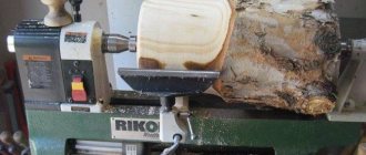
The Universal metal lathe is designed for processing workpieces made of metal, wood, and all types of plastic by turning.
The Universal machine is a desktop lathe and is intended for all kinds of turning work:
- grooving and boring of external and internal cylindrical, shaped and conical surfaces
- drilling holes, chamfering
- boring of holes
- segment
The spindle of the Universal lathe is a hollow steel part, with an internal hole of 10 mm for processing bar material, mounted on 2 roller bearings in the front and rear supports of the headstock.
The spindle receives 10 rotation speeds from a 120 W electric motor via a pulley drive. 4 speeds are obtained by rearranging the pulley belts between the 4-speed electric motor pulleys and the spindle take-up pulley. Other speeds are achieved by using an additional (intermediate) pulley.
The front end of the spindle of the Universal machine has an M20 thread for installation on the spindle of a lathe or driving chuck (see the article Lathe chucks).
A collet clamp with various internal holes can also be installed on the threaded end of the spindle.
In the drilling version, the spindle can move along its axis by 25 mm using a handle and a pair: gear wheel - gear rack. In the turning version, the spindle sleeve is clamped with two screws and is not used.
The support with the cutter installed on it moves along the longitudinal guides by 160 mm and along the transverse guides by 55 mm.
On the Universal machine, you cannot cut threads with a cutter because... there is no mechanical feed of the caliper - the lead screw is not connected to the drive and the caliper moves only manually.
On the “Universal” machine (Fig. 1), with the use of additional accessories and devices supplied with the machine, it is possible to perform a wide variety of types of machining on metal, wood, plastics and other materials.
A distinctive feature of the machine is its wide versatility and the possibility of readjustment using devices that allow you to perform the following work:
- turning and boring of holes;
- drilling holes
- milling of planes, recesses, grooves, etc.
- grinding and polishing
- sharpening of various cutting and household tools
- sawing sheet material, slats, boards using a circular saw
- sawing along the contour using a jigsaw
- coiling of springs
- thread cutting with dies and taps with manual rotation of the spindle to others
The machine operates from a single-phase alternating current network with a voltage of 220 V and a frequency of 50 Hz.
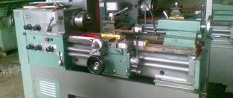
The “Universal” machine, when reconfiguring and installing additional devices, can have the following basic versions:
- turning version (Fig. 1);
- drilling, milling and grinding (Fig. 2)
- for working with a circular saw on wood (Fig. 3)
- for working with a jigsaw on wood (Fig. 4)
- sharpening
Currently, the Universal lathe has been discontinued and is no longer available. Instead, a more advanced tabletop lathe is being produced.
Universal series table lathes
The first model of the Universal table lathe with two round guides was developed by the ENIMS organization (Experimental Research Institute of Metal-Cutting Machine Tools). The basis was taken on the Unimat SL machine from the Austrian company EMCO (over 40 years, over 600 thousand machines of this model have been sold).
The Universal lathe was mass-produced at the Moscow Machine Tool Plant StankoKonstruktsiya.
Since 1968, the StankoKonstruktsiya plant began producing the Universal-2 table-top screw-cutting lathe - a significantly improved Universal machine.
In the second half of the 80s, the design of the machine was significantly redesigned: starting with the Universal-3 model, instead of two round guides, one of a larger diameter appeared in the middle of the bed and the headstock was no longer disconnected from the bed. Several factories began mass-producing the machine:
- : , , , , Minicurrent (SKT100-01, SKT100-02, SKT100-03).
- Michurinsky plant Progress: ,
- Orion SKTB Nizhny Novgorod:
- Penza Instrument-Making Plant (Federal State Unitary Enterprise FSPC “PO “Start” named after M.B. Protsenko”), Penza: TD-180, TN-150
Manufacturer information
The direct developer of this machine is the Experimental Research Institute of Metal-Cutting Machine Tools.
The manufacturer, from 1932 to this day, is the Moscow Machine Tool Plant. The first designs were based on the Austrian analogue of the Unimat SL.
The primary version of the Station Wagon series had two guides. The 3M station wagon, unlike the first models, has been significantly improved and instead of two guides, it has one of a larger diameter, which is located in the middle of the frame.
Machine device
When considering the Universal 2 benchtop lathe, you should pay attention to its layout. The device consists of the following elements:
- The bed acts as a load-bearing element that connects all the nodes together. It is made of cast iron and is characterized by high rigidity. This ensures precise positioning of all nodes relative to each other, as well as vibration damping at the time of processing.
- Round guides are welded to the base. They are required to move the main units. The latest version of the equipment has only one guide, but it ensures precise positioning of the units at the time of movement.
- With the exception of the latest model, on the first and second models the headstock is removable and fastened with special bolts.
- An electric motor is installed on the frame. A stepped belt drive is used as a drive. It is worth considering that the electrical circuit of the Universal 2 lathe is quite simple; the electric motor and drive can be removed from the device.
- The cross support is represented by a carriage, longitudinal and transverse slides. This unit fixes the tool in the required position at the time of processing. The cross support is characterized by high versatility in use and is suitable for securing tools with a rectangular holder. The tool can be offset relative to the workpiece by a certain angle if necessary.
- The Universal 3 lathe in question also has a tailstock, which is required to secure the workpiece in the required position. In most cases, a center is fixed in it to support the workpiece when it is long.
- Replacement guitar speed gears are designed to drive the caliper feed. They are selected when cutting threads with different parameters. The guitar comes with a combination of four or three interchangeable gears with terminal clamps. There are also instructions for setting up the device to obtain the required thread.
- The number of revolutions at the output is changed by a belt drive. This element also eliminates the possibility of motor overheating in the event of a spindle jam.
- Electrical control unit.
- Longitudinal lead screw. It is designed to ensure movement of the carriage along the workpiece.
- There is also a stand that, if necessary, can be mounted during drilling work.
- Handles and other controls. In order to ensure the required control accuracy, steering wheels and handles are installed. You can control the electrical part using various keys.
- Collet clamp for securing cutters and drills. The model under consideration can be used for various milling operations, for which the appropriate equipment and tools are installed. However, the number of milling operations performed is significantly limited.
- The table is rectangular.
The location of a fairly large number of different components on a small frame determines that the Universal can be used for a wide variety of work. The layout of the Universal is classic, due to which there are no problems with setting up and installing the workpiece.
The layout features also determine what types of work can be carried out on a lathe. The list of operations is as follows:
- Turning works, rough and finishing.
- Grinding and drilling.
- Processing the workpiece with a jigsaw or circular saw.
- Jointing in case of installation of wooden blanks.
- Sharpening operations.
Download the passport (operating instructions) of the Universal 3 lathe
An important point is that it is quite simple to re-adjust the equipment for drilling work; all you need to do is unfasten the mounting screws. After this, a vertical support is installed, which is used to mount the electric drive with the remaining necessary components.
Types of machine functions and its design
The main feature of the machine design is the function of changing the position of the spindle part relative to the bed. This makes it possible, in addition to standard turning operations, to perform a number of others using this equipment.
This is done with simple changeovers. To do this, it is necessary to study in detail the design and technical characteristics of the equipment. This versatility affects the processing parameters of materials.
At first glance, the layout of the machine is standard. The frame contains a slide, headstock and tailstock, as well as a drive with a gearbox. But to increase functionality, it is possible to change the position of the block with the spindle and power unit. After turning it 90°, the machine can perform drilling and milling.
List of operations performed on a desktop lathe after its modification:
- turning works;
- drilling and grinding;
- processing with a jigsaw and circular saw;
- jointing of wooden blanks;
- sharpening operations.
Converting the structure to perform these functions will not present much complexity. So, for drilling, it is enough to unscrew the mounting screws located on the protective cover of the spindle and the main drive. Then a vertical support is installed on the frame. A block with an electric motor and other components is mounted on it.
The standard equipment includes the necessary list of additional elements to perform the above operations. Their availability should be checked before purchasing the machine. This is especially true for purchasing used models.
Precautions when working with Consciousness
- equipment, compliance with safety measures during transportation and installation in the premises.
- In the electrical circuit, ensure the serviceability of the emergency device. Working.
- When de-energizing, equip the room for fire protection.
- Place emergency medical supplies and medications in an accessible area.
- Adjust work clothes in such a way as to prevent accidental contact with rotating mechanisms.
The prototype of the new screw-cutting MetalMaster -1830 lathe remains the TSh-3 machine, a pre-perestroika model of the Soviet brand Looks - 3. The station wagon is aesthetically pleasing, equipped with smooth controls and electronic drives. And, most importantly, the machine made a qualitative transition from amateur to professionally advanced for a metalworking machine.
Description of the kinematic diagram of the Universal-2 screw-cutting lathe
Main drive chain
The spindle rotation speed is controlled using a step-pulley belt drive.
From the electric motor 4, rotation is transmitted to a pulley 43, which has protrusions 42 at one end that can fit into the grooves of a 3-stage pulley 44. Thus, the pulley also performs the functions of a coupling.
To obtain 6 steps of the lower range of spindle rotation speeds (140 - 950 rpm), the pulley 43 is turned over with its protrusions outward and the movement from the pulley 43 is transmitted by a V-belt 45 to a 4-speed pulley 46 and then by a V-belt 47 to a 3-speed pulley 44, freely rotating on two radial ball bearings relative to the electric motor shaft, and then using a V-belt 48 on a 4-speed pulley 19, rigidly connected to the spindle 50.
To obtain 4 stages of the upper range of spindle rotation frequencies (800 - 3000 rpm), pulley 43 with protrusions 42 enters the grooves of pulley 44, connecting it to the electric motor shaft and the movement is transmitted from pulley 43 and 44 by belts to pulley 49 and spindle 50, while belts 45 and 47 must be removed.
The spindle speed is adjusted by moving the V-belts and coupling in accordance with the adjustment table (see Fig. 16).
Feed drive chain
The mechanical feed drive chain ensures the longitudinal movement of the support during turning and thread cutting and allows for: turning on the feed “to the left” or “to the right” and turning it off without stopping the rotation of the spindle; changing the direction of movement of the support while maintaining the same direction of rotation of the spindle (cutting right-hand and left-hand threads); regulation of the feed rate and pitch of the thread being cut.
The source of movement (initial link) of the feed chain is the rotation of the spindle, therefore the feed dimension is the amount of movement of the caliper in millimeters per spindle revolution (mm/rev).
From the replaceable gear A (see Fig. 13), installed on the spindle 50, rotation is transmitted through the replaceable gears B, C, D (when configured for feed) or B, C (when configured for thread cutting) to shaft 51, gear wheels 52, 53 or gear wheels 92, 88 and 89, clutch 54 for turning on the mechanical longitudinal movement of the caliper to the left or right and turning it off, and then to the longitudinal lead screw 11.
When cutting a left-hand thread, changing the direction of movement of the caliper while keeping the direction of rotation of the spindle unchanged is achieved by installing the coupling 54 in the right position.
The amount of feed and pitch of the cut thread is regulated by selecting replaceable gears A, B, C, D or A, B, C in accordance with the setting table.
Equipment Specifications
- Accuracy class N.
- Center-to-center distance – 180 mm.
- Maximum turning length is 120 mm.
- The Ø of the through hole of the spindle shaft is 10 mm.
- Spindle rotation speed – from 120 to 3*103 rpm. with 11 switching stages. To adjust it, rearrange the drive belt on the pulleys.
- Maximum blank diameter: above the guides - 125 mm, above the carriage slide - 60 mm.
- The stroke amplitude of the spindle shaft sleeve is 30 mm.
- Feed range – 0.05–0.175 mm/rev. Switching the feed speed is discrete, the number of steps is 6.
- The thread pitch interval is 0.2–2 mm.
- Fastening the chucks to the spindle shaft - M20 thread and Morse taper No. 2.
- The headstock is Morse taper No. 1. The maximum quill stroke is 20 mm.
- The power of the single electric motor is 0.25 kW.
aggregation of specialists
Incorrect or prolonged operation of equipment often leads to breakdown of components and if. parts, the operator hears the knocking of the bearings; then they need to be replaced. If work on the equipment is carried out with faulty bearings, the failure can lead to damage to other components and strong.
units noise or rapid heating requires the engine to inspect its windings. In some cases, the unit is completely replaced. If the motor suddenly stops, this indicates an electrical fault.
This situation indicates a breakdown of the trigger mechanism. If the engine is not able to gain speed, experts conclude that it is faulty.
The most common cause of breakdowns is interruptions in the supply of electrical energy. If this problem occurs frequently, it is recommended to purchase a special stabilizer.
Types of stabilizers
Independent disassembly of the structure is strictly prohibited, especially without the presence of certain experience, skills and knowledge.
In such a case, it is recommended to seek help from a specialist; he will not only eliminate the breakdown, but also ensure safe operation of the equipment in the future.
To avoid injury and equipment breakdown, the operator must strictly follow the rules of its operation. Cleaning of the main units of the unit must be carried out constantly.
The benchtop turning unit allows maximum precision processing of metal workpieces. achievements For this purpose it is necessary to adhere to its operating rules. Thanks to the simplicity of the design, the unit ensures precision processing of metal parts.
Setting up the Universal machine and operating rules for the machine
When machining various materials (steel, cast iron, wood, plastic, etc.) and performing various types of processing (turning, sawing, drilling, grinding, etc.) depending on the material of the cutting tool (tool, high-speed steel or carbide) a certain cutting speed is required to ensure good surface quality and maintain the cutting properties of the tool. So, at a very high cutting speed, the cutting tool will quickly become dull, and at a very low speed, the processed surface will turn out torn or rough. To obtain an appropriate cutting speed, it is necessary that the spindle rotates at the appropriate number of revolutions n per minute, which can be determined using the following simple formula:
n = 320 V/D rpm
where V is the cutting speed in m/min;
D is the diameter of the workpiece or cutting tool (when the cutting tool rotates). The following cutting speeds are recommended:
- When turning steel and cast iron - 50-80 m/min with carbide cutters and 20-40 m/min with high-speed steel cutters.
- When turning wood - 80-150 m/min.
- When drilling - 15-30 m/min.
- When grinding - up to 20 m/sec.
- When milling - 15-30 m/min.
- When sharpening - up to 20 m/sec.
- When sawing wood - 300-500 m/min.
- When working with a jigsaw n = 280-710 rpm.
Design and operation of the Universal-3 lathe
A hollow cylindrical guide is fixed to the machine bed. It is the common base for the main components of the machine: spindle head, caliper, tailstock. Another common base for these units is the flat bed guide.
In the front part of the frame, under the casing, there is a lead screw for longitudinal movement of the caliper.
A bracket is installed on the left wall of the headstock. The electric motor driving the machine is mounted on it.
Under the casing covering the bracket, there are spindle rotation drive pulleys and a feed drive mechanism.
The machine is supplied in a lathe version. The additional accessories included in the delivery set (see Table 7) are used to implement other versions of the machine with the help of simple changeovers: milling and drilling, grinding, jointing, etc.
The design of additional accessories is described below and methods for setting them up for various types of processing are given.
Tool holders
The delivery set includes two tool holders: movable and fixed.
Using a movable tool holder mounted on a carriage, conical surfaces can be processed. The fixed tool holder is attached to the slide of the caliper using a screw and a block that fits into one of the T-shaped grooves of the slide. There are two screws in the carriage, which, using the same crackers, secure the carriage to the caliper slider.
In general, the carriage can be installed in any of the grooves of the caliper slide in accordance with the adjustment requirements.
To process conical surfaces, the carriage should be installed on the slider so that the initial zero stroke of the carriage scale coincides with the mark on the left end of the slider. This installation is carried out using one screw in the base of the carriage, which is screwed into a threaded hole specially provided for this purpose, located on the upper plane of the slide between two T-shaped slots. The carriage scale division value is 1°.
ATTENTION! After turning the carriage to the required angle, it is necessary, in order to avoid an accident, to securely fix it with a fastening screw, as described above
Collet clamp
The clamp consists of a collet, a nut and a ring; the collet is inserted into the conical hole of the spindle, and the nut is screwed onto the spindle along the thread. With the help of this nut in the collet, moving along its axis, the workpiece or cutting tool inserted into its internal cylindrical hole is clamped.
Adjusting the Universal machine
If excessive play or excessive tension appears in the spindle bearings, they must be adjusted. To do this (Fig., unscrew nuts 2 and 4, remove pulley 6 and rotate nut 5. When tightening nut 5, the clearance in the bearing decreases; when loosening, it increases. Correctly adjusted bearings should not have axial play, which can be checked by moving the spindle forward and back in the axial direction. One of the reasons for vibrations during cutting may be improper adjustment of the bearings.
Setting up the machine for drilling, milling and grinding work and rules for its use
To reconfigure the machine for drilling, milling and grinding work, it is necessary to remove the spindle head with the drive and electric motor, for which, through the window in the wooden stand below, completely unscrew two nuts 3 (Fig. 8) with the tubular wrench supplied with the machine, and remove the two pins located in front of the spindle head. After this, secure bracket 2 (Fig. 10) to the spindle headstock with the same nuts 3. Instead of the spindle headstock, install stand I into the hole in the frame, put on washer 4 and secure nut 3 with a tubular wrench. Place bracket 2 with spindle head and drive on the rack and secure with screw 5 using a wrench. The height position of the bracket depends on the height of the workpiece and the length of the cutting tool.
Drills and end mills are fixed in a type II chuck with a diameter of 1-6 mm or in a collet I (Fig. 9). To install the chuck, it is necessary to insert a conical mandrel 6 into the conical hole of the spindle (Fig. 10), onto the free end of which the chuck is placed. When performing surface grinding work, screw the assembled grinding mandrel onto the threaded end of the spindle (Fig. 11).
The workpieces can be secured in a vice or on a rectangular table, which are installed on the upper slide of the support.
To install the vice, it is necessary to remove the tool holder, which is attached to the slide with a screw and a block located in the T-shaped groove. Using the two shorter screws and adding one block in the T-slot, screw the vise securely onto the top slide.
The vice (Fig. 12) has a screw-on jaw I, in which two mutually perpendicular grooves are made in the form of a prize, which makes it possible to conveniently fasten cylindrical parts in vertical and horizontal positions.
Installing a rectangular table (Fig. 13) is similar to installing a vice. The table is clamped with screws and four nuts supplied with the machine. The workpieces are mounted on the table using two clamps, each of which is made in the form of a strip with two screws.
When clamping, the bar should rest on the part with one end, the other end should rest on the adjusting screw and be positioned horizontally to avoid bending of the screws when clamping the part with a nut.
To ensure a closer approach of the caliper to the spindle head, it is necessary to remove the guard sleeve of the longitudinal screw, fixed on the left side of the caliper.
Vertical approach and feeding of the cutting tool is carried out by moving the sleeve in the spindle head using handle 7 (Fig. 10). In this case, using two screws located in the spindle headstock, it is necessary to pre-tighten the sleeve so that it does not fall down under the influence of its own nose and at the same time can be relatively easily placed from the handle 7. The feed when drilling should be such that it did not cause drill breakage or friction without removing noticeable chips. Before drilling holes, it is necessary to punch the workpiece and, by moving the caliper in two directions, accurately align the hole with the tip of the drill.
When milling, the vertical movement of the sleeve only involves cutting in, after which the sleeve should be secured to the spindle head using screws. Feed in the horizontal plane is carried out in two mutually perpendicular directions by moving the caliper. If it is necessary to mill along a contour, then it should first be drawn with a scriber on the surface of the workpiece.
When flat grinding, the abrasive wheel is also fed in the vertical direction only to a depth that should be small (0.01-0.02 mm). In some cases, it is possible to remove a layer of metal up to 0.5 mm deep. Feed in the horizontal direction should be carried out by the caliper evenly and quickly enough until the circle completely leaves contact with the workpiece. At the end of the treatment, to achieve good surface cleanliness, the so-called curing is done, i.e. Feeding is carried out without cutting into the grinding wheel until the spark disappears.
The grinding wheel can also be used to sharpen various tools.
Setting up the machine for sawing work and rules for its use
Sawing work is carried out on a special rectangular table (Fig. 14), in the slot of which a circular saw rotates. The machine is supplied with a saw for sawing wood or other material with similar mechanical properties. Other types of saws can cut thin metal sheets or strips.
Setting up the device is carried out as follows. Unscrew the nuts securing the spindle headstock through the window in the wooden stand, remove the spindle headstock, install a spacer, on which to install the spindle headstock again and secure it with nuts from below.
Adapter I with a fixed saw should be screwed onto the front threaded end of the spindle (Fig. 14) and tightened with a rod, inserting it into the holes of the adapter. Attach bracket 2 to the upper slide of the caliper using two screws 3 and nuts 4 located in the T-shaped grooves. After this, position the rectangular table 5 so that the saw fits into its slot and is in the middle of the cavity of the safety casing 6. Then, moving the caliper in two mutually perpendicular directions, align the holes of the table 5 and bracket 2 for fastening with screws 7. In this case, pin 8 should be free enter the hole in the bushing 9. If they do not coincide, then loosen the nut 10, insert the pin with the caliper and fasten the nut 10 again. Periodically apply 2-3 drops of oil to the friction point between the pin and the bushing. By moving the table 5 with the support in the longitudinal direction, ensure free rotation of the saw so that it does not touch the table and the safety guard. After this, secure the caliper with a specially provided screw. It is necessary that when the saw rotates, the sleeve 9 does not heat up too much due to improper adjustment of the sleeve. For convenient and correct direction of the material being cut, limiter II is used, which is secured with two screws 12. In this case, the edge of limiter II facing the saw must be installed strictly parallel to its blade.
The cutting of the material is carried out by uniformly feeding it along the saw and pressing it against limiter II.
ATTENTION! When working, be careful and keep your fingers at a sufficiently safe distance from the rotating saw. Working with the fence folded down is completely unacceptable.