History of turning
The oldest lathes were used in Egypt as far back as the Bronze Age. These were string lathes with reciprocating motion. Features of such designs:
- Their driving force was a person pulling one or the other end of a rope wound on a shaft mounted for rotation on two bearings.
- The workpiece was clamped at the end of the shaft, while another person held the cutting tool in his hands and pressed it against the workpiece.
In the middle of the 2nd millennium BC, a new design of lathe drive appeared, which lasted until the 16th century. It was a string drive, so it also used a cord wrapped around the drive shaft, but on one side it was attached to a foot pedal, and on the other to an elastic element (this could be a young tree bent in a special way). When a person pressed the pedal, he pulled the cord down, at the same time causing the shaft to rotate and the elastic element to compress. When the pressure on the pedal decreased, the spring element pulled the cord upward, while simultaneously turning the shaft in the opposite direction. Later, instead of wood, a spring-shaped arch was used, suspended from the ceiling.
Around 1500, the great Leonardo da Vinci improved the lathe drive, using rope and belt drives and at the same time gear drives - thus creating a lathe with continuous (irreversible) movement. The advent of the flywheel, which allows large amounts of energy to be stored, has made it easier to process increasingly harder materials.
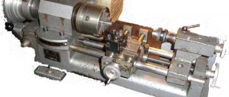
The first thing you notice when looking at the proposed machine is that it does not have any motor. The drive is a foot pedal and a crankshaft, hingedly connected by a metal (although it can be wooden) rod. A flywheel is attached to the crankshaft, promoting uniform rotation of the workpiece, sandwiched between the shank of the headstock and the cone of the rear. For example, a massive wooden circle (cut from a trunk of suitable diameter) or a disk made of thick boards (in two or three layers), respectively processed with a hacksaw, files and sandpaper, is suitable as a flywheel.From the flywheel, rotation is transmitted through a leather or rubber-fabric belt (or cord) to the headstock drum. Since the latter has the same diameter along its entire length, the change in the rotation speed of the workpiece depends only on the operation of the pressure pedal. If the drum is made in the form of a series of pulleys of different diameters, the desired speed can be obtained by simply throwing the belt. However, then you will need to come up with a device for tensioning the belt when transferring it from a larger pulley to a smaller one.
To connect the listed parts and assemblies into a single structure, wooden racks are used, which in turn rest on wooden thrust bearings. Both the racks themselves and the thrust bearings are made of identical boards 20-25 mm thick.
The longitudinal strength of the structure is provided by the lower and upper ligaments. On one of the lower ones - the one that is longer, combining all three racks (made of pipe or block), the pedal is hinged. And above it, on the top link (a board, like the racks, but half their width), a support is installed on which the processing tool will rest: a chisel, chisel, file or grinding block. The caliper can move horizontally and be fixed in the right place thanks to the eccentric with a handle located below. All caliper parts are made of hard wood.
The caliper base is an H-shaped body; it can be made entirely or from bars. A support for the tool (a block) is inserted into the upper groove, and the lower one slides along the block of the upper tie of the machine. The eccentric that fixes its position is a metal disk with a square hole offset from the center; the same hole is in the handle bar. The axle rod included in them has the same square cross-section as the middle part of the headstock shaft, where the drive drum is installed. The head of the headstock ends with a tooth that holds the workpiece.
Features of the first models of lathes
Let's look at the features of machine models that were invented later:
- In 1797, the Englishman Henry Maudsley designed a metal lathe, in which for the first time the carriage could be driven by a lead screw, that is, the cutting tool moved along the workpiece. An additional advantage of this design was the use of a transverse support, allowing the knife to move not only along, but also in a perpendicular direction.
- In 1810, the same G. Maudsley built a lathe with screw rotation. They were so carefully crafted that they became interchangeable. This was an important step towards mass production.
- In 1820, Maudsley designed another machine, a spindle lathe, suitable for mass production.
- The lathe with mechanical feed, both longitudinal and transverse, was invented in 1835 by the Englishman Joseph Whitworth.
- In 1839, Frederick Bodmer in Switzerland builds the first vertical lathe, in which the workpiece is clamped on a horizontal table, which made it possible to work with very heavy (more than 200 tons) and large objects (more than 24 meters in diameter).
- In 1845, the American S. Fitch designed a prototype of a turret machine, in which the carriage is equipped with a rotating part (turret head), to which several different tools can be simultaneously attached. This allowed the workpiece to be produced faster, eliminating the interruptions required to change tools. Simultaneously with the improvement of the design, a drive system was developed and improved from a transmission drive from a water wheel through a steam engine, to modern lathes with their own power source - an electric motor. The materials from which cutting tools were made were also changed. Initially they were made from low-carbon steel, but as the hardness of the workpieces increased, high-speed steel knives first appeared. In 1925, tungsten carbide was first used for tool blades.
After World War I, a variety of high-performance, specialized lathes developed rapidly and were used to produce weapons, automobiles, and other equipment. To increase the productivity of small batches of workpieces, lathes with hydraulic profiling devices were introduced in the late 1940s. At the same time, multi-tool lathes were developed. In the mid-1950s, computer-controlled lathes with punched cards, locking plates, and disks were developed. CNC technology began to be used in lathes in the 1960s and developed rapidly after the 1970s.
If you require laser cutting of metal, we will be waiting for applications on this issue.
Henry Maudsley
Maudslay Henry (1771-1831)
English mechanic and industrialist.
He created a screw-cutting lathe with a mechanized support (1797), mechanized the production of screws, nuts, etc. He spent his early years in Woolwich near London. At the age of 12 he began working as a cartridge filler at the Woolwich Arsenal, and at the age of 18 he was the best blacksmith of the arsenal and a mechanic in the workshop of J. Bram, the best workshop in London. Later he opened his own workshop, then a factory in Lambeth. Created the Maudsley Laboratory. Designer. Mechanical engineer. He created a mechanized lathe support of his own design. I came up with an original set of replacement gears. Invented a cross-planing machine with a crank mechanism. Created or improved a large number of different metal-cutting machines. He built steam ship engines for Russia. Since the beginning of the 19th century, a gradual revolution in mechanical engineering began. The old lathe is being replaced one by one by new high-precision automatic machines equipped with calipers. The beginning of this revolution was laid by the screw-cutting lathe of the English mechanic Henry Maudsley, which made it possible to automatically turn screws and bolts with any thread. The screw cutting machine designed by Maudsley represented a significant advance. The history of its invention is described as follows by contemporaries. In 1794-1795, Maudsley, still a young but already very experienced mechanic, worked in the workshop of the famous inventor Brahma. The main products of the workshop were water closets and locks invented by Bramo. The demand for them was very wide, and it was difficult to make them manually. Bramah and Maudsley were faced with the task of increasing the number of parts produced on the machines. However, the old lathe was inconvenient for this. Having begun work on its improvement, Maudsley equipped it with a cross support in 1794. The lower part of the support (slide) was installed on the same frame with the tailstock of the machine and could slide along its guide. In any place, the caliper could be firmly fixed with a screw. On the lower sled were the upper ones, arranged in a similar way. With their help, the cutter, fixed with a screw in a slot at the end of a steel bar, could move in the transverse direction. The caliper moved in the longitudinal and transverse directions using two lead screws. By moving the cutter using a support close to the workpiece, rigidly mounting it on a cross slide, and then moving it along the surface being processed, it was possible to cut off excess metal with great precision. In this case, the support performed the function of the worker’s hand holding the cutter. In fact, there was nothing new in the described design, but it was a necessary step towards further improvements. Olympox program system for self-training Having left Bramah shortly after his invention, Maudsley founded his own workshop and in 1798 created a more advanced lathe. This machine was an important milestone in the development of machine tool construction, since for the first time it made it possible to automatically cut screws of any length and any pitch. As already mentioned, the weak point of the old lathe was that it could only cut short screws. It couldn’t be otherwise, because there was no support, the worker’s hand had to remain motionless, and the workpiece itself moved along with the spindle. In the Maudsley machine, the workpiece remained motionless, and the support with the cutter fixed in it moved. In order to make the caliper move on the lower slide along the machine, Maudsley connected the headstock spindle to the caliper lead screw using two gears. The rotating screw was screwed into a nut, which pulled the caliper slide behind it and forced it to slide along the frame. Since the lead screw rotated at the same speed as the spindle, a thread was cut on the workpiece with the same pitch that was on this screw. For cutting screws with different pitches, the machine had a supply of lead screws. Automatic screw cutting on the machine occurred as follows. The workpiece was clamped and ground to the required dimensions, without turning on the mechanical feed of the caliper. After this, the lead screw was connected to the spindle, and screw cutting was carried out in several passes of the cutter. Each caliper's return movement was done manually after turning off the self-propelled feed. Thus, the lead screw and caliper completely replaced the worker’s hand. Moreover, they made it possible to cut threads much more accurately and faster than on previous machines.
In 1800, Maudsley made a remarkable improvement to his machine - instead of a set of interchangeable lead screws, he used a set of interchangeable gears that connected the spindle and the lead screw (there were 28 of them with a number of teeth from 15 to 50). Now it was possible to obtain different threads with different pitches using one lead screw. In fact, if it was necessary, for example, to obtain a screw whose stroke is n times less than that of the lead screw, it was necessary to make the workpiece rotate at such a speed that it would make n revolutions during the time while the lead screw received its rotation from the spindle , this was easily achieved by inserting one or more gear wheels between the spindle and the screw. Knowing the number of teeth on each wheel, it was not difficult to obtain the required speed. By changing the combination of wheels, it was possible to achieve different effects, for example, cutting a right-hand thread instead of a left-hand one. On his machine, Maudsley cut threads with such amazing precision and accuracy that it seemed almost a miracle to his contemporaries. In particular, he cut the adjusting screw and nut for an astronomical instrument, which for a long time was considered an unsurpassed masterpiece of precision. The screw was five feet long and two inches in diameter with 50 turns for every inch. The carving was so small that it could not be seen with the naked eye. Soon, the improved Maudsley machine became widespread and served as a model for many other metal-cutting machines. Maudsley's outstanding achievement brought him great and well-deserved fame. Indeed, although Maudsley cannot be considered the only inventor of the caliper, his undoubted merit was that he came up with his idea at the most necessary moment and put it in the most perfect form. We suggest you order soldering materials in bulk
Who is Henry Maudsley - short biography
The outstanding engineer was born on August 22, 1771 in London. His father, a former military man, was at the time working as a foreman at the Royal Arsenal. Like many English children of that era, little Henry began working at the age of 12. His duties included putting gunpowder into artillery cartridges . Later he was transferred to a carpentry workshop, and at the age of 15 he began to master the craft of a blacksmith.
After the arsenal, Maudsley ended up in the workshop of the outstanding inventor Joseph Bramah, creator of the world's first hydraulic press. It was there that he created his first inventions.
In 1800 he designed a machine for working metal . With its help, it became possible to produce fasteners that had precise and uniform dimensions. Thus, Henry prepared the technical basis for the subsequent introduction of standardization and interchangeability of parts , without which modern industrial production is unthinkable.
Ten years later, Maudsley founded his own engineering plant. His company quickly became one of the largest in England and existed until the beginning of the 20th century. Such outstanding engineers and inventors as Joseph Whitworth, creator of one of the first sniper rifles, and James Nesmith, who designed the steam hammer, began their creative careers in his workshop.
As Henry grew older, he became interested in astronomy, which was experiencing a real boom at that time. His plans included building his own observatory. However, they were not destined to come true. In January 1831, Maudsley became seriously ill and died a month later. He was only 59 years old. He is buried in the Woolwich area of London, the same place where he once poured gunpowder into cartridges as a child.
Inventions
Each of his creations became a significant milestone on the path of the industrial revolution. Many of them remained in the shadow of more high-profile technological innovations, such as the steam engine. However, each of his innovations deserves special attention.
Screw-cutting lathe
For a long time, when processing metal workpieces, turners had to hold the cutter in their hands. It was extremely inconvenient and unsafe to work like this; it was impossible to achieve the same precision in processing products. Maudsley came up with the idea to equip the machine with a special support in which the cutting tool was fixed .
Thanks to this, it became possible to rigidly install the cutter in two planes, increasing the accuracy of the work. Using his machine, it was possible to produce bolts and nuts with a fixed thread pitch . It is almost impossible to overestimate the impact of the emergence of standard fasteners on the speed of production of a wide variety of things.
Powered lathe support
The first improvement of his machine was the introduction of a mechanized support. Using a gear drive, Henry connected its lead screw to a spindle, by rotating which it was possible to move the cutter along the machine body and install it with high precision . At the same time, he made a separate set of different lead screws for the machine, replacing which made it possible to cut threads of different pitches and heights.