The design and manufacture of TV-4 machines is carried out at the Rostov Specialized. TV-4 has different technical characteristics than professional models, since it is needed for training and developing skills in handling steel workpieces. One of the main standards that are taken into account when designing a device is ease of setup and safety. Buying a new machine today is not difficult. However, don’t forget about used equipment. People who want to turn some metal part at home are unlikely to find a cheaper option.
Short story
This equipment has been produced by the Rostov educational equipment plant since the early 1970s. Due to the specifics of its application, this machine was called “Schoolboy”.
Industrialization required professional personnel, so the country supplied all secondary educational institutions with modern technologies by those standards.
This machine is still produced at the Rostov plant to this day, as it continues to be in demand in private workshops and for turning enthusiasts.
There is also a plant in Ukraine in Grozhno, which also produces a series of this equipment. But the Rostov plant is still considered the main manufacturer of this functional mobile design.
Purpose and scope of application of a school metal lathe
Since the equipment was originally produced as educational equipment, it is small in size. Therefore, it is not suitable for processing large parts.
The TV-4 screw-cutting lathe is designed for processing parts up to 12 cm in diameter and up to 30 cm in length. This is quite enough for those who have turning as a hobby and have a need for individual processing of parts.
The machine allows you to carry out the following types of turning work:
- trimming ends;
- cut;
- cutting metric threads;
- drilling;
- grooving and boring holes.
The school lathe is equipped with all the components of a full-fledged turning tool.
Purpose of the machine
Initially, it was planned to perform the entire range of turning operations on the school model. That is why the TV-4 design has the classic layout of all machines of this type. The following turning operations are performed on it:
- Boring and turning of steel workpieces by rotation.
- High precision end trimming.
- Drilling.
- Thread cutting (metric).
In order to increase functionality, equipment is being modernized. However, you can start this only after familiarizing yourself with the specific design and technical characteristics. Modernization should not adversely affect the performance and safety of operation of the machine.
The differences between training equipment are its layout and the location of controls, which should be such that a short teenager can operate the machine without difficulty.
Specifications
The electric motor power of the equipment in question is 0.6 kW. At the same time, the total weight of the machine is 280 kg, which allows it to be easily located in domestic conditions.
Main settings
The main parameters of TV-4 include:
- distance between centers – 35 cm;
- longest turning length – 30 cm;
- the maximum diameter of the workpiece processed above the upper part of the support is 125 mm;
- diameter processed above the bed – 20 cm.
The components in the machine are classic, with certain technical characteristics that allow you to perform all turning operations typical for this type of equipment.
Spindle
It is located in the front spindle headstock and its main function is to rotate the workpiece using a three-jaw chuck. It receives 6 digits of revolutions from the receiving pulley. Maximum – 710 rpm.
The largest diameter of the processed rod on the spindle is 15 mm. The end of the spindle is threaded – M36x4.
Caliper and feed
Designed to move the cutting tool. Has 4 carriages:
- The first one moves in the direction of the bed.
- The second one moves along the transverse guides of the first carriage, moving the cutting tool in the transverse direction.
- The third one rotates 45 degrees from the middle position in both directions.
- The fourth one carries the tool holder and moves in the longitudinal direction along the third carriage.
Cutting slide
According to the technical characteristics, the incisor slide assumes a displacement of 5 cm.
Tailstock
She is also called a stubborn grandmother. This is a structural part whose main function is to support the second end of the workpiece using the center. She fixes the future detail.
It is located on a base that moves evenly along the frame guides. The thrust headstock contains a quill that moves in the longitudinal direction. Its movement is carried out by a flywheel.
Electrical equipment
The drive is carried out from an asynchronous electric motor ~220V. Through clinometer gears and a single-stage pulley, the movement is transmitted to the running shaft and gearbox.
Electrical equipment also includes an electrical panel, transformer, and fuse links. The electrical panel and magnetic starter are located in the right cabinet, and the electric motor itself with a push-button station is in the left.
General dimensions (dimensions) and weight
The machine belongs to the light class of equipment. Its parameters in mm are 1100x470x1020. Processing accuracy class H, which allows an error of no more than 10 microns.
Thanks to its comfortable size, it is even suitable for installation in an apartment or on a balcony. That is why the machine is popular among household craftsmen.
General design and operating principle
The cabinet of this machine is made of thick-walled sheet steel. Additionally, stiffeners are installed. An electric motor is located at the back of the cabinet. On the front part there is an operation control unit, including a reverse button, as well as an on/off button.
The rear cabinet, which is U-shaped, also has stiffening ribs at the top and bottom. Inside this structure there is an electrical panel with all the main electrical equipment of this mechanism.
On the left side of the frame there is a spindle head, to which a gearbox is connected. The spindle rotates due to a three-jaw chuck.
From the spindle block to the gearbox, rotation is transmitted by a transmission mechanism. A special feature of the mechanism of this machine is that it is impossible to install other pairs of gears, and therefore the gear ratio is always the same.
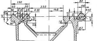
Drawings and description of the device
The basis of the entire machine is the bed. It is box-shaped with two prismatic guides. The front guide moves the carriage, and the rear guide moves the headstock. At the front of the frame there is a lead screw and a rack.
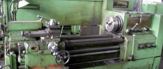
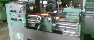
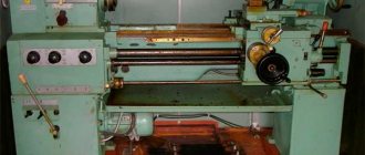
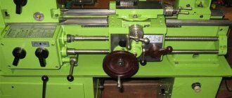
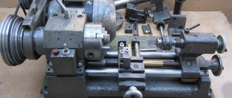
General form
General drawing
Location of controls
The controls of a screw-cutting lathe include:
- handles for setting spindle speeds;
- handle for cutting left and right threads;
- changing the direction of gears;
- drive roller shift handle;
- handle for increasing longitudinal mechanical feed;
- device for moving the cross slide;
- flywheel for moving the longitudinal carriage.
Kinematic diagram
Headstock
This is the main and main functioning element of any screw-cutting lathe. The part externally consists of a cast iron body, which includes a spindle and gearbox. Transmits the rotation element from the electric motor to the workpiece being processed.
The front spindle journal rotates in two radial thrust bearings, while the rear spindle rotates only in a radial bearing. So that the master can adjust the axis tension, there are two nuts on the spindle.
Gearbox
This design receives movement from the gearbox itself using transmission gears. The design of this part allows you to obtain metric threads with pitches of 0.8, 1.0, 1.25 mm. You can also obtain longitudinal feed of the caliper within the same limits, per spindle revolution.
On the front of the feed box cover there is a handle with which the threads and feeds are adjusted. The design of the feed box of this model eliminates the possibility of simultaneous rotation of the lead screw and the lead roller.
To lubricate the feedbox mechanism, there is a trough in the design for pouring oil. During operation, it is important to ensure that there is always a small amount of oil in this trough for lubrication.
Apron
With the help of an apron it is possible to carry out longitudinal mechanical and manual transmission from the roller and screw. For manual transmission you need to turn the flywheel, and for mechanical transmission you need to turn the handle, which starts the dog clutch.
Caliper
This design detail is necessary for securing and moving the cutter. In this version of the equipment it is equipped with four skids.
Tailstock
This is a persistent headstock, which is located on the base and secures the second end of the part during processing. The thrust head quill has a conical hole. It includes a thrust center or any other tool currently needed to process the workpiece.
Electrical circuit diagram
FAQ on turning TV-4, TV-6
The headstock is combined with the gearbox.
HEADSTOCK
The front headstock of the machine is mounted on the left side of the bed. Installation of the gearbox (the KS is often called the gearbox on the forum, but the machine also has a gearbox feedbox, so in the PB it is still the KS, and at the bottom the gearbox)) along the line of centers in the horizontal plane is carried out with two setscrews and nuts.
The headstock spindle receives six revolutions from the take-up pulley. A table indicating the spindle revolutions per minute depending on the position of the handles will be placed on the top cover of the feed box.
The front spindle journal rotates in two radial thrust bearings, and the rear journal rotates in a radial bearing. To regulate the axial tension, two nuts are installed on the spindle.
To fix the axial movement of the rollers, adjusting screws are installed on the front cover of the gearbox.
Oil level indicator
There is an oil level indicator on the front side of the gearbox; if it has become unusable, you can repair it like this. or another option. third repair option
On the back wall there is a plug for draining the oil (for more details, see the machine passport).
To collect metal filings at the bottom, you can put a neodymium magnet removed from the computer hard drive (hard drive)
Spindle bearings
In accordance with the passport, the spindle contains single-row angular contact ball bearings
The front two single-row angular contact ball bearings No. 46207, size, mm. 35x72x17
Rear single-row radial ball bearing No. 206, size, mm. ___ 30x62x16.
Adjusting rings are installed between the bearings.
(it is also stated on the forum that the machines were equipped with double-row 207 wheel bearings for passenger cars, but there is no documentary evidence of this fact)
Bearing adjusting rings - dimensions:
External (large) diameters: external - 71.5 mm, internal - 60 mm, thickness - 3 mm.
Internal (small) diameters: external - 45.5 mm, internal - 36 mm, thickness - 2.6 mm.
Angular contact bearings and ball and roller bearings are installed according to the “O” pattern, i.e. “back to back” to each other (if the bearings are marked “K”, i.e., “tapered” on their inner race, then they need to be installed “face to face”! (see the table below in the bearings subsection). (For installation diagrams, see below )
The remaining gearbox shaft bearings are ordinary ball bearings :
designations of imported bearings (domestic bearings do not have the number 6 in front, i.e. instead of 6202 there will simply be 202):
6202 2RS-7pcs
6204 2RS -1 piece (input shaft KS at the pulley)
Let me remind you that in the spindle there are 2x46207 (front) - 2 pcs. And
6206 2RS -1 piece (spindle tail)
All bearings are sealed, but during installation all “internal” covers were removed.
To remove the spindle, you need to remove the lathe chuck from the flange by unscrewing the bolts securing the chuck to the flange in the rear part (usually three if the chuck is a three-jaw chuck, but there may be more) and remove the chuck from the flange
Next you need to remove the flange
The faceplate of the lathe chuck is removed like this, unscrew the two screws (locking) on the spindle, jam the spindle and twist the flange (regular thread)
to increase torque, I inserted a couple of bolts with a nut and used a lever between the bolts; the first twisting usually causes trouble, sometimes you have to soak it in kerosene and knock lightly.
Read more about replacing the bearings of the entire CS in this topic.
Replacing PB bearings
PB assembly.
We also ask all questions there in the topics following the links.
About PB spindle bearings
Also, some forum users suggest replacing the standard radial thrust balls on 46207 with 36207, the difference between 36207 is that it has a smaller “stop” compared to 46207 due to the different angle of operation of the balls on the outer race. 46207 are installed in the spindles of more “adult” lathes and support higher radial loads (from the spindle moving along the axis). But many have 36207, they also work fine in TV-4, TV-6, the same bearings are installed in the smaller TV-16, although both TV-4(6) and TV-16 have a configuration with 130 cartridges those. The dimensions of the workpiece are the same and the axial loads are also approximately the same.
Also on the forum there are suggestions and options for installing roller thrust bearings 30207 on the spindle; their difference from their ball “brothers” is that they can withstand greater loads.
Bearings also differ in accuracy classes, the lowest class is 0, then comes 6.5, etc., the class designation on bearings made in the USSR/Russia is placed before the designation of the bearing itself, usually with an electric pencil or less often with engraving. For example, the spindle bearing described above with accuracy class 6 will be designated 6-46207. This designation is printed on the outer race of the bearing.
Imported bearings 207- have a designation of the type 7207, additional numbers/letters after the bearing size, as a rule, carry information about the design of the bearing and each manufacturer has their own. you need to look at the catalog (for example, from the European company SKF (interpretation of designations) bearing 7207 2RS - means that the bearing is closed with two caps; the same bearings, for example from the Asian company NSK or NTN, will have the designation 7207 DD, so look for catalogs of the manufacturer whose bearings you are going to purchase ).
According to members of the forum, installing high-quality precision bearings (naturally, the more “precision”/more accurate the bearing, the more expensive it is, and it’s more difficult to find, for example, a precision one than a high-precision one, and even a normal 6-class one can be found in any bearing company)) in a special TV set there is no point because The manufacturing quality of the machine as a whole is low, although the “safety margin” included in the design is quite good, but the low quality of manufacturing + operation “who turned it on and the turner” do their job, so it will be enough to put the 4th accuracy class for complacency, i.e. 4-46207 or a little “weaker” 4-36207.
In addition, it is worth noting that angular contact bearings are matched in pairs (bearings in such a pair are made/fitted/selected at the factory with a higher alignment than conventional “out of the box”) in the so-called “duplex”; such bearings come in one box , if these are from “old stocks”, then the bearings have the same number (i.e., it’s not the standard size by itself, but its own individual number, for example, the same number should be written on the holder of both, indicating that the bearings are from exactly the same pair), They also have arrows indicating the direction of orientation of the bearings, how they are centered and matched to each other.
Also, bearings made in the USSR are twisted with wire (if they really are from storage) and both, in pairs, are packed in oiled paper and placed in a box, but if they are “newer”, then also, in pairs, packed in oiled paper and are in a sealed plastic bag , and are also stored in a cardboard box. Since in TV-4, TV-6 there are adjusting rings between the bearings, therefore there is not much difference which scheme of bearings selected in pairs to buy (bearings can be selected according to the “tandem” scheme, i.e. they face with internal “cones” in one direction, i.e. . so >>. Duplexed towards each other >< i.e. “back to back.” More details for those who are interested, for example, here in paragraph 3.12. But of course, if you have the opportunity to buy a duplex circuit <> (“O” circuit), then you should take it .
Schemes for installing bearings using the example of the 205th bearing (the 207 is still the same, only its size is larger than 205)
About “tuning” the spindle with the installation of a double-row angular contact bearing in front and TWO in the back! bearings in this topic
Attention! Between the spindle bearings in TV-4 there is only one outer ring, while in TV-6 there are two rings between the bearings - outer and inner
If you want to make a new spindle altogether, read and discuss it in this thread
Can the spindle be drilled to a larger diameter? answer in this thread
Adjusting the radial clearance of the spindle.
After assembling and installing the spindle, it needs to be adjusted.
The radial clearance of the middle bearings and the axial clearance of the spindle are adjusted using nut 1 and locknut 2.
After adjusting the bearing tension, you need to check the spindle for radial spin. To do this, you need to insert a mandrel with a conical shank and a free length of 150 mm into the conical hole of the spindle.
Place the indicator button on the centering surface of the spindle and manually press the spindle using the free end of the mandrel.
In this case, the deviation of the indicator needle should not exceed 0.02 mm. When force is applied to the handle, the indicator will show the deviation of the radial runout in an abrupt manner, this is the desired value. a further smooth change in the indicator readings is already a bending of the spindle itself. In addition, the spindle should be easy to turn.
After assembling the KS into the PB, installation and adjustment of the headstock (PB) is necessary.
Adjusting the headstock (PB)
described here and also in this thread
Oil in the gearbox.
To change the oil (see the machine data sheet for the oil change interval), the KS PB has a drain plug on the back side at the bottom of the box (shown by an arrow), which must be unscrewed to drain the used oil.
Before filling in clean oil, it is advisable to rinse the CV (diesel fuel, kerosene, you can drain the old oil, fill in this “flushing” for a while, for example at night, turn on the machine in the morning, spin the CV for a couple of minutes at idle, drain the “flushing”, wipe the gearbox from inside and fill with fresh oil)
Clean oil must be poured 25 mm according to the oil level indicator (window in the PB KS) of grade I-30 (nowadays it is rare, so replacement with I-40A, I-20A or a mixture of them 50 to 50 is possible). Lubrication (including bearings, it is for this that you need to remove the caps from the bearings from the inside of the CV so that oil gets into them) occurs due to oil splashing, the thinner the oil, the more it splashes, but it also drains faster from the lubricated surfaces, making the box noisier, and thicker ones spray worse (with transmission type TAD-17 there were complaints about poor lubrication of spindle bearings), but it also lasts longer on lubricated surfaces, and the box is also less noisy.
Should I pour transmission oil into the gearbox?
As they advise on the forum, it's up to you to decide.
According to textbooks and reference books on bearings, liquid lubricant for bearings is better than grease; liquid lubricant is selected according to this simple principle - “the lower the load on the bearings, the lower the oil viscosity should be.”
For reference, the viscosity of industrial oils according to GOST is standardized at +40C
I-20 Kinematic viscosity, at 40 C, 29-35 (25-35) mm2/s
I-30 Kinematic viscosity, at 40 C, 41-51mm2/s
I-40 Kinematic viscosity, at 40 C, 61-75 (51-75) mm2/s
The viscosity of transmission oils at +40C is 100-130 mm2/s i.e. 2-3 times thicker than industrial oils.
Installation of oil seals in CS PB.
As a rule, the PB suffers from oil leakage. From the factory there is a packing as a seal; you can replace it and temporarily solve the problem with oil leaks near the spindle.
But it is better to grind the front carbolite cover and install an oil seal in it.
How to do this is written in this topic. We ask all questions there.
The back cover should also be sharpened, or even better, replace the carbolite one with a metal one, so that in the future you can fix the spindle and make a “split”.
Read about how to sharpen the back cover in this thread.
It is possible to sharpen this type of cover on your own TV-4 (TV-6).
if the cover is of this type
then you will have to look for a larger machine or make new metal covers
In addition to those indicated in the topics, these seals can also be used
post about replacing seals
Dimensions of required seals
Front spindle oil seal - 45x62x8 (with 45x60x7 it is not always possible to select the trace of the groove from the felt fit);
spindle tail oil seal - 30x42x8;
Feed box drive shaft oil seal - 20x32x7; (TV-4 also happens with a feed shaft Ф16mm, so it needs a 15x30x7 oil seal.)
spindle head pulley oil seal 28x42x7 or 30x42x7 or 32x45x7 (depending on the design of a specific unit, YOUR specific machine! disassemble and measure! before running for the oil seal!!!) I met different ones because on TV-4 and TV-6 the drive pulleys are slightly differ and, accordingly, are installed in different ways), you can do without it altogether by using a sealed bearing (the original one still doesn’t really lubricate there).
All of the listed oil seals are designed with a boot, the groove between the collar and the boot was filled with Castrol MS3 lubricant
Front spindle oil seal - 45x62x8 - TOYOTA > CHASER | (1984-1991) > 2.0 24V | 2L |150hp | 110KW. | 1986-1991 | 1G-FE | gasoline > Crank mechanism > Sealing ring, crankshaft > PAYEN NJ351 spindle headstock pulley oil seal 32x45x7 - Injection pump seal 32x45x7 (EURO) 332.112060
EURO couplings injection pump 32x45x7 CHRTI
But in the pulley cover you may need an oil seal “2108-1005034 28x42x7” (front crankshaft oil seal), the bushing is sealed
spindle tail oil seal - 30x42x8 - CITROEN > GS Break | (1971-1986) > A 1.2 | 1.2L |58hp | 43KW. | 1973-1979 | G12/612 | gasoline > Crank mechanism > Seal ring, crankshaft > PAYEN NF812
Gearbox drive shaft seal - 20x32x7 - CUFF OF POWER GEAR MECHANISM VOLGA, GAZELLE
-15x30x7-pump cuff NSh-10
Installing seals on the feed box in this post
Installation of rubber rings on the shafts of the gearbox handles and feedbox handles
described here
also another installation option
and another installation option
another option is shown in the figure below
If the handle “flies” at any speed, you can read about this problem and ask questions in this thread
The handle looks like this from the “back” side
Instructions for first start-up and operation
Installation and installation of the TV-4 machine must be carried out strictly by professionals. Before the first start, be sure to read the operating instructions and safety precautions.
To install the equipment, it is necessary to equip a foundation of at least 10 cm. The best option is bars or a concrete structure.
The mechanism is not equipped with level adjustment, and therefore during installation it is important to adjust the height differences. It is best if the machine is installed on adjustable supports.
There are several nuances of work that must be taken into account:
- In preparation for the work process, it is necessary to clean the mechanism from anti-corrosion liquid and fill the container with gearbox lubricant. It is important that the ground loop is configured.
- Before starting work, all handles must be in their original position. Only after this is it possible to carry out the initial setup of the machine. The workpiece should be firmly fixed between the spindle and thrust head. At the next stage, you should set the desired cutter.
- After finishing the work process, it is necessary to remove chips and metal dust that has collected on the machine after work. Then check the normal operation of all main structural parts so that in case of a breakdown it can be detected in time. Be sure to check the oil level every time before starting.
TV-4 machines are reliable. Therefore, with proper use, their service life is practically unlimited. It is only important to install it correctly from the beginning.
Usage
Due to the fact that the machine is classified as educational equipment, it must be installed and adjusted by specialists. Before starting work, students must study the design of the device, its performance indicators, and safety precautions.
To install the machine, you need to create a foundation 10 cm high. For this, it is possible to use wooden blocks or concrete. It is necessary to ensure that there are no differences in platform heights. You can install special adjustable supports.
There are certain operating rules that must be followed:
- Preparatory work. The equipment is cleaned of anti-corrosion agents, and gearbox lubricant is poured into a special container. When connecting to the electrical network, grounding is mandatory and an RCD is installed;
- Part processing. First of all, you need to make sure that all the handles are in the standard position. Then you can make settings. The part is fixed between the headstock and tailstock. The position of the tool is determined by means of the tool holder mechanisms;
- Preventative work. After processing is completed, metal filings must be removed and the integrity and correct operation of key parts of the machine are checked. Before starting, the amount of lubricant is checked.
This training equipment is not intended for mass production. Because of this, it should not be subjected to high loads. Any part of the machine can break, for example, the tool holder.
You can learn more about the operating features of the device by watching the video below.
Machine passport
The TV-4 machine does not have increased functionality, but it works successfully with workpieces made of carbide metals. It is specially made so that even a teenager can easily handle it. Equipment specifications:
- the diameter of the through hole in the spindle is 1.6 cm;
- number of possible revolutions per minute – 120, 160, 230, 375, 500, 710;
- number of stages for forward and reverse rotation – 6;
- maximum dimensions of the mounted tool are 10x12 mm;
- the caliper has 3 longitudinal gear stages;
- The tailstock quill moves up to 6.5 cm.
When planning the work process, it is necessary to take into account that this mechanism does not have a structure for braking the spindle or locking the control handles. Due to this feature, a slow stop of the future workpiece occurs.
You can download the entire passport for free from this link - TV-4 machine passport
Modern analogues
Despite the reliability and durability of the TV-4 screw-cutting lathe, it has modern analogues that are in no way inferior to the mechanism in terms of functionality and capabilities, these include:
- JET BD-7.
- JET BD-X7.
- Optimum TU1503V.
- Proma SM-300E.
- Triod LAMS-02/300.
The first two models are distinguished by high quality, as well as ease of speed adjustment. These are brands from well-known global manufacturers that can easily compete with TV-4 both in small workshops and on school desks.
The screw-cutting lathe of the Rostov educational equipment plant has been serving faithfully in small workshops and in everyday life for almost half a century. This is a functional and at the same time reliable equipment that will help you master any lathe.
The mechanism is lightweight and small in size and will fit in any mini-workshop. Also, its obvious advantages are ease of operation and durability during service.
Purpose
The main requirements for training equipment are safety and ease of setup. Students, working on equipment, learn how it is structurally arranged and become familiar with the processing of parts.
Initially, TV 4 Shkolnik lathes were created to carry out various turning operations. Their design is classically arranged. This is typical for such devices. With such equipment it is possible:
- Turn and bore various steel parts by rotating;
- Trim end sections with great precision;
- Cut the thread. It must be remembered that the device can only form metric threads. It is simply impossible to make other types of carving;
- Drill.
In order to increase the functionality of the equipment, it needs to be modernized. This can be done by studying its design features in detail and familiarizing yourself with the technical characteristics. Modernization should not negatively affect the performance of the device or operational safety.
The control parts of training machines are located in a special way. Because of this, teenagers can process steel workpieces without any problems. Short stature and short arm length are not a problem when working on training equipment.