Brief history of the series
Two years later, in 1934, production of such models as DIP-300, DIP-400, DIP-500 was launched.
By 1937, special types of nomenclature and sizes were being developed. A unified system of symbols is adopted. Thus, the first machine produced by the plant was named 1D62, but the abbreviation DIP-20 was retained.
The year 1940 was marked by the creation of the 162K 26A machine, as one of the versions of the DIP-200.
Then various modernized machines were produced, and in 1948, the legendary 1A62 appeared. The models were produced in large quantities.
And finally, in 1971, the first prototype of the 16 to 20 machine was manufactured. The machine even received a gold medal at the fair in ’72.
From 1972 to 1973, reconstruction was carried out at the plant, this is due to the large-scale production of new 16K20 models. The company is developing mass production of this model, and at the end of 1973, the monthly production turnover reaches 1 thousand copies. About 10% of the total is exported.
Then various modifications of the 16 to 20 model appeared, including 16 K 25, 16 K2 0M, 16 K2 0P, 16 K 20V, 16 K 20G, 16 K 20K, 16K20F1, 16K20PF1, 16K20VF1 and others. All were based on the basic standards of the 16 to 20 model.
1988 will mark the end of production of machines of this model. It was replaced by the MK series.
Manufacturer information
Near the workshop in Zamoskvorechye, the Bromley brothers began construction of a mechanical plant in 1857. His first products were axes, sickles and other tools for peasants. In 1864, the brothers purchased a new plot and began to obtain permission to build new workshop buildings.
In 1870 and 1872, planing and drilling machines from Zamoskvorechye received gold medals at the Moscow Industrial Exhibition. The triple expansion steam engine was awarded the Grand Gold Medal at the International Exhibition in Paris.
In 1918, the plant was nationalized and modernized. Since 1922, the plant has completely switched to the production of metal-cutting machines. In 1971, the first machines of the 16K20 series were produced. After the reconstruction of the plant, in 1973 they began to produce 16A20F3 with CNC.
Important!
Since 2016, the Moscow Machine Tool Plant has been located in New Cheryomushki. The production of CNC lathes has resumed.
Operator's manual for screw-cutting lathe 16K20RF3S32 with CNC 2P22
This manual contains information for the operator on servicing the 16K20RF3S32 machine with a 2P22 or 2P22.01 CNC system. Contents of the operator's manual:
- Purpose of the program
- Program execution conditions
- Program Execution
- Operating procedure
- General provisions
- Linking the device to machine parameters
- Linking the reference system to the machine
- Linking a tool to a reference system
- Linking a reference system to a part
- Semi-automatic input of the initial position and exit of the tool to this position
- Input mode
- Program output
- “Manual control” mode
- Automatic mode
- Test mode
- Coding system and frame order
- Programming chamfers, arcs and fillets
- Programming canned cycles
- Drawing up programs when entering from punched tape
- Messages to the operator
- Device exchange signals
- Algorithms for the operation of electrical automation of a controlled machine
Machine design
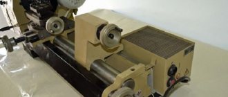
The basis of the device is a durable U-shaped frame with 2 hardened, ground guides on top. It is installed on pedestals in a cast metal support, which is used as a trough for emulsion and collecting chips. The main electric drive is located in the cabinet on the headstock side of the product.
Dimensions of screw-cutting lathe 16K20
Machine dimensions: length 2505, 2795, 3195 or 3795 mm; width 1190 mm; height 1500 mm. The weight of the machine depends on its length and can be 2.835; 3.005; 3.225 or 3.685 per 103 kg.
Spindle
The spindle shaft is steel with a through longitudinal hole through which a rod is passed, used as a workpiece, or a drift when knocking out the front center. To rotate the spindle in this machine, specialized precision rolling bearings are used. They are distinguished by high manufacturing precision and wear resistance, so they do not require periodic adjustments during maintenance during the operational period.
The shaft supports are lubricated by oil supplied to them under pump pressure. The front end of the spindle shaft is made in accordance with GOST 12593 - with a short centering cone 1:4.
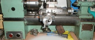
Headstock
The headstock or headstock of the workpiece serves to fix one end of the workpiece and transmit torque to it. It houses the spindle, bulkhead box and other components. On the outside there are switching levers for the bulkhead box.
The output shaft of the headstock of the product is connected through gears to the feed reducer. The latter allows the slide to carry out the feed movement using the drive shaft during turning. Or by means of a lead screw for thread cutting. Which can be connected to the feed box without intermediate links.
Apron
This unit is necessary to move the caliper with the tool holder both along and across the axis of rotation of the part. It converts the rotary motion of the screw into linear displacement of the caliper. You can move the latter not only manually, but also by taking away part of the rotational torque from the spindle. The apron of this machine is equipped with a high-precision feed cut-off device on a stop, a design that has not been seen before.
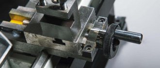
Caliper
Designed to hold the tool holder with the cutter fixed in it near the workpiece. Possessing several degrees of freedom, it can move under the influence of the apron to form the desired surface character of the part with a cutter. To control the amount of movement, the unit is equipped with scale rulers with sighting devices that increase the accuracy and ease of reading readings.
Tailstock
She's a stubborn grandma. It is installed on guides that allow it to move along the machine. It has a tapered hole coaxial with the headstock output shaft. Which allows you to set a center to support the second end of the blank. Or a reamer, tap, drill and other similar ones for performing operations from the open end of the workpiece.
Features of the 16K20 machine and operating principle:
- The rigid frame, made in a box-shaped form, stands on a monolithic type base; it is equipped with ground hardened guides;
- Parts subjected to turning are mounted in a chuck or in centers;
- The stability of fixation of the cutter in the unit is ensured by the special design of its holder;
- The spindle is mounted on precision rolling bearings;
- The safety of using the equipment is guaranteed by a complex of blocking and fencing mechanisms;
- The ease of establishing the indicator of movement of the transverse and cutting slides during operation is ensured by rulers (scale), which are equipped with sights;
- There is a high-quality caliper feed shut-off device on the installation apron.
In the design of the 16K20 lathe, the spindle is mounted on special precision rolling bearings, which require adjustment during operation. Thanks to this design, the required rigidity is ensured, as well as high precision in processing workpieces. According to GOST 8-82, the 16k20 lathe has accuracy class N, which will be ensured even under shock loads. The front end of the spindle is made according to GOST 12593 (DIN 55027, ISO 702-3-75) with a centering short cone 1:4 (7°7′30″).
Turning on, turning off, reversing and braking the spindle during machine operation is performed without stopping the electric motor due to the friction clutch, which is controlled by two interlocked handles having three positions:
- Neutral position - braking of the spindle with a band brake, disconnection from the input shaft;
- Right position - spindle reverse, work in the opposite direction;
- Left position - the spindle works in the forward direction;
In this case, the engine rotates in one direction without stopping.
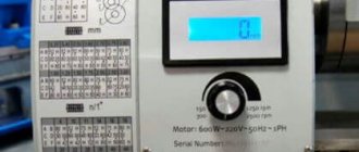
Using the right handle on the spindle head of the machine, the gearbox mechanism allows you to obtain 4 rows of spindle speeds: 1:32, 1:8, 1:2, 1.25:1. And in each range, you can select one of six speeds with the left handle, thanks to which the spindle receives 4 x 6 = 24 speeds, two of which are 500 and 630 rpm. - are repeated.
The output shaft of the lathe gearbox is connected to the feed box using replaceable gears, which allows the caliper to be moved over a wide range of feeds from the lead shaft when turning and from the lead screw when threading. And in order to cut precise threads without problems, the design has a direct connection of the lead screw to the input shaft of the feed box.
The support of the 16K20 machine has scale rulers with sights that help determine the amount of movement of the cutting and cross slides during operation. At the same time, the successful design of the tool holder improves the stability of fixation.
The 16K20 apron has a special mechanism for turning off the caliper feed - a falling worm. It provides high stopping accuracy on a rigid stop. And special fencing and blocking devices ensure safe operation of the machine.
Download the passport of the machine 16A20F3 with CNC NC-202 for free.
A 16A20F3 screw-cutting lathe with an NC-202 CNC device is equipped with an Inverter Hyundai N300 main drive and two HA-075 feed drives along the Z and X axes. An additional feature of this machine is that it is equipped with an Inverter Delta VFD-M drive that performs the function of clamping and releasing the quill and chuck and control of the toolholder head. It is designed for automatic turning of external and internal surfaces of parts such as bodies of revolution with stepped and curved profiles of varying complexity according to a pre-compiled control program. Deviation from cylindricity is 7 microns, taper is 20 microns at a length of 300 mm, deviation from straightness of the end surface at a diameter of 300 mm is 16 microns. Area of application of the machine: small-scale and mass production.
Milling machine 6T12F20-1 The cantilever-vertical milling machine with operational program control (OPC) model 6T12F20 is designed for performing a variety of milling work with cylindrical, angular, shaped, face and other cutters. A wide range of spindle speeds and table feeds allows for efficient processing of parts made of cast iron, steel, difficult-to-machine alloys, non-ferrous metals, light alloys and plastics. The machines can process parts of complex configurations that have vertical and horizontal planes, frames, grooves, ledges, etc.
Purpose and scope
The 16A20F3 CNC chuck-centering lathe is designed for external and internal processing of medium-sized workpieces with a diameter of up to 400 mm and a length of 1000 mm. The equipment produces a stepped and curved profile with an offset relative to the axis of rotation. The entire processing cycle takes place automatically.
Model 16A20F3 performs external and internal processing:
- turning of cylindrical surfaces in one axis and with offset;
- elements having conical, spherical and other complex profiles;
- drilling along the end and radius;
- boring;
- thread cutting.
The chuck-centering CNC machine 16A20F3 is designed for finishing processing of complex-profile parts. It produces crankshafts, connecting rods, earrings and other products, individually and in large quantities.
Find out why the 1516 universal rotary lathe is so good.
Versatility
The technical characteristics of the 16K20F3 screw-cutting lathe allow it to be used for the following operations:
- Drilling holes of various diameters.
- Processing of workpieces from the end parts.
- Countersinking.
- Thread cutting.
- Boring and finishing of conical and shaped surfaces.
The screw-cutting pairs are protected by special limiters that help prevent premature failure of the mechanisms. The modernization of the units under consideration consists of equipping them with CNC kits of domestic and foreign production with replaceable electrical systems. Re-equipment makes it possible to increase power by 2-3 times, depending on the condition of the units. All these solutions increase equipment productivity and reduce the transformation of workpieces. It is advisable to carry out modernization simultaneously with major repairs.
Design and principle of operation
The 16K20FZ turning machine is used for work carried out when processing the internal and external surfaces of products according to a pre-established program. Mostly, products with internal surface dimensions not exceeding 100 cm and external surface dimensions not exceeding 40 cm are finished.
The design and kinematic diagram of the 16K20FZ lathe is made according to a traditional layout that complies with universal standards and has characteristics that allow it to perform a wide range of operations. The equipment consists of units and mechanisms:
- grounds;
- beds;
- caliper carriages;
- rotary tool holder;
- tailstock;
- guides;
- automatic transmission;
- headstock;
- electromagnetic couplings;
- drives (transverse and longitudinal);
- hydraulic booster.
The metal workpiece is fixed in a spindle, which is driven into rotation by an electric motor that provides operation through a V-belt drive, the speed of which is regulated by an automatic transmission and a spindle head gearbox. The automatic transmission has 6 electromagnetic clutches, which, using their combined activation, select the required 1 of 9 possible shaft rotation speeds.
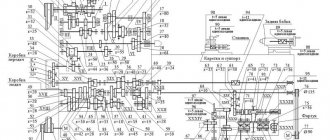
Kinematic diagram 16K20F3
To change the rotation speed, spindle head gears are used, which have manual switching and are capable of adjusting rotation in 12 modes.
The machine carriage has the ability to make longitudinal displacements using an electromagnetic drive. The transverse transmission of the caliper with the tool holder is carried out using a drive, a gear wheel, and a lead screw.
Turret head 16K20F3
The rotary tool holder can be installed in six positions, changing angles with a horizontal axis of rotation of the plane and mounted on a transverse support. The tool holder positions the tool head, in which up to six cutters used for finishing the workpiece can be mounted according to a given program.
The hydraulic drive, which includes a hydraulic station and two hydraulic boosters, is equipped with:
- control pump;
- drive;
- container with oil;
- control equipment.
Hydraulic drive mechanisms provide all the basic processes associated with the operation of the units.
CNC system
The 16K20F3 lathe is equipped with various CNC systems. Machine modifications, depending on the configuration of the CNC device, have different indices (for example, 16K20F3S32). The contour CNC system ensures the movement of shaping, changing the feed rates and spindle speeds in the processing cycle, indexing the rotary tool holder, and cutting threads according to the program. The number of simultaneously controlled coordinates is 2, the total controlled coordinates are 2. The discreteness of specifying transverse feed movements (along the X axis) is 0.005 mm, longitudinal movements (along the Z axis) is 0.01 mm. The 16K20F3 machine with a 2P22 CNC device is equipped with a KEMRON main drive and a KEMTOK feed drive along the Z and X axis.
Designation
The alphanumeric index of the machine 16K20F3 means the following: number 1 is a lathe; number 6 - designates a screw-cutting lathe, letter K - generation of the machine, number 20 - height of the centers (200 mm). The presence of “F3” at the end of the index indicates the presence of CNC - numerical program control.
| Specifications | Options |
| Machining diameter above the bed, mm | 500 |
| Machining diameter above the support, mm | 200 |
| Maximum processing length, 6-position head, mm | 900 |
| Maximum processing length, 8-position head, mm | 750 |
| Maximum processing length, 12-position head, mm | 850 |
| Maximum processing length in centers, mm | 1000 |
| Diameter of cylindrical hole in spindle, mm | 55 |
| Maximum lateral stroke of the caliper, mm | 210 |
| Maximum longitudinal stroke of the caliper, mm | 905 |
| Maximum recommended speed of longitudinal working feed, mm | 2000 |
| Maximum recommended speed of transverse working feed, mm | 1000 |
| Number of controlled coordinates, pcs. | 2 |
| Number of simultaneously controlled coordinates, pcs. | 2 |
| Discreteness of movement task, mm | 0,001 |
| Spindle speed limits, min-1 | 20 — 2500 |
| Speed of fast movements of the caliper - transverse, mm/min | 2 400 |
| Maximum speed of fast longitudinal movements, mm/min | 15000 |
| Maximum speed of fast transverse movements, mm/min | 7500 |
| Number of tool head positions | 8 |
| Power of the electric motor of the main movement, kW | 11 |
| Accuracy class according to GOST 8-82 | P |
| Overall dimensions of the machine (L x W x H), mm | 3700 × 2260 × 1650 |
| Machine weight, kg | 4000 |
Design Features
The high-strength machine bed 16K20F3 is made of cast iron SCh20 with heat-treated ground guides, ensuring long service life and increased processing accuracy. The main movement drive, which includes a 11 kW main motor and a spindle head, provides the highest torque of up to 800 Nm. High-precision spindle with a 55 mm bore (64 mm on request), allowing the processing of parts made of bar material. The processing area can be equipped with either a linear adjustment or a turret, depending on the customer's requirements. Reliable protection of ball screw pairs ensures the durability of the movement mechanisms along the X and Z coordinates. The 16K20F3 machine is equipped with CNC systems and electric drives, both domestically produced and manufactured by foreign companies. Feedback and threading sensors model VTM-1M.
Control
The tool movement program, main drive control and auxiliary commands are entered into the control system memory from the operator console keyboard, as well as from an external memory cassette and can be adjusted from the CNC operator console with visualization on the digital display panel.
Automatic tool head
The 16K20F3 CNC lathe is equipped with a 6-, 8- or 12-position automatic universal head (UG9321, UG9324, UG9325) with a horizontal rotation axis. The head has a tool disk for 6 radial and 3 axial tools (6-position) or 8 blocks for radial and axial tools (8-position) or 12 blocks for radial and axial tools, combined when setting up a part (12-position).
Location of components
Ball screw pairs of the X and Z axes have an increased service life due to reliable protection of the units. The spindle is high-precision, with a hole of 55 mm and 64 mm.
The frame has a chip removal conveyor. The support group consists of an apron and the base of a removable automatic turret. They are driven by a drive and a transverse movement VGK. The longitudinal movement of the tool is carried out through angular gears and a coupling from the VGK screws.
On the left above the frame in the housing there is a gearbox and spindle head. The chuck is installed mechanized and has its own electric drive. The tailstock is located on the bed guides. The quill is driven by an electromechanical drive. Push-button machine control panel. It is located on a bracket and easily changes its position.
Prevention and repair
Daily care activities
Before starting work:
- Inspection of the machine.
- Lubricate the lead screw and shaft.
- Controlling the amount of oil.
- Switching on with checking nodes without load.
During operation:
- Switch feeds and gears only after the moving units have finally stopped.
- When working with cast iron or abrasive materials, cover the guides with thick cloth.
After the end of working hours: turn off the power supply, remove the shavings, wipe with a rag soaked in kerosene, and lubricate the open guides with oil.
Malfunctions and their elimination
| Symptoms | Cause | Correction method |
| Ovality of the part or hole being bored. | Blank runout in the cartridge. | Boring of jaws. |
| Quill play or weak fastening of the thrust headstock. | Adjusting or repairing the quill. | |
| Hole axis offset. | Misalignment of spindle shaft and tailstock. | Adjustment. Or repair with adjustment. |
| Significant cone of cylindrical parts. | Mismatch between the centers of the spindle shaft and the thrust head. | Adjustment. |
| Worn caliper or bed guides | Adjustment or repair. | |
| Dimensional instability during trimming. | Axial play of the spindle shaft. | Replacing rotation bearings. |
A slight increase in caliper clearances can be eliminated by adjusting the wedges in the transverse or upper slide guides, and the adjustment screws in the rear guide of the longitudinal slide. Then, moving the slide to the maximum distance, make sure that it moves smoothly. Leaks in the screw drive of the cross slide are eliminated by adjusting the screws located behind the tool holder platform.
Kinematic diagram of screw-cutting lathe 16A20F3
Below is a sketch of one page of the documentation “Kinematic diagram 16A20F3”
| < Previous | Next > |
Related materials:
- ELL 12XXX. Electric drive. Passport, Manual, Instructions, Description, Characteristics.
- ELL 4XXX. Electric drive. Passport, Manual, Instructions, Description, Characteristics.
- NC-301. CNC system. Passport, Manual, instructions, description, characteristics.
- EPT-2. Electric drive. Passport, Manual, Instructions, Description, Diagrams, Characteristics
- EPU1M. Electric drive. Passport, Manual, Instructions, Description, Diagrams, Characteristics
The following materials:
- 6Р13. Vertical milling machine. Passport, Characteristics, Diagram, Manual
- 6Р12Б. Vertical milling machine. Passport, Characteristics, Diagram, Manual
- 16B16T1. CNC screw-cutting lathe NTs-31. Passport, Characteristics, Diagram, Manual
- 1325F30. CNC turret lathe NTs-31. Machine diagram, Characteristics
- 16K20T1.02. CNC screw-cutting lathe NTs-31. Electrical automation board diagram
Previous materials:
- 16K20RF3. CNC screw-cutting lathe 2Р22. Passport, Characteristics, Diagram, Manual
- 16A20F3. CNC screw-cutting lathe NTs-31. Electrical automation board diagram
- 16A20F3S39. CNC screw-cutting lathe NTs-31. Electrical automation board diagram
- 24K40AF4-01. CNC coordinate machine TNC-145. Passport, Characteristics, Diagram, Manual
- 24K40SF4-01. CNC coordinate machine TNC-145. Passport, Characteristics, Diagram, Manual
Specifications
The processing accuracy on the 16A20F3 machine is 0.01 mm. The program has a resolution of 0.0–1 mm on both axes.
Technical characteristics of the lathe model 16A20F3:
- workpiece diameter above the bed 400 mm;
- above the caliper 220 mm;
- maximum workpiece length 1000 mm;
- spindle hole diameter 53 mm;
- the longest length of the workpiece when processing with a turret is 870 mm;
- main drive motor power 11 kW;
- number of spindle speeds 22;
- cutter height 25 mm;
- number of coordinates 2;
- CNC system – 2Р22;
- total power of the machine is 22 kW.
The dimensions of the machine are 3700×1700×2145 mm and the weight with CNC equipment is 4050 kg. The 16A20F3 CNC lathe is a leader in its use at large enterprises with metalworking equipment. Currently, units are widely used for the manufacture of complex individual parts and when working on a stream.
Process control and automation programs
The delivery package of the 16k20fz CNC machine includes many ready-made scripts for carrying out certain operations in automatic mode. The programmer's task, when using standard programs, includes minimal modifications designed to regulate the size of the workpiece and certain parameters of the final product.
However, the documentation for the control system includes detailed instructions that describe the syntax used in programming and an available list of standard commands. It is also declared:
- codeword order, which is the recommended order of addresses in one code frame;
- syntax format in a single frame;
- required final commands and frame header format.
In addition to describing the available structure of an individual frame, the documentation provides data regarding the processing discreteness adopted in the system. In particular, the maximum allowed number of symbols for a code word is given, as well as the maximum commands within one frame.
Some numerical control systems come with their own automated command development systems. Such tools greatly facilitate the operator’s work. Their tasks include:
- automatic verification of program syntax compliance with the code used;
- monitoring compliance of the listing with the set of restrictions adopted in the system;
- support for help, provision of information given in the documentation for the machine.
Development tools allow you to typify individual programmer actions, use existing schemes for processing certain surfaces, and reduce the redundancy of commands. As a result of the use of such products, the productivity of personnel, the machine, and the work process as a whole increases significantly, while the level of failures and the number of incorrect instructions decreases.
Drawings of screw-cutting lathe 16K20P
Below is a link to drawings of various components of the 16K20P screw-cutting lathe in excellent quality, made in AutoCad and imported into a regular JPG format.
Contents “Drawings of screw-cutting lathe 16K20P”
- General view of the machine 16K20P
- Kinematic diagram
- Scanning the gearbox
- Transmission cuts
- Tailstock
- Specification
| < Previous | Next > |
Related materials:
- ELL 12XXX. Electric drive. Passport, Manual, Instructions, Description, Characteristics.
- ELL 4XXX. Electric drive. Passport, Manual, Instructions, Description, Characteristics.
- 2431. Jig boring machine. Passport, Characteristics, Diagram, Manual
- NC-301. CNC system. Passport, Manual, instructions, description, characteristics.
- 2N55. Radial drilling machine. Passport, Characteristics, Diagram, Manual
The following materials:
- 24K40AF4-01. CNC coordinate machine TNC-145. Passport, Characteristics, Diagram, Manual
- 24K40SF4-01. CNC coordinate machine TNC-145. Passport, Characteristics, Diagram, Manual
- 2M112. Tabletop vertical drilling machine. Passport, Characteristics, Diagram, Manual
- 16K20RF3S32. CNC screw-cutting lathe 2Р22. Passport, Characteristics, Diagram, Manual
- 16K25. Screw-cutting lathe. Passport, Specifications, Scheme, Manual, Drawings
Previous materials:
- 16K20G. Screw-cutting lathe. Passport, Specifications, Scheme, Manual, Drawings
- 2N135 vertical drilling machine: Passport, Characteristics, Diagram, Manual
- 16A20F3S32. CNC screw-cutting lathe 2Р22. Passport, Characteristics, Diagram, Manual
- 16K20F3S32. CNC screw-cutting lathe 2Р22. Passport, Characteristics, Diagram, Manual
- TP-130-10-F3 CNC FAGOR-8035. Lathe. Machine diagram
Unit capabilities
The CNC automation installed on this unit makes it possible to perform the following actions:
- set the feed speed;
- set the feed movement, which affects the formation of the shape of the finished product;
- cut threads using a cutting head according to a given program;
- set the number of spindle revolutions (rpm).
The 16A20F3 CNC lathe is a high-precision device and can show the following results:
- cylindricity error: 7 µm;
- cone formation: 20 microns (over a length of 0.3 m);
- error of straight end surface: 16 μm (with a diameter of 0.3 m);
The tool turret installed on this device comes in three types:
- Standard (six positions).
- УГ9326 (eight positions).
- UGD9325 (twelve positions).
It is allowed to install electric drives (stepping motors or servos), as well as CNC systems from both domestic and foreign manufacturers, on this device.
Technical characteristics, description and passport 16K20
16K20 Screw-cutting lathe is a universal equipment for precise processing of metal products in full compliance with international quality standards. The objective advantages of machines of this type include convenient operation, wide functionality and excellent performance indicators, which guarantee high results and maximum efficiency when used correctly in repair, production and other metalworking enterprises. As a rule, screw-cutting lathes are used to perform technological operations of varying complexity with the external and internal surfaces of parts, including rotating bodies that have a varied axis profile. In addition, the 16K20 lathe is very often used for quick and convenient cutting of left-hand and right-hand threads (metric, inch, modular and pitch), fully meeting the needs of enterprises in all sectors of modern industry. The screw-cutting lathe 16K20 has an expanded package that includes all the necessary equipment to ensure successful operation:
- gearbox
- electrical cabinet
- feed box
- headstock
- chuck guard
- bed
- carriage and support
- apron
- caliper guard
- tailstock
Location of controls
The machine control panel is located at the top of the headstock. Below is a handle for setting the spindle speed. The handle for manual movement of the transverse caliper is located on its body, above the apron.
The longitudinal movement of the carriage in manual mode is activated by the handle at the point where the shafts are attached, on the left. It turns on in the direction of movement of the unit. Below on the control pedal frame:
- clamping and releasing the cartridge;
- supply and removal of quills.
The quill is clamped manually using a handle on its body.
Important!
Control of all nodes is duplicated on a remote unit.
On the rear guard of the unit, at the top, a symbolic information display unit is mounted. BOSI is an element of visualization of the machining process and adjusts machining taking into account tool wear. Control of the drives is displayed on the panel in the upper right corner of the fence. The equipment control panel is placed forward on a bracket.