10.09.2021
In amateur radio practice, there is often a need to wind/rewind various windings of transformers, chokes, relays, etc. When developing this machine, the following tasks were set:
1. Small dimensions. 2. Smooth spindle start. 3. Counter up to 10,000 turns (9999). 4. Winding with automatic wire laying. Laying pitch (wire diameter) 0.02 - 0.4mm. 5. Possibility of winding sectional windings without reconfiguration. 6. Possibility of fastening and winding frames without a central hole.
Figure 1.
External view of the winding machine.
Composition of the winding machine.
1. Feed reel (reel of wire). 2. Braking (brake mechanism). 3. Stepper motor for bobbin centering. 4. Ball furniture guides. 5. Shutter of optical sensors of the reel centering mechanism. 6. Handle for moving the positioner to another section when winding sectional windings. 7. Buttons for manually switching the laying direction. 8. LEDs for laying direction. 9. Positioner stepper motor. 10. Shutters of optical winding boundary sensors. 11. Positioner screw. 12. Ball furniture guides. 13. Winding reel. 14. Winding motor. 15. Turn counter. 16. Setting buttons. 17. Optical synchronization sensor. 18. Speed controller.
Device and principle of operation.
Feeding unit.
The feeding unit is designed to attach a reel of wire of various sizes to it, and provide tension on the wire. It includes a bobbin fastening mechanism and a shaft braking mechanism.
Figure 2.
Feeder unit.
Braking.
Without braking the feed reel, the winding of the wire on the frames will be loose and high-quality winding will not work. Felt tape “2” slows down drum “1”. Turning the lever “3” tightens the spring “4” - adjusting the braking force. For different wire thicknesses, its own braking is adjusted. Off-the-shelf VCR parts are used here.
Figure 3.
Braking mechanism.
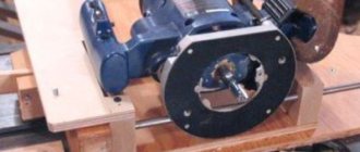
Bobbin centering.
The small dimensions of the machine and the location in close proximity of the winding reel and the feed reel with wire required the introduction of an additional mechanism for centering the feed reel.
Figure 4, 5.
Centering mechanism.
When winding the coil, the wire from the reel acts on the shutter “5”, made in the form of a “fork” and the stepper motor “3”, through a gearbox with division 6 and a toothed belt, along roller guides “4”, automatically moves the reel in the desired direction. Thus, the wire is always in the center, see Fig. 4, Fig. 5:
Figure 6.
Sensors, rear view.
Composition and design of sensors.
19. Optical sensors for the bobbin centering mechanism. 5. A curtain covering the sensors of the reel centering mechanism. 20. Curtains covering the positioner direction switching sensors. 21. Optical sensors for switching the direction of the positioner.
Positioner.
Curtains “20” fig. 6 — the winding limit is set. The stepper motor moves the stacker mechanism until the curtain blocks one of the sensors “21” fig. 6, after which the laying direction changes. You can change the laying direction at any time using buttons “1” fig. 7.
Figure 7.
Stacker.
Rotation speed of stepper motor “9” fig. 7, synchronized using sensor “10”, “11” Fig. 8, with the rotation of the wound coil and depends on the diameter of the wire set in the menu. The diameter of the wire can be set to 0.02 - 0.4mm. Using knob “8” fig. 7, you can move the entire positioner to the side without changing the winding boundaries. In this way, it is possible to wind another section in multi-section frames.
Figure 8.
Optosensor.
Composition of the positioner and opto-sensor (Fig. 7-8).
1. Buttons for manually switching the laying direction. 2. LEDs for laying direction. 3. Curtains covering the positioner direction switching sensors. 4. Linear bearing. 5. Caprolon nut. 6. Lead screw. Diameter 8mm, thread pitch 1.25mm. 7. Ball furniture guides. 8. Handle for moving the positioner to another section when winding sectional windings. 9. Stepper motor. 10. Optical timing sensor. 11. Disk covering the synchronization sensor. 18 slots.
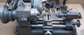
Receiving node.
Figure 9.
Receiving node.
Figure 10, 11.
Receiving unit.
1. Turn counter. 2. Commutator high-speed motor. 3. Reducer gear. 4. “Counter reset” button. 5. Speed adjustment. 6. “Start winding” switch. 7. Fastening of the winding reel.
The rotation of the wound coil is produced by a high-speed commutator motor through a gearbox. The gearbox consists of three gears with a total pitch of 18. This provides the necessary torque at low speeds. The motor speed is adjusted by changing the supply voltage.
Figure 12, 13.
Fastening a frame with a hole.
The design of the receiving unit allows you to fasten both frames with a central hole and frames without such holes, which is clearly visible in the figures.
Figure 14, 15.
Fastening a frame without a hole.
Electrical diagram.
Figure 16.
Electrical circuit of the winding machine.
All processes of the machine are controlled by a PIC16F877 microcontroller. Indication of the number of turns and diameter of the wire is displayed on a four-digit LED indicator. When the “D” button is pressed, the diameter of the wire is displayed; when pressed, the number of turns is displayed. To change the wire diameter, press the “D” button and use the “+”, “-” buttons to change the value. The set value is automatically saved in the EEPROM. Button “Zerro” - resets the counter. The “ISCP” connector is used for programming the microcontroller.
PS There are no drawings of the mechanical part, because the device was manufactured in one copy, and the design was formed during the assembly process. In this design, disassembled elements and assemblies (not marked) from VCRs and printers were used. In no case do I insist on the exact repetition of this design, but only on the use of any nodes from it in my designs. Reproduction of this device is possible by experienced radio amateurs who have skills in working with mechanics and are able to change the design to suit their existing mechanical parts. The mechanical part, accordingly, can be implemented differently. Gearboxes on engines may have a different division.
Critical elements:
For the program to work correctly, a number of conditions must be met, namely; Optical sensor “17” Fig. 1., may be of a different design, but must have 18 holes. The positioner screw must have a pitch of 1.25 mm - this is a standard pitch for a screw with a diameter of 8 mm. Positioner stepper motor 48 steps/revolution, 7.5 degrees/step - these are the most common motors in office equipment.
Demonstration video of the machine:
Below in the attachment (in the archive) all the necessary files and materials for assembling the winding machine are collected. If anyone has any questions regarding assembly and setup, please ask them on the forum. I will try to answer and help if possible.
I wish you all good luck in your creativity and all the best!
Archive "Winding machine."
I have long wanted to build a winding counter for a manual winding machine. I wanted to make a battery-powered device from two micro-finger batteries, consuming little energy in operating mode, and having simple push-button control - “Reset”, “On/Off”. The counter must be able to count backwards. Sometimes you have to unwind the turns, or there are unusual situations.
STM8S003F3P6 and STM8L051F3P6 were available in TSSOP-20 packages. It turned out that S003 is not suitable for my idea - it has a 3-5V power supply, and most likely the microcontroller will not work if the 3V battery is 50% discharged. Therefore, the choice fell on STM8L051F3P6. According to the datasheet, its power supply is from 1.8 to 3.6 V. It was decided to use MT-10T7 from the Russian manufacturer MELT as the display. This LCD was purchased about 7 years ago, and since then I have not found a worthy use. It was a pity to throw it away.
Let's talk about the sensor. At first I used integral Hall sensors that generate a logical signal at the output. Got it from the board of an underwater light. It turned out that they stop working even at a small number of revolutions. This made me sad. I had to reinvent my wheel. I decided to use hall sensors from the cd-rom drive motor and lm358 op-amp. The work of this idea from the 3rd century was extremely doubtful. But trying is not torture. To my surprise, the scheme worked perfectly with this diet.
The scheme couldn't be simpler. R5 - sets the current through Hall sensors U1, U2. On DA1, an amplifier with KU=50 was made. The signals from the DA1 outputs do not correspond to the logical levels of the STM8, so transistors Q1, Q2 representing the level converter are connected to its outputs. The microcontroller inputs are connected to positive through resistors, so there was no need to fence in an additional garden. I don’t even remember why there are elements C1 and C2 on the board. Obviously I was going to deal with interference. The transistors are actually bc817-40. But those in the diagram should also work. Hall sensors hw-101A (marking D).
Power to the sensor and display come from pin PB1 of the microcontroller. The load capacity is more than enough for these purposes.
R1 is a jumper. I couldn’t find a 0 ohm rating, so I installed the smallest one I had.
The maximum value for the count is 65535. The “RESET” button is used to reset the counter readings, “ON/OFF” - turns the device on/off.
The printed circuit board can be called more of a debug board.
Photo of the finished device.
The speed sensor is a fiberglass disc with a niodium magnet 5mm in diameter and 1mm thick glued to it, and a board with Hall sensors. The distance between the magnet and the sensors is about 5mm. Half of the familiar places on the display remained unused. I couldn’t think of anything smarter - how to show the supply voltage there. The contrast of the indicator is not enough, so I had to tilt the entire board at 45 degrees. In the photo, the sensor is attached with tape, then I attached it with several turns of electrical tape. The design turned out to be not very aesthetically pleasing, but that’s enough for me. The winding machine itself is nothing more than an old mechanism for rewinding film. I don’t know what manipulations it was designed to perform, but a reel of film is put on it. The indicator, battery compartment, microcontroller board are glued to a piece of PCB with hot glue.
The current consumption in the on state is 12.8 mA, in the off state it is 1.71 µA.
Software.
The code is written in the IAR Embedded Workbench IDE. The microcontroller operates from a built-in RC oscillator HSI with a frequency of 16 MHz. The number of turns is counted by the general purpose timer TIM2. It has a 16-bit counting register, and the ability to work with an encoder mode. This makes the task much easier. All you have to do is set the timer and forget about it. It will count the values by itself, and implements reverse counting capabilities. True, due to the peculiarities of operation of this mode, the values in the counter register are twice as large as the real ones.
Of course, the values from TIM2 need to be somehow extracted and displayed on the screen. This is done by the 8-bit TIM4, which generates interrupts through which this operation occurs. Interrupts come every 8ms. The processor has added polling of the “reset” button and manipulations to display information from the ADC and TIM2 on the screen.
The battery voltage is measured by the ADC. The reference voltage input is internally connected to the positive power supply of the microcontroller. You cannot select an internal source (as is done, for example, in AVR). But you can measure the voltage of this very source. The source voltage VREF is measured at the factory and written to VREFINT_Factory_CONV byte, it can be read.
So that the main program does not get bored, it looks to see if the ADC conversion is completed and, based on 16 samples, calculates the average.
Switching the circuit on/off is implemented based on an external interrupt by pressing a button. When the interrupt arrives, we change the variable and sit and wait until the button is released.
If the user wants to turn off the device, the main program stores the value of the TIM2 counter register in RAM. Makes all unused pins outputs and sets them to zero. If this is not done, I get interference. We turn off the reference voltage source VREF and the ADC and go to sleep. The most economical halt mode is used. The microcontroller will wake up by pressing the “On” button, via an external interrupt (External interrupts).
Microcontroller firmware.
This is a different story. When I bought the STM32F0 Discovery, I thought that the programmer on it could flash STM8. It turned out that it couldn’t. I didn’t want to spend money on a separate programmer, and I wasn’t impressed by the firmware capabilities via USART (and not all 8-bit family can do this).
In the work of radio amateurs and electricians, devices for winding copper wire with a diameter of 1.5 mm onto a special electric coil are useful. In an industrial setting, this process requires speed and precision. Home craftsmen can reproduce this technology. To do this you will need a homemade winding machine. It is characterized by the following signs:
- ease of creation and operation;
- possibility of using different transformers;
- availability of additional functions: counting the number of wire coils.
Winding machine operating method
A winding machine is a popular equipment with which transformer single-layer and multilayer cylindrical coils and all kinds of chokes are wound. The winding device evenly distributes the winding wire with a certain tension level. It can be manual or automatic, and works on the following principle:
- Rotation of the handle sets the winding of the wire or cable onto the coil frame. It serves as the base of the product and is put on a special shaft.
- The wire moves horizontally thanks to the guide element of the stacker.
- The number of turns is determined by special counters. In homemade designs, this role can be played by a bicycle speedometer or a magnetic reed switch sensor.
The manual device for laying wires is quite primitive, so it is rarely used in production.
A mechanically driven winding machine allows you to perform complex winding:
- private;
- toroidal;
- cross.
It operates using an electric motor that drives the intermediate shaft using a belt drive and three-speed pulleys. The friction clutch plays a big role in this. Thanks to it, the machine operates smoothly, without shocks or wire breaks. A spindle with a fixed frame, on which a coil is placed, starts the counter. The winding machine is adjusted using a screw to any width of the reel frame.
Modern models are equipped with digital equipment. They work through a specially defined program that stores information in a storage device. The value of the length and diameter of the wire allows you to accurately determine the point of intersection of the lines.
Operating principle of the machine
It is not difficult to work on the designed machine. The technological process requires certain actions:
- The upper shaft is prepared for work: the pulley is removed, the required length of the coil frame is set, and the right and left disks are installed.
- A fastener is inserted into the hole in the upper shaft, centered and the frame is clamped with a special nut.
- The required pulley for the primary winding is mounted on the feed shaft.
- A stacker is installed opposite the reel frame.
- The belt is placed on the pulleys in a ring or figure eight, depending on the type of installation.
- The metal wire is inserted under the additional shaft, placed in the groove, and secured.
- The wire tension is adjusted using clamps located at the top of the stacker.
- The wire should be wound tightly around the base of the coil.
- The numerical value “1+1” is recorded on the calculator.
- Each revolution of the shaft adds a given count.
- If the turns need to be rewinded, press “–1” on the computing device.
- When the wire reaches the opposite part of the frame, use a collet clamp to change the position of the belt.
For different thicknesses of metal wire, the pulley is correlated with the winding pitch.
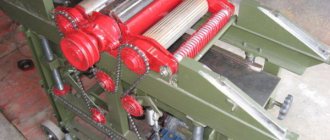
Winding machine mechanism
The winding machine is classified into groups:
- private;
- universal;
- toroidal winding.
Each product has an individual design.
A winding machine that performs row laying of wire consists of the following elements:
- The winding mechanism has the form of a welded frame, which is equipped with a motor, a toothed belt drive, a headstock and a tailstock.
- The layout mechanism allows you to move long material along the winding axis. This is a welded structure along which a carriage with guide rollers for the wire moves.
- Device models differ from each other in size and functionality.
The standard model of a device for laying wires with several bends in one turn assumes the presence of the following elements:
- The main frame, consisting of wooden or metal posts that occupy a vertical position.
- Between the supports there are two horizontal axes: one for the plates, the other for the coil.
- Replaceable gears that send rotation to the reel.
- The handle that rotates the reel axis. A collet clamp is used to secure it.
- Fasteners: nuts, screws.
Winding of wire onto toroidal cores is carried out using specialized ring-type equipment:
- The device looks like a shuttle, working on the principle of a sewing needle.
- The spool is a mechanism of two intersecting rings with a removable sector on which a toroidal frame is installed.
- The rotation of the spool is set by an electric motor.
Necessary materials and equipment for manufacturing
To make your own machine for winding wire on a round frame, you will need several parts.
The frame is made of sheet material, fastened by welding. The optimal thickness of the base is 15 mm, the side parts are 6 mm. The stability of the structure is ensured by its heaviness:
- The side parts are placed next to each other, and holes are drilled into them at the same time.
- The prepared elements are welded to the base.
- Bushings are installed in the high holes, and bearings are installed in the lower ones, which can be taken from a used disk drive.
- Fasteners on the outside of the sidewalls are securely fixed with lids.
Important components of the machine design are shafts:
- The upper shaft with a diameter of 12 mm holds the reel frame. Its role can be played by a similar structural part of a failed dot matrix printer.
- The feeder for long material rests on the middle shaft of the same diameter. It is advisable to polish it before putting it into operation.
- The lower shaft is the feed element. Its dimensions depend on the thread pitch.
The stacker sleeve has a diameter and length of 20 mm. Its internal thread matches the thread of the lower shaft.
The pulleys are three-stage, machined from steel, with a total thickness of no more than 20 mm. Otherwise, you will have to increase the shanks of the upper and lower shafts. Each block contains three grooves with different diameters, depending on the cross-section of the wire. Their width is determined by the belts. This combination provides a wide variety of wire winding steps.
Coil stacker
The wire layer is used for uniform winding, turn to turn, of the winding wire onto the frame of the transformer or coil being manufactured. The winding density depends on the speed at which the axes rotate, as well as on the diameter of the selected wire. The required ratio of rotation speed of the first and second axles can be achieved using pulleys and a belt drive. When the machine's well-functioning mechanism is operating, the stacker roller simultaneously moves with a certain pitch and the wire is laid on the frame of the winding transformer. It cannot be explained in a nutshell, but upon further reading of the article everything will become clear.
The design in question uses a factory-made M6 rod stud with a thread pitch of 1 mm. Bearings are fixed parallel to each other into the sidewalls of the winding machine bed into pre-drilled holes for them, then a pin is inserted into them. For best sliding, lubricate the bearings. A guide roller moves on the pin, through which the wire is threaded.
You can make a guide roller for laying wire yourself, having a small piece of U-shaped aluminum profile, an elongated bushing nut that matches the thread of the stud, and a feed roller with a groove in the middle.
Holes parallel to each other are drilled in the U-shaped profile. The top pair of holes is for the roller, and the bottom pair is for the extended nut. The diameter of the upper holes in the profile walls is selected along the axis on which the roller will be fixed, and the lower ones are a millimeter larger than the diameter of the stud thread. An elongated nut is tightly adjusted to fit the distance between the profile walls. This structure is then screwed onto the paver stud.
The stud is secured with nuts on the sides so that it can rotate without displacement. A spare pin is left on one side so that pulleys can be screwed onto it to mate the first and second axles.
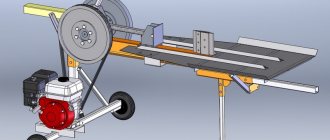
Wire laying device
Laying and winding of wire is carried out using three plates fastened together with screws with a diameter of 20 mm. A small 6 mm hole is made in the upper part, where the tension adjustment screw is inserted:
- PTFE and steel bushings with a diameter and length of 20 mm are mounted in the upper and lower parts of the inner plate.
- A leather groove up to 2 mm thick is glued between the outer elements, which is necessary for aligning and tensioning the coil wire.
- A special threaded rod or mini-clamp is mounted at the top of the stacker, which fastens the outer plates and regulates the tension. The fastening distance depends on the diameter of the wire.
- For ease of operation, the design is additionally equipped with a folding bracket for the reel.
Two pulleys are connected by a belt drive
The axles in the winding machine are connected to each other by a system of pulleys of different radii. The pulleys attached to the axles rotate using a belt drive. A belt is used as a belt.
— The stacker axis pulley is 100mm;
— A pulley on an axis with a fixed coil (winder) is equal to the thickness of the required wire, multiplied by 100.
For example, for 0.1 mm wire, we use a 10 mm pulley on the axis of the winder. For a diameter of 0.25 wire, a 25 mm pulley.
If possible, it is better to make pulleys with a pitch of 1 mm and select them during the winding process using this formula
The error depends on the accuracy of the diameter of the manufactured pulleys and the tension of the belt. If you use a stepper motor with a gear transmission as a drive in the design instead of a belt and precisely cut pulleys, then the error can be brought closer to zero.
Now I’ll tell you how to make a pulley with your own hands at home without turning to a turner. My set of pulleys is made of the same material as the bed of the winding machine. Using a compass, I marked out the required diameters of the pulleys and added a few millimeters on the larger side to machine the groove for the belt to the required size. Holes were drilled along the contour of the markings with a screwdriver and partitions were cut between them. So I collected the required number of blanks for the pulleys. I used an unnecessary “Assistant” meat grinder as a lathe.
I don’t remember exactly, I cut a thread on the meat grinder motor shaft, or it turned out to be suitable, but a pin was screwed through a long bushing nut. A blank with a slightly larger diameter than the required pulley was screwed onto the stud through nuts and washers. The meat grinder was turned on and all the irregularities were rounded to a round shape with a metal hacksaw/file, and a groove (groove) for the belt was machined with a needle file. During the process, the diameters of the homemade pulleys were periodically checked with calipers.
Manufacturing of turns counter
To determine the number of wound turns on the machine, a special counter is needed. In a homemade machine, the device is made like this:
- An electromagnet is attached to the upper shaft.
- The sealed contact is located on one of the sidewalls.
- The output contacts of the reed switch are connected to the calculator in the place where the “=” button is located.
- The coil with the wire is placed separately - on another shaft with levers that lift the device up and fold it inside the machine.
Thanks to these elements, the equipment becomes compact and does not take up much space.
Revolution counter for counting turns
One revolution is equal to one turn - this is how I used to calculate in my head when winding a transformer on a primitive device. With the advent of a full-fledged winding machine with a counter provided, it became much easier, but the most important thing is that when winding turns, the error rate was reduced to almost zero.
The winder under consideration uses a mechanical counter UGN-1 (SO-35) from Soviet equipment. It can be replaced with a bicycle meter or a mechanical counter from an old household tape recorder, where it measured tape consumption. You can also assemble a simple meter with your own hands, having only a calculator, a reed switch, two wires and a magnet.
Disassemble the calculator into two contacts closed by the “equal” button, solder two wires, and solder a reed switch to the ends of the wires. If you bring a magnet to the reed switch, its plates inside the glass flask will close and the calculator will simulate pressing a button. Using the 1+1 addition function of the calculator, you can count the revolutions.
Next, we attach the homemade disk to the first axis. We glue a magnet to the disk, and attach a reed switch to the machine body or bracket. We position the reed switch so that when the disk rotates, the magnet passes next to the reed switch and closes its contacts.
Using this principle, you can replace the reed switch with a limit switch, and make the disk in the form of an eccentric. The eccentric disk, rotating with its convex part, will press on the limit switch