Filing is the processing of metal with a cutting tool - a file, with the help of which a layer of metal is removed from the surface of the workpiece in order to give it the required dimensions, a given shape and the required accuracy (10-12 quality) and surface roughness (Ra - 1.25 ÷ 2, 5 µm). Filing is used, as a rule, after chopping or cutting to finish the surface of the workpiece and give it more accurate dimensions. Filing is also used to fit parts during assembly. In metalworking, external flat and curved surfaces, external or internal, complex shaped surfaces, recesses, holes, grooves and protrusions are subjected to filing.
Filing is divided into preliminary (roughing) and final (finishing and finishing), performed with various files. The file is selected depending on the specified processing accuracy, surface roughness and the amount of allowance left for filing.
The surfaces of various parts, which due to their size and configuration cannot be processed on metal-cutting machines or filed with ordinary files, are processed with straightening files. They also process parts made of non-ferrous metals and low-carbon steel. Using straightening files, rough marks can be easily removed.
To mechanize filing work, electric or pneumatic machines are widely used, in the chuck of which special files (boring files) or abrasive heads are mounted, as well as filing machines.
Files
Files (Fig. 1) are made from tool and carbon steel grades U13 or U13A or alloy chromium steel ШХ15.
Rice. 1. File elements: 1 - nose; 2 - rib; 3 - edge; 4 - heel; 5 - shank; 6 - handle; L - length
After cutting the teeth, the files are heat treated. The hardness and sharpness of the file teeth should ensure adhesion to a surface with a hardness of 54 HRC.
The length of a file is considered to be only the length of its cut part. Files are made with lengths from 100 to 400 mm.
The notch of files can be simple (single, Fig. 2, a), cross (double, Fig. 2, b) and rasp (Fig. 2, c).
Rice. 2. Types of notches: a - single; b - double (cross); c - rasp
Files for general use to facilitate chip crushing are made with a double notch, with the main notch located at an angle of λ=25°, and the auxiliary notch at an angle of ω=45° (Fig. 3).
Rice. 3. Files with a notch for crushing chips
The file teeth have a wedge shape with a sharpening angle β, clearance angle α, rake angle γ and cutting angle δ (Fig. 4). The rake angle γ is the angle between the front surface of the tooth and the plane passing through its top perpendicular to the axis of the file. This angle ranges from +10 to -16°.
The sharpening angle β is formed between the front and rear surfaces of the file tooth.
The clearance angle α is the angle formed between the rear surface of the tooth and the plane of the workpiece being filed.
The cutting angle δ is formed between the front surface of the tooth and the plane of the workpiece being filed.
The practice of metalworking has established the following values of file tooth angles:
- a) for files with notched teeth (Fig. 4, a): γ – negative up to -16°, β=70°, α=30°, δ=106°;
- b) for files with milled and ground teeth (Fig. 4, b): γ=2–10°, β=60–65°, α=20–25°, δ=80–88°.
Rice. 4. Geometry of file teeth: a - notched teeth; b - milled and ground teeth
Rasp cut teeth are formed by extruding the metal of the rasp blank using rasp chisels with a special sharpening shape. Each rasp tooth is offset relative to the tooth in front by half a step. This reduces the depth of the grooves formed on the surface of the sawn workpiece and facilitates the cutting process. Files with such a notch are used for filing soft materials (wood, rubber, rubber, bone, horn, etc.).
According to their purpose, files are divided into:
- general purpose locksmiths;
- rasps;
- needle files;
- machine (for filing machines);
- rotating (disk and heads);
- special.
After processing on machines and during repairs, it is necessary to file the workpieces, the planes of the frames, plates, racks, grooves, protrusions, adjust keys, chamfer, clean off burrs, nicks, etc.
Filing is divided into preliminary and final (finishing). Filing is performed with files of various purposes, sizes and shapes.
A layer of metal ranging from 0.05 to 1 mm is removed by filing. The accuracy of this type of processing (Table 1) depends primarily on the qualifications of the mechanic.
Table 1. Processing accuracy when filing with files
| Filing with files | Machining allowance, mm | Processing accuracy, mm | Roughness processed surfaces Ra, µm | |
| deviation from straightness or flatness over the entire length or surface width | average deviation from a given size | |||
| Drachevs | 0,5 — 1 | 0,15 — 0,20 | 0,2 — 0,3 | 80 — 20 |
| Personal | 0,15 — 0,3 | 0,03 — 0,06 | 0,05 — 0,1 | 10 — 2,5 |
| Velvet | 0,05 — 0,1 | 0,02 — 0,03 | 0,02 — 0,05 | 1,25 — 0,32 |
My secret
- » onclick=»window.open(this.href,» win2 return false >Print
Details Category: Long products Sawing of workpieces from long products
Using a file
remove a small
allowance
from the workpiece, thereby ensuring that the part has the exact dimensions and shape indicated in the drawing.
The main parts of a file are shown below. This is the nose
;
ribs
;
edges
;
heel
;
a ring
placed on the handle to prevent the handle from splitting.
General view of the file and profile of the notches
are shown enlarged in the figure on the left.
The profiles of the notches are: 1
–
single
,
2
–
double
,
3
–
rasp
.
Each notch
—
a file tooth
—has the shape of a wedge. Files are made from tool steel. They differ from each other in cross-sectional shape, type of notch, number of notches per unit length and length of the working part.
Depending on the shape of the surface being processed, files of one profile
(picture on the right).
So, for processing planes
Flat
are used ,
semicircular
are for spherical surfaces ,
are
used for
cylindrical holes ,
square
are for rectangular grooves and holes , and
triangular
are corners .
By size of teeth
files are distinguished between notches and their number per 10 mm of the length of the working part (see figure on the left):
garnish files
-
5-12 teeth (large notch)
;
personal
-
13-26 teeth (medium notch)
;
velvet
-
42-80 teeth (fine notch).
Files with
very coarse cuts
are called
rasps
, and those with
very fine cuts
are called
needle files
.
Drachovae
files are used only
for primary, rough surface treatment of workpieces
.
Personal
They work with files
when the main layer of metal has already been removed with a garnish file
.
For filing a personal
file,
leave a layer of metal no more than 0.2...0.4 mm.
Velvet
Using a file,
the workpiece is brought to the specified dimensions
.
Rasp
sawing
soft metals, leather, wood, rubber
.
Files
(Fig. on the right) are used for filing
small parts made of metal, plastic, and wood.
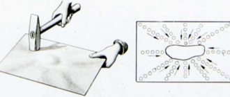
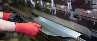
Before you start filing, you need to properly organize your workplace, and first of all, arrange the tools and workpieces on it in the most rational way. The marked workpiece is firmly clamped in a vice. In this case, the processing surface should be higher than the level of the vice jaws.
When performing filing, you need to take the correct working position (Fig. on the left): you should stand half-turned to the workbench at a distance of 150...200 mm from its front edge, your left leg is placed forward in the direction of movement of the file. The rounded part of the file handle should rest against the palm of your right hand. Four fingers are wrapped around the handle, and the thumb is placed on top and pressed against the handle. The extended fingers of the left hand are placed on the toe of the file, retreating from the edge by 20...30 mm.
During operation, the file makes reciprocating movements
:
forward
-
power stroke
,
backward
-
idle
.
During the working stroke
the tool
is pressed against the workpiece
; during
the idle stroke
,
it is driven without pressure
.
The tool must be moved strictly in a horizontal plane
.
The force of pressing on the tool depends on the position of the file (Fig. on the right). At the beginning of the working stroke, the left hand presses a little harder than the right
.
When the middle part of the file is brought to the workpiece, the pressure on the toe and the handle of the tool should be approximately the same. At the end of the working stroke, the right hand presses harder than the left
.
There are several filing methods
:
transverse
,
longitudinal, cross and
circular.
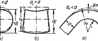
Transverse filing
(Fig. left
a
) is performed when removing large allowances.
When longitudinally filing
workpieces (Fig.
b
), the straightness of the treated surface is ensured.
It is better to combine these two filing methods: first, filing is done across, and then along. When filing with a cross stroke
(Fig.
c
), good self-control over the progress and quality of work is ensured.
First, they file with an oblique stroke from left to right, then, without interrupting work, with a straight stroke and finish filing again with an oblique stroke, but from right to left. Circular filing
(Fig.
d
) is performed in cases where frequent irregularities need to be removed from the surface being treated.
Correct filing
check with a ruler or square for clearance (Fig. on the right): if there is no clearance, the surface is flat. The durability of files largely depends on their care.
You can work with a file with a working and firmly attached handle. At the end of work, files should be cleaned of dust, sawdust, dirt, and oily substances. Files are stored so that their cuts do not touch each other. Sawdust from the surface of the product must be removed with a special brush.
Filing
– this is metalworking, during which material is removed from the surface of a part using a file.
A file
is a tool that is used for processing metals; it consists of multi-edged cutting elements; it ensures high precision of the work performed, as well as a low roughness of the processed surface of the part. The metal cutting itself is carried out with high quality and with a small error.
With the help of filing, parts are given the desired size and shape, parts are adjusted to each other, and many other works are carried out. Files are used to process metals of various shapes: curved surfaces, planes, grooves, holes of various shapes, grooves, various types of surfaces, etc. Allowances during filing are left small - from 0.55 to 0.015 mm. And the error after the work can range from 0.1 to 0.05, and in certain cases even less - up to 0.005 mm, which ensures high-quality metalworking /
A file tool is a steel bar of a certain length and profile, which has a groove on its surface. Cutting (notching) forms small and sharp teeth that determine the wedge shape in cross-section. The cross-sectional angle of a file with a cut tooth is usually 65-70 degrees, the clearance angle is from 35 to 50 degrees, and the rake angle is 16 degrees. Single-cut tools remove wide chips from the metal, along the entire cut. They are used in metalworking of soft metals. Double-cut files are used when filing cast iron, steel and other hard metals, due to the fact that cross-cutting shreds the chips, and therefore makes the work easier.
A notch with a rasp is obtained by pressing the metal with special teeth consisting of a trihedron. Machining of metals with a rasp is carried out only on soft metals and non-metallic materials. You can also get a different notch using milling. It has an arched shape and large recesses between the teeth - this ensures good surface quality and high productivity in metalworking. Files are made from U13A and U13 steel, and also from ShKh 15 chromium steel. When the teeth are cut, the files are heat treated. File handles are made of wood (maple, birch and others).
According to their purpose for cutting metal, files are divided into the following groups:
- General purpose.
- Needle files.
- Special purpose.
- Machine files.
- Rasps.
For general plumbing work, general purpose files are most often used.
According to the number of notches per 1 cm, files are divided into 6 different numbers:
- Files with cuts from number 0 to 1 (garnish) are used for coarser filing, as they consist of large teeth. When processing metals, the error ranges from 0.6-0.3 mm.
- Files with cutting No. 2-3 are used for clean filing of parts. The error in metalworking is 0.2-0.005 mm.
- Files with a cutting number of 4-5 serve as the final process. The error in this process is 0.1-0.004 mm.
The length of files is made from 150 to 400 mm.
According to their cross-sectional shape, they are divided into square, flat, round, triangular, rhombic, scissor and semicircular. For processing metals of small shapes, small-sized files are used - needle files. Processing of hard and hardened steels is carried out with special needle files, and diamond grains are fixed on steel rods. Improving productivity and working conditions in metalworking by filing is achieved through the use of mechanized (pneumatic and electric) files. Interchangeable angled and straight heads with round shaped tools facilitate filing at different angles and in hard-to-reach places. The quality of work is controlled by various kinds of tools. The quality of the sawn surface is checked with a ruler. If the plane must be sawed accurately enough, it is checked on a test plate. If you need to saw a plane at a certain angle, it is checked using a protractor or a square. To control the parallelism of two planes, a caliper is used, where the distance between the planes should be the same. If control needs to be carried out on curved surfaces, it is carried out using marking lines and special templates. Filing serves for cutting and surface treatment and differs significantly from the process of plasma metal cutting, which in turn is used to completely cut the product, as well as to process it.
4.50 /5 (90.00%) 6 votes
What is metal filing?!
Filing is the process of manually processing a surface using files. A file is a tool with a large number of notches or cuts, forming very small teeth, which are used to remove chips during the translational movement of the file (Fig. 1).
Rice. 1. File:
1 – nose; 2 – edge (wide and narrow); 3 – rib; 4 – heel; 5 – tail; 6 – handle.
File names.
Files can be divided into regular files, needle files, rasps and machine files. Files are manufactured with single-row and double-row cuts. Based on the size of the notch pitch, files with a large pitch are called bastard files, with a medium pitch - personal files, and with a small pitch - velvet files.
File shapes.
The shapes of files are: flat, blunt-nosed and sharp-nosed with a smooth or notched edge, semicircular, square triangular and round (Fig. 2).
Rice. 2. File shapes:
a – flat; b – semicircular; c – square; g – triangular; d – round; e – needle file.
In boiler production, filing is used in rare cases:
- for small craft work;
- for particularly careful fitting of parts.
Since the filing operation is very expensive and ineffective.
Storing files.
Files should be stored in a tool box, laid out in one row, with spaces between them, protected from dirt, oil, water and especially sanding dust. After work, files must be cleaned with steel brushes to remove dirt and metal particles.
How to attach a handle to a file?!
The files have wooden handles with a metal ring on the neck. To avoid cracks, the handle attachment must be done carefully. The tail of the file is gradually inserted with a rotational movement into a small hole drilled in the end of the neck of the handle. The sharpened edges of the file tail drill out the hole. At the same time, tap the head of the handle on the workbench. After some deepening, the handle is removed and the file tail is cleared of wood shavings. Then the operation is repeated until the handle fits tightly to the lower edges of the file. Sometimes, instead of drilling, they use a thin steel rod heated red-hot to burn a hole in the handle.
Filing technique.
The success and accuracy of filing depends on the correct pressure on the file and maintaining the file while working in a position parallel to the surface being filed.
Filing occurs more quickly if the pace of movement is low and the pressure on the file is high. When filing wide surfaces, the work is easier and more correct, since the plane itself is a good guide.
Purpose, application, sequence of operations. Filing is the process of processing the surface of a product with a cutting tool - a file, with the help of which a layer of metal is removed from the product being processed. Filing is carried out after chopping or cutting operations to finish the surface of the workpiece and give it more accurate dimensions. In pilot or individual production, filing is also used to fit parts during assembly.
When performing plumbing work, the main types of filing work are: filing of external flat and curved surfaces; filing of external and internal corners, as well as complex or shaped surfaces; filing recesses and holes, grooves and protrusions, fitting them to each other.
Filing is divided into preliminary rough and final (finishing and finishing), performed with various files. The file is selected depending on the specified processing accuracy and the allowance left for filing.
Tools and accessories for filing. Files are cutting tools in the form of hardened steel bars of various profiles with teeth cut on the working surfaces, which cut thin layers of metal in the form of chips. Files come with different cut lengths. The notching of files is performed single (simple) and double (cross). Files with a single cut, applied at an angle of 70-80° to the edge of the file, cut metal with wide chips equal to the entire length of the tooth, so working with them requires a lot of effort. These files are used to file soft metals (copper, bronze, brass, babbitt, aluminum). In double-cut files, one cut is called the main or bottom cut, and the other is called the top cut. The cross notch crushes the chips, which makes the work of the mechanic easier. For cross-cut files, the bottom cut is usually made at an angle of 55°, and the top cut at an angle of 70°. Step, i.e. The distance between two adjacent teeth is greater at the bottom notch than at the top. As a result, the teeth are located one after another in a straight line, making an angle with the axis of the file, and when the file moves, the tooth marks partially overlap each other. Thanks to this, there are no deep grooves left on the treated surface, and it turns out clean and smooth.
The teeth are cut on notching machines with a special chisel or obtained by milling, grinding, or drawing. Each method gives its own tooth profile. The following file tooth angles are set:
- for files with cut teeth, cutting angle δ = 106°, clearance angle α = 36°, sharpening angle β = 70°, negative clearance angle γ - up to 16°;
- for files with milled and ground teeth δ = 80-88°, α = 20-25°, β = 60-63°, γ = 2-10°.
Files are divided into ordinary, special, rasps and needle files.
Common files include flat (blunt and pointed), square, triangular, semicircular and round.
Special files include: hacksaw, rhombic (xiphoid), flat with oval ribs, oval, as well as whetstone files, etc.; in the form of round discs with notches applied around the circumference and on the sides.
Rasps are files with a special type of notch - rasp. They are divided into flat blunt-nosed, flat pointed-nosed, semicircular, round.
Needle files (small files) are divided into flat, blunt, flat, pointed, triangular, square, semicircular, round, oval, rhombic, hacksaw.
According to the number of notches per 1 cm of length, files are divided into six classes:
- 1st class - pucker files (large notch), used for rough rough filing;
- 2nd class - personal files (fine notches), used for finishing surfaces;
- 3rd, 4th, 5th and 6th classes - velvet files with fine and very fine notches, used for fitting parts.
Sawing open and closed flat surfaces at right, acute and obtuse angles. When filing, the product is clamped in a vice so that the surface being processed protrudes above the jaws of the vice to a height of 5-10 mm. The clamp is made between the mouthpieces. When filing, you need to stand in front of the vice on the left or right (depending on need), turning 45° to the axis of the vice. The left leg is pushed forward in the direction of movement of the file, the right leg is moved 20-30 cm away from the left so that the middle of its foot is opposite the heel of the left leg. The file is taken in the right hand by the handle, resting its head against the palm; The thumb is placed lengthwise on the handle, and the other fingers support the handle from below.
Having placed the file on the object being processed, place your left hand with the palm across the file at a distance of 20-30 mm from its end. In this case, the fingers should be bent, not tucked, so as not to be injured by the sharp edges of the workpiece. The elbow of the left hand is raised. The right arm from the elbow to the hand should form a straight line with the file. The file is moved with both hands forward (away from you) and back (toward you) smoothly along its entire length. As the file moves forward, it is pressed with your hands, but not equally. As he moves forward, the pressure of the right hand is increased and the pressure of the left is weakened. When moving the file back, do not press it. It is recommended to make 40 to 60 double file strokes per minute.
When filing planes, the file is moved not only forward, but also to the right or left in order to file off an even layer of metal from the entire plane. The quality of filing depends on the ability to regulate the force of pressure on the file, which is achieved only in the process of practical filing work. When the file is pressed with constant force at the beginning of the working stroke, it is deflected with the handle downwards, and at the end of the working stroke - with the front end downwards. With this kind of work, the edges of the surface being processed will be at different heights.
Filing is a metalworking operation in which layers of material are removed from the surface of a workpiece using a file.
A file is a multi-edged cutting tool that provides relatively high accuracy and low roughness of the processed surface of the workpiece (part).
By filing, parts are given the required shape and size, parts are adjusted to each other during assembly, and other work is performed. Files are used to process planes, curved surfaces, grooves, grooves, holes of various shapes, surfaces located at different angles, etc.
Allowances for filing are left small - from 0.5 to 0.025 mm. The processing error can be from 0.2 to 0.05 mm and in some cases up to 0.005 mm.
A file is a steel bar of a certain profile and length, on the surface of which there is a notch (cut). The notch forms small and sharply sharpened teeth, having a wedge shape in cross-section. For cut-tooth files, the tip angle is usually 70°, the rake angle is up to 16°, and the clearance angle is from 32 to 40°.
Single cut files remove wide chips along the entire length of the cut. They are used for filing soft metals.
Files with double notches are used when filing steel, cast iron and other hard materials, since the cross notch crushes the chips, making the work easier.
A rasp cut is obtained by pressing the metal with special triangular chisels. The spacious recesses obtained during the formation of the teeth contribute to better placement of chips. Rasps are used to process very soft metals and non-metallic materials.
The arc cut is obtained by milling. It has an arched shape and large cavities between the teeth, which ensures high productivity and good quality of processed surfaces.
Files are made from steel U13 or U13A, as well as from chromium steel ШХ15 and 13Х. After cutting the teeth, the files are subjected to heat treatment.
File handles are usually made from wood (birch, maple, ash and other species).
According to their purpose, files are divided into the following groups: general purpose, special purpose, needle files, rasps, machine files. For general metalworking work, general purpose files are used.
Based on the number of notches per 1 cm of length, files are divided into 6 numbers.
Files with notches No. 0 and 1 (garnish) have the largest teeth and are used for rough (rough) filing with an error of 0.5-0.2 mm.
Files with notches No. 2 and 3 (personal) are used for fine filing of parts with an error of 0.15-0.02 mm.
Files with cuts No. 4 and 5 (velvet) are used for final precision finishing of products. The processing error is 0.01-0.005 mm.
The length of files can be made from 100 to 400 mm. According to the cross-sectional shape, they are divided into flat, square, triangular, round, semicircular, rhombic and hacksaw.
Small-sized files called needle files are used for processing small parts. They are produced in five numbers with the number of notches per 1 cm of length from 20 to 112.
Processing of hardened steel and hard alloys is carried out with special needle files, on the steel rod of which grains of artificial diamond are fixed.
File selection
The size of the file cut is selected depending on the thickness of the layer being removed, the required surface cleanliness and processing accuracy. When choosing general purpose machinist's files, you can use the information below as a guide.
Rasp-cut files are used for processing wood, leather, rubber, rubber, bone, etc. Rasps are used to saw through babbitts, lead, zinc and other materials. They are divided into two classes. Rasps with finer cuts can be used for finishing (where high quality surface finish is not required).
Single-cut files are used for processing soft metals (brass, zinc, babbitt, lead, etc.), as well as for processing wood.
Double cut files are used for machining steel and cast iron.
It is not recommended to file soft metals with personal or velvet files, as their teeth quickly become clogged with shavings and stop cutting.
Velvet ones with fine and very fine notches are used for fitting parts, finishing, finishing and grinding surfaces.
Velvet files provide a high level of cleanliness to the treated surface. After them, no strokes visible to the eye or perceptible by hand remain on the surface.
Wood and personal files of the standard type , i.e. with the angle of the main (lower) notch λ=25° and auxiliary (upper) ω=45° (Fig. 1, d), should be used for processing steel of medium hardness, as well as in cases where it is necessary to file parts from different materials.
Brushed files are used for rough filing when it is necessary to remove a large layer of metal (up to 1 mm). In one working stroke, you can remove a layer with a thickness of 0.08–0.15 mm using a hog file.
Personal files are used for precise processing with removal of a metal layer of no more than 0.1 mm. In one working stroke, such files remove a layer of metal up to 0.03 mm thick.
Lumber files are made of the same class (basic files with a very coarse notch for the coarsest filing).
The files are divided into six numbers. The first number has 25 notches, the sixth - 80 notches per 1 cm of length. They are used when filing very precise and small products, as well as places that are inaccessible to ordinary files, in the manufacture of tools and when processing stamps.
Mechanization of filing works
Manual filing is a very labor-intensive and tedious operation, so it is increasingly being replaced by more productive methods, such as mechanized filing using electric and pneumatic filing machines, as well as filing machines.
A mechanical file is used for filing flat surfaces.
(Fig. 8.33).
In this file, when the tip 1
3
rotates , imparting a reciprocating movement to the plunger
2,
to which the file is attached.
Rice. 8.33.
Mechanical file:
1
- tip;
2
- plunger;
3 -
eccentric
Mechanized filing machines
with rotating machine files used for processing shaped surfaces of parts.
A universal filing and grinding machine with a flexible shaft and a filing head, powered by an electric motor 1
(Fig. 8.34,
a),
has a spindle to which a flexible shaft
2
with a holder
3
for securing the working tool. The machine has replaceable straight and angular heads that allow you to produce
Rice. 8.34.
Universal filing and grinding machine:
a
- general view;
b, c
- working methods;
1
- electric motor;
2
- flexible shaft;
3
- holder
filing in hard-to-reach places and at different angles. Filing techniques using this machine are shown in Fig. 8.34, b, c.
The use of filing machines increases productivity by 5-10 times.
To mechanize filing, filing machines are used,
which come in two types: reciprocating and rotary. On machines of the first type, machine files of various profiles with large and fine notches are used.
Stationary filing machine
(Fig. 8.35) has a frame
1
, on which a stand
4
with lower
3
and upper
5
brackets and a rod
6.
Stepped belt pulleys
2
allow you to regulate the speed of the file.
The workpiece 8
is fixed on the rotary table
9.
Setting the table to the desired angle is achieved using a screw
10.
The file shank 7 is secured with a screw
12
in the upper bracket 5, after which the bracket is lowered. At
Rice. 8.35.
Stationary filing machine:
a
- general view;
b
- operation diagram;
1
- bed;
2
— belt drive;
3
— bottom bracket;
4
- stand;
5
— upper bracket;
6
— rod;
7 — file shank; 8
- workpiece;
9
— rotary table;
10, 12
— screws;
11
- pedal
In this case, the lower end of the file should fit into the tapered recess of the bottom bracket 3.
When processing parts that do not require high precision, a stationary filing machine is used. It increases labor productivity by 4-5 times compared to manual processing.
Machines with rotary tool movement
Particularly convenient for making parts for stamps, molds, etc. They are stationary and portable.
In Fig. 8.36 shows a filing machine with an endless belt.
Inside the base 5 there are
Rice. 8.36.
Filing machine with endless belt:
1
- upper bracket;
2
- lamp;
3
- endless tape;
4
- table;
5
- base;
6
- power button for the electric motor, gearbox and sawdust belt drive pulley, and the tension pulley is placed in the upper bracket
1.
The sawdust endless belt has a width of 6 to 12 mm and moves at a speed of 25.54 m/s.
To file the surface, the part is placed on the table and pressed against tape 3.
The machine is turned on with button
6.
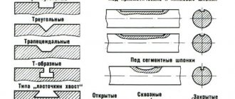
Selecting the cross-sectional shape of the file
The cross-sectional shape of the file is selected depending on the type, size and location of the surface being processed in accordance with its purpose.
The cross-sectional shape of the file is selected according to the outline of the surface being processed (Table 2).
Table 2. File cross-sectional shape and its purpose
| Types of files | Purpose |
| Flat and flat sharp-nosed blades are designed for filing easily accessible flat and convex surfaces, sawing splines and grooves (size h and larger), sawing rectangular holes | |
| Square (tetrahedral) are designed for sawing square and rectangular holes (size b and larger), narrow flat surfaces that are inaccessible for work with a wide flat file | |
| Triangular and rhombic are designed for filing internal sharp corners, triangular holes and planes (sizes b, h and larger), in places inaccessible to a flat file | |
| Round and semicircular are intended for sawing round or oval holes, concave and flat surfaces (sizes d, b, h and larger), for filing with the flat side of planes, with the semicircular side of concave surfaces (semicircular recesses) | |
| Hacksaws are designed for filing internal corners, wedge-shaped grooves, narrow grooves, planes in triangular, square and rectangular holes (sizes b, h and larger) |
Handle sizes and shapes
The correct size and shape of the handles are important for convenience, high productivity and safety when working with a file. The length of the handle should be approximately 1.5 times longer than the shank. The file shank enters the handle to a depth of 2/3 to 3/4 of its length.
When placing the handle on the file shank, a distance of 10–20 mm is left between the shoulders of the heel and the ends of the handle, which is necessary in order to seat the file into the handle for a more durable fastening.
Handles for files are made from hard wood: birch, maple, beech, ash. The surface of the handles is made smooth and smoothly polished. To prevent the handle from splitting when the file settles and during operation, a steel ring is put on its end. The hole for the file shank is drilled or burned.
When inserting a file, its shank is inserted into the hole of the handle and with the right hand, with vertical strokes, hit the head of the handle on the workbench (Fig. 5, a) or, inserting the shank into the hole of the handle, lightly hit the head of the handle with a hammer (Fig. 5, b). To remove the file, take the handle in your left hand and apply two or three weak blows with a hammer to the upper edge of the ring (Fig. 5, c).
Rice. 5. Attaching and removing the file handle
Filing techniques
The highest labor productivity during filing is ensured when the upper surface of the vise jaws is located at the level of the worker’s elbow (Fig. 6, a). The position of the worker's legs and body during work has a significant impact on filing performance.
The most convenient position is one in which the mechanic’s body is approximately 45° with a line passing through the jaws of the vice (Fig. 6, b). The left leg of the mechanic should be pushed forward with the toe in the direction of the working movement of the file at a distance of 150–200 mm from the front edge of the workbench and should bear almost the entire weight of the body. The right leg should be 200–300 mm away from the left. The angle between the midlines of the feet should be approximately 60–70° and the right leg should be a support (Fig. 6, c).
Rice. 6. Filing techniques
To remove thick layers of metal with a file, you have to press the file with greater force, and therefore the right leg is moved 500–700 mm away from the left, since in this case the load on it is greater than in the first case. When there is light pressure on the file, for example when finishing or finishing the surface of a part, the legs are placed almost side by side.
It is essential to coordinate the movements of the mechanic and the forces applied to the file (Fig. 7).
Rice. 7. Scheme of distribution of hand pressure forces during filing
The movement of the file must be strictly horizontal, therefore the vertical forces on the handle and nose of the file must vary depending on the position of the point of contact of the file with the workpiece. During the working movement of the file, the force of the left hand must be gradually reduced. By adjusting the pressure on the file, one achieves a smooth filing surface without blockages at the edges. It is necessary to press the file against the workpiece only during the working stroke (from yourself). During the return stroke, the file should only slide along the surface. The rougher the processing, the greater the force during the working stroke.
If a flat surface is filed especially carefully, it is checked for paint. The painted areas are filed down, and then the surface is again checked for paint. This is continued until the required precision of surface treatment is achieved.
The correct hand position for rough filing is shown in Fig. 8. The rate of movement of the file depends on its size and the work being performed. Filing goes faster if the pace of movement is slow and large chips are removed.
Rice. 8. Techniques for working with a file: a - position of the file handle in the right hand; b - performing filing; c — position of the left hand on the file; d - position of the left hand during finishing filing
When finishing filing, the vertical force of pressing on the file should be significantly less than during rough filing. In this case, with the left hand, press on the nose of the file not with the palm, but only with the thumb (Fig. 8, d). On the surface of the workpiece, the file leaves marks of teeth, which are called strokes or marks. The quality of filing is determined by the uniformity of the strokes. To reduce the depth of strokes and better align the planes, change the position of the hands and periodically change the direction of filing, resulting in a cross stroke.
When filing metals (especially viscous ones), chips accumulate between the teeth of the files, which interfere with further work and scratch the surface of the workpiece. Therefore, files are periodically cleaned with brushes.
To prevent scratching, the working surface of a personal file is covered with chalk. Chalk fills the space between the teeth of the file, and chips do not fall into the depressions between the notches.
Filing the surface usually ends with its finishing. In metalworking, surfaces are finished with personal and velvet files, paper or linen abrasive sandpaper, which is wrapped around the file, and abrasive whetstones. In this case, the direction of movement of the file can be transverse, longitudinal or circular strokes (Fig. 9).
Rice. 9. Finishing the surface with a file: a - with a transverse stroke; b and c - with a longitudinal stroke; g - with a circular stroke
To obtain a smooth and clean surface, the file cutter must be cleaned and rubbed with chalk more often during work (when filing aluminum - with stearin).
After finishing, the surface is treated with abrasive bars or abrasive sandpaper (small numbers) dry or with oil (Fig. 10). In the first case, a shiny metal surface is obtained, in the second - a semi-matte one. When finishing copper and aluminum, the skin is rubbed with stearin.
Rice. 10. Finishing of sawn surfaces: a – with a wooden block with sandpaper glued on; b – abrasive paper sandpaper stretched over a file; c - concave surface with abrasive sandpaper
Power tool
To increase labor productivity when performing some types of filing work, mechanized tools are used.
There are two types of devices for mechanical filing:
- th type - rotary action, using a flexible shaft or pneumatic and electric machines;
- th type - reciprocating action, using mechanisms that convert rotational motion into rectilinear reciprocating motion.
The devices of the first type are shaped rotating files (Fig. 11) and abrasive wheels.
Rice. 11. Rotating files (boring files)
Filing is greatly facilitated and accelerated by portable pneumatic filing machines, which have replaceable clamping chucks for installing rotating files and abrasive wheels of various shapes and sizes. The exhaust air of the pneumatic drive is directed in the form of a jet onto the surface of the product, thereby removing chips from the processing zone.
Devices of the second type use the drive energy of the flexible shaft of a drill or pneumatic machine. (Fig. 12). The device consists of a housing, inside which the rotational movement of the shaft is converted into a reciprocating movement of the file and has replaceable clamping chucks for installing files of different shapes and sizes.
Rice. 12. Portable pneumatic filing machine with file
The operation of a mechanical file requires some effort, but much less than with manual filing, since the worker here only guides the file and regulates the pressure. The hardest part of the chip removal work is done by the machine. Instead of a file, you can install a hacksaw blade. The exhaust air of the pneumatic drive is directed in the form of a jet onto the surface of the product, thereby removing chips from the processing zone.
§ 5. Mechanization of filing work
Sawing with a hand file is a labor-intensive and difficult operation, therefore, to increase processing accuracy and labor productivity, as well as to facilitate labor-intensive work, factories use electric filing machines, electric grinders with rigid and flexible shafts, as well as various pneumatic grinders and manual machines.
Two types of filing machines are used: with reciprocating motion and rotary motion, most often with a flexible shaft (OZS type machines). On machines of the first type, files of various profiles with large and fine notches are used.
In filing machines, special diamond tools are used to process hardened parts (dies, etc.).
Machines with flexible shafts and rotating files are especially useful for making stamps, molds, metal models, etc.
Filing machines are either stationary or portable.
A stationary filing machine (Fig. 146) has a frame 1, on which a stand 4 is fixed with lower 3, upper 5 brackets and a rod 6. A stepped pulley (closed with a casing) 2 allows you to regulate the speed of movement of the file. The workpiece 8 is fixed on the rotary table 9. Setting the table to the desired angle is achieved using screw 10.
Rice. 146. Filing machine
The file 7 is fixed in the upper bracket 5, after which the upper bracket is lowered, while the lower end of the file should enter the conical recess of the lower bracket 3. The correct installation of the file between the upper and lower brackets is checked with a square. The file is installed in a vertical position using the screws located in the upper bracket. The machine is started and stopped by pressing pedal 11.
When processing parts that do not require high precision, these machines provide a 4-5 times increase in labor productivity compared to manual processing. They can process parts of various shapes (round, triangular, square, etc.), as well as surfaces located at different angles.
Stationary filing machines do not allow processing in hard-to-reach places. In this case, portable electric and pneumatic machines are used.
The electric file designed by D.I. Sudakovich (Fig. 147) is intended for performing various plumbing and assembly works. File stroke length 12 mm, number of double strokes per minute 1500, electric motor power 120 W, operating voltage 127 and 220 V.
Rice. 147. Electric file
The file works as follows. By pressing button 7, the electric motor 6 is turned on. The rotation of the electric motor rotor through a gear pair 5 is transmitted to the crankshaft 4, on the crank pin of which a connecting rod 3 is mounted. When the shaft rotates, the connecting rod receives a reciprocating motion, which is transmitted through the rod to the file 1, fixed in the cartridge 2.
A special feature of this electric file is that its drive mechanism is made with two connecting rods, one of which is pivotally connected through a rod to the file, and the other to a balancer, and the crank of the crankshaft of the drive is located in such a way that the translational movement of the file in one direction corresponds to the movement of the balancer in the opposite direction. Thanks to this device, mutual cancellation of inertial forces caused by the reciprocating movement of the file and the balancer is achieved and the vibration of the tool body is eliminated during its operation.
The use of an electric file increases labor productivity by approximately five times compared to work performed with a conventional hand file.
The pneumatic file has a rotary type engine, powered by compressed air supplied under a pressure of 5-6 at.
The pneumatic file consists of a working tool 1 (Fig. 148), a head for securing it 2, a motion converter 3, a gearbox 4 and a motor 5. The file stroke length is 12 mm, the number of double strokes per minute is 1500. The use of a pneumatic file increases filing productivity by 2 -3 times.