Brief description of the main components of the 1K62 lathe
Headstock
The headstock serves to communicate to the spindle various rotation speeds when cutting, drilling, threading and drives replaceable tilt gears. The headstock mechanism allows:
- a) cut threads with an increased pitch of 4 and 16 times, the gear ratio between the feed chain and the spindle increases by 8 and 32 times;
- b) cut right-hand and left-hand threads;
- c) cut multi-start threads divided into 2, 3, 4, 5, 6, 10, 12, 15, 20, 30 and 60 starts.
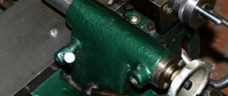
The headstock is installed on the center line in a horizontal plane with two set screws and two locking screws 1 (Fig. 5).
The spindle speed is set by two handles 5 and 9 (see Fig. 3). By turning the handle 9, which, through a mechanism with a lantern gear and the shift fork, moves the gear blocks 17-18, 19-20 and 24-25 (see Fig. 4), the required number of revolutions is selected according to table 6, placed under the handle. By rotating handle 5, which, using a flat copier with a closed curve, a lever mechanism and shift forks, moves gear blocks 9-10 and 11-12-13, the required number of spindle revolutions is set from the range selected by handle 9. When setting a number of revolutions 630 —2000 handle 9 must be tilted forward away from you and then turned to the left. The switching device allows you to obtain 23 different speeds of forward rotation of the spindle and 12 speeds of reverse rotation.
The friction clutch, as well as the main drive band brake, is turned on and off using handles 28 and 37 (Fig. 3). When you turn on the forward rotation of the spindle, one of the handles should be raised up, when you turn on the reverse one, lower it down. When handles 28 and 37 return to the middle position, the band brake is activated.
Gearbox
The feed box mechanism allows, through a lead screw with a pitch of 12 mm (without a pitch increasing link), to obtain the following threads:
- a) metric in increments from 0.87 to 12 mm;
- b) inch from 2 to 24 threads per 1″;
- c) modular from 0.5 to 3 modules;
- d) pitches from 1 to 96 pitches.
Using the mechanism for increasing the pitch, at spindle speeds from 12.5 to 40, it is possible to obtain threads with an increased pitch, 32 times larger than normal, and at speeds from 50 to 160, 8 times in accordance with the data in the table on handle 38 (see Fig. Fig. 3).
Through the running roller, the caliper at any number of spindle revolutions receives longitudinal feeds from 0.07 to 2.08 mm/rev and transverse feeds from 0.035 to 1.04 mm/rev, and at speeds from 50 to 630 per minute - longitudinal feeds from 2 .28 to 4.16 mm/rev and transverse from 1.14 to 2.08 mm/rev.
To cut more precise threads in the feed box, handle position 2 is provided (Fig. 3), in which the lead screw is engaged directly, bypassing the feed box mechanism. In this case, the required pitch is selected using interchangeable gears of a special set.
By turning handle 38, the choice of a number of threads or feeds is determined. To obtain the required value from the selected row of threads or feed, it is necessary to pull the drum disk out of the handle towards you, turn until the marks of the disk coincide with the corresponding column of the drum table, and then move the disk forward to its previous position.
To carry out rapid movements of the caliper, an overrunning clutch is mounted in the feed box on the output shaft.
Apron
The apron has four cam clutches, allowing for forward and reverse movement of the carriage and support. The movements of the carriage and the lower part of the support are controlled by the mnemonic handle 16 (see Fig. 3). The direction in which the handle is turned on coincides with the direction in which the caliper moves. The inclusion of fast movements of the caliper in the indicated four directions is carried out by additionally pressing the button 15, built into the handle 16. This pressing turns on the high-speed electric motor, which, through a V-belt drive, communicates movement to the drive shaft.
The apron has a blocking device that prevents the simultaneous activation of the longitudinal and transverse feeds of the caliper, and the simultaneous activation of the lead screw and the lead roller. as well as a safety cam clutch, which is activated under the influence of forces generated when the apron is overloaded.
To cut a thread, use handle 31 to turn on the lead screw nut and disengage the rack and pinion gear by pulling button 35 toward you.
Specifications
All full technical specifications are placed in the passport that comes with the product. For the purpose of general familiarization with the main capabilities of our sample, we present a brief overview of the parameters.
- The largest diameter of the workpiece: 400 mm - above the bed, 220 mm - above the support.
- Limit weights of processed workpieces: the largest weight of the part installed in the chuck is 300 kg, on the centers - 1.3 tons.
- The machine was produced in three dimensional modifications : center-to-center distances of 710, 1000 and 1400 mm. Accordingly, the maximum distance of longitudinal movement of the caliper (which means the length of the workpiece) is 640, 930 and 1330 mm.
- The largest recommended diameter of the workpiece passing through the intra-spindle hole is 45 mm (the hole itself is 47 mm).
- The size of the seat cone in the spindle is Morse No. 6, and in the tailstock quill it is Morse No. 5.
- The maximum distance to which the tailstock quill can be extended is 200 mm.
- The height of the tool holder installed in the tool holder is 25 mm.
- Overall dimensions of the machine with a center distance of 1000 mm: length - 2812 mm, width - 1166 mm and height - 1324 mm.
- The weight of the 1K62 machine with the same distance between centers is 2140 kg.
- Cutting metric threads with pitch ranging from 1 to 192 mm.
- Cutting inch threads with thread pitch from 2 to 24 threads per 1 inch.
- Making modular threads with pitches ranging from 0.5 to 40 modules.
- Carrying out pitch threads with pitches ranging from 1 to 96 pitches.
- The spindle speed limits are from 12.5 to 2000 rpm.
- The limits of longitudinal feeds of the caliper are from 0.07 to 4.16 mm/rev., transverse feeds are from 0.035 to 2.08 mm/rev.
According to the passport and technical characteristics, 1K62 is equipped with four electric motors:
- main drive motor 10 kW;
- fast movement motor with a power of 0.8 kW;
- hydraulic station engine with a power of 1.1 kW;
- cooling pump motor with 0.125 kW power.
Some models of metalworking equipment are designed with a power circuit powered from 220 V. But this is not the rule, but an exception concerning small “home” samples. The unit we are considering, both in the basic configuration and in modifications, requires a power supply of 380 V.
Kinematic diagram of the 1V62G machine
The kinematics of the 1V62G screw-cutting lathe makes it possible to set into motion both the main drive (spindle rotation, support feed) and auxiliary ones: accelerated support approach, speed reverse, and others. Spindle rotation is achieved by V-belt transmission from motor 1 through pulleys 2 and 3 to the spindle pulley, then the spindle rotates through the gearbox gears. The caliper moves through shaft 12 from the feed box and is synchronously connected to the gearbox through a series of gears and intermediate shafts.
Kinematic diagram of the 16v20 machine
In the left cabinet of the bed there is an oil reservoir in which an oil pump is built in to supply oil to the machine components. The right cabinet contains a pump for water, which drains and collects in the lower niche of the machine. It also serves as the basis for installing the bed. The engine for transmitting the accelerated movement of the caliper is mounted on the side of it using brackets. The caliper moves through the running shaft 5 and screw 4, and they are covered with casings 1 and 14. When processing parts above the cavity, it is possible to move the upper carriage in the desired direction. Before you start processing a workpiece with a diameter of 445 mm, you need to remove the protective bridge (22). It is mounted on the frame guides with countersunk bolts (23) and pins (24).
When installing the adapter strip in place, you need to tighten the bolts carefully, crosswise, so that there is no distortion. Under the guide there is a rail assembled from parts, and through it the caliper moves during operation.
Under the guide there is a rail assembled from parts, and through it the caliper moves during operation.
Such machines are used in industrial and agricultural enterprises, and also, due to their relatively low weight (2430 kg), in repair shops.
Electrical circuit of the machine 1V62g
Screw-cutting lathe 1K62D (RMC 1500)
If you need to buy a screw-cutting lathe 1K62D (RMC 1500), call:
in Moscow +7 (499) 372-31-73 in St. Petersburg in Minsk +375 (17) 246-40-09 in Ekaterinburg in Novosibirsk +7 (383) 284-08-84 in Chelyabinsk +7 (351) 951 -00-26 in Tyumen +7 (3452) 514-886
in Nizhny Novgorod +7 (831) 218-06-78 in Samara in Perm in Rostov-on-Don in Voronezh +7 (473) 202-33-64 in Krasnoyarsk +7;
in Abakan, Almetyevsk, Arkhangelsk,
Astrakhan, Barnaul, Belgorod, Blagoveshchensk, Bryansk, Vladivostok, Vladimir, Volgograd, Vologda, Ivanovo, Izhevsk, Irkutsk, Yoshkar-Ola, Kazan, Kaluga, Kemerovo, Kirov, Krasnodar, Krasnoyarsk, Kurgan, Kursk, Kyzyl, Lipetsk, Magadan, Magnitogorsk, Maikop, Murmansk, Naberezhnye Chelny, Nizhnekamsk, Veliky Novgorod, Novokuznetsk, Novorossiysk, Novy Urengoy, Norilsk, Omsk, Orel, Orenburg, Penza, Perm, Petrozavodsk, Pskov, Ryazan, Saransk, Saratov, Sevastopol, Simferopol, Smolensk, Syktyvkar , Tambov, Tver, Tomsk, Tula, Ulan-Ude, Ulyanovsk, Ufa, Khabarovsk, Cheboksary, Chita, Elista, Yakutsk, Yaroslavl and other cities
Toll-free number throughout Russia.
In the CIS countries - Belarus, Turkmenistan, Uzbekistan, Ukraine, Tajikistan, Moldova, Azerbaijan, Kyrgyzstan, Armenia in the cities of Bishkek, Baku, Yerevan, Minsk, Ashgabat, Chisinau, Dushanbe, Tashkent, Kiev and others for the purchase of equipment such as screw-cutting lathe 1K62D (RMC 1500) call any convenient number listed on our website, or leave your contacts under the ORDER A CALL button at the top of the site - we will call you back.
stanok-kpo.ru
Rules of operation and care
There are rules for caring for the unit so that it does not break down and is always ready for use. The equipment must be regularly inspected and checked for damage.
Engine operation is determined by sound. After starting, listen. If there are no extraneous sounds, oil is supplied, then the engine is working. If there are extraneous sounds, you need to disassemble the mechanism and find out the reason.
Care must be taken to ensure that the safety shield is holding the workpiece. Even if there is a minor malfunction, you must stop working and take the parts for repair.
From time to time, clean pipes and equipment, change cutters so that the load on the engine is less.
Design and operating characteristics of the main components of the machine
General view and layout of the 1K62 machine (Fig. 1)
The main components of the machine: bed 13, which serves to connect all components of the machine; headstock 2, which houses the spindle 4 of the machine and the gearbox; a support 11 on which the cutting tool is fixed; tailstock 15; feed box 3, transmitting rotation to the lead shaft 24 and the lead screw 23; cabinet 20 with electrical equipment of the machine; stands 22 and 29.
The machine bed 13 (see Fig. 1, a) rests on the left 29 and right 22 pedestals, to which it is rigidly fastened. The left cabinet contains the electric motor of the main drive of the machine. The right cabinet contains a pump that supplies coolant through a hose to the cutting tool. Liquid flows from trough 27 into the internal cavity of the cabinet. The most accurate position of the moving units of the machine is ensured by the combined frame guides - prismatic a and flat b (Fig. 1, b).
Headstock 2 is bolted to the left side of the frame. The inner part of the headstock contains a spindle 4 and a gearbox, covered with a lid on top.
If necessary, a rod processed on the machine can be passed through the through hole of spindle 4, and the front center can be installed in the conical socket of the spindle. At the right protruding end of the spindle there is a centering belt, a shoulder and a thread for precise alignment and fastening of the faceplate with chuck 5, into the cams of which the workpieces are installed.
The support 11 is designed to move the cutting tools attached to it and consists of the following main parts: a carriage 6, an apron 25, a transverse slide 7, a middle rotating part 8, an upper slide 10 and a quadruple tool holder 9 for installing and securing cutting tools.
Carriage 6 moves in the longitudinal direction along prismatic a and flat b guides (Fig. 1, b). Planks 1 and 2 of the carriage slide along the lower guides d and c. The carriage is moved manually in the longitudinal direction by rotating the flywheel 26 (Fig. 1, a).
The apron 25 is rigidly fixed to the carriage 6. It contains mechanisms that convert the rotational movement of the roller 24 and the screw 23 into the translational movement of the caliper.
To eliminate backlash in the screw drive, the screw nut consists of two parts, which are moved apart with a wedge. The middle part 8, together with the guides of the upper slide 10 located on it, which can be rotated relative to the axis of the machine at an angle and mounted on the transverse slide 7, is intended for processing conical surfaces of products.
The upper slide 10 is designed to move the cutter manually when rotating the handle 12. The exact amount of movement of the caliper is manually measured using dials with a division value of 0.05 mm
Feed box 3 serves to transmit rotation to the lead roller 24 or lead screw 23. The feed box is connected to the machine spindle by a transmission, which includes a set of interchangeable wheels located under the shield 1.
The tailstock 15 is designed to support the workpieces being processed with its rear center or to install and move axial tools. The main parts of the tailstock: plate 17, body 16, quill 14, clamping bar 1 (Fig. 1, c).
The tailstock moves along prismatic a and flat b guides (Fig. 1, c) of the machine bed. The movement is carried out either manually or using a caliper - if the tailstock is connected to it with a lock (Fig. 1, d). The lock consists of a bar 2 attached to the cross slide 1, a caliper and a bar 4 connected to the tailstock plate 3. By bringing the caliper to the tailstock and moving the slide 1 in the transverse direction, the protrusion of the bar 2 is inserted behind the protrusion of the bar 4. In this case, the tailstock is connected to the caliper and together with it will move in the longitudinal direction from the feed mechanism.
In order for the top of the rear center to be accurately located on the axis of the machine, the body 16 (Fig. 1, a) is moved in the transverse direction relative to the plate 17. To process conical surfaces of parts, the rear center is shifted with a screw 19 from the axis of the machine in the direction “toward” or "Push". Quill 14 has a tapered hole for mounting rear center or axial tools.
The electrical equipment of the machine is located in cabinet 20. On the front wall of the cabinet there is a panel 18 with an ammeter indicating the current of the main electric motor of the machine, and switches that turn on the machine to the electrical network, machine lighting and the electric motor of the pump supplying coolant.
Under cover 21 there is an electric motor for rapid movement of the caliper.
1. Screw-cutting lathe model 1K62D.
TOPIC 9. KINEMATIC ADJUSTMENT OF MACHINES WITH COMPLEX FORM-GENERATING MOVEMENTS.
In this topic, we will consider issues related to the kinematic setup of machines with complex shaping movements. When performing kinematic analysis, it is necessary to use the following literature: 1. A.M. Coachman. Silent kinematic diagrams of metal-cutting machines; 2. V.I. Kalinkin. Kinematics of metal-cutting machines.
The most common machines with complex shaping movements that require adjustment of kinematic chains are:
- screw-cutting lathes;
- turning and backing;
- tooth shaping;
- gear milling
- gear cutters for cutting bevel wheels with a circular tooth;
-gear planers for cutting bevel wheels with straight teeth;
- thread milling and others.
Let us examine in more detail only the machines listed above.
When performing turning operations, this machine does not require calculating the kinematic parameters of the adjustment elements in the feed chain, such as the replacement wheels and the feed box.
When cutting threads with a cutter, additional adjustment is required depending on the type of thread.
Metric thread is specified by pitch T = t mm.
An inch thread is specified by the number of threads n per 1” (inch), and the thread pitch is determined by the formula T = 25.4n mm.
A modular thread is specified by module m, and the thread pitch is determined by the formula
T = π × m× zmm.
The parable thread is specified by the diametric pitch P, and its pitch is determined by the formula T = 25.4 ×πP
Figure 9.1 shows the kinematic structure of the thread-cutting kinematic chain. Where iУШ – step increasing link, which is located, as a rule, in the gearbox; iG – guitar of interchangeable wheels; iK – box
| feeds, t – pitch of the machine lead screw. | |
| Equation of kinematic tuning in rotation | |
| general form for thread-cutting kinematic | |
| the chain looks like | |
| 1rev.shp×c ×iУШ×iГ×iК×tХ= T | |
| Rice. 9.1 Structural diagram | When cutting threads with standard pitches - |
| turning-screw-rezeonostane | mi gear ratios of the tuning bodies |
take the following values: When cutting metric and inch threads, the gear ratio of the guitar of interchangeable wheels iГ = 4250, and when cutting mo-
muzzle and pitch threads iG = 6497; The values of iУШ and iК are determined by the design
studfiles.net
General design and operating principle
The design features regulatory bodies that are familiar to experts, and a simple control scheme is used. The model consists of nodes:
- bed;
- front, rear cabinets;
- headstock;
- chuck;
- tailstock;
- tool holder;
- apron with caliper feed mechanics;
- drive shaft;
- gearbox.
The design is designed for high vibration resistance and rigidity. The base is pedestals, and to increase their rigidity, vertical ribs are used on the walls.
On the left side of the unit there is a headstock, inside it is a gearbox, a spindle with a chuck. On the right side is the tailstock. The caliper can move in different directions due to the apron.
Design Features
The design features of 1K62 include the versatility of its functionality and well-organized workspace. The ease of setting up the operating modes of the machine is especially noted.
The increased rigidity of all its working units is ensured by the use of heavy-duty bearings in the design. Due to the significant drive power on the 1K62, it is possible to process workpieces that have undergone long-term hardening.
Please note: The design of the bed provides the ability to change the position of the rear beam, allowing you to grind cone-shaped parts. The beam itself is connected to the lower plane of the caliper with a special lock, which expands the range of drilling operations
The main structural components of this product include:
The beam itself is connected to the lower plane of the support with a special lock, which expands the range of drilling operations. The main structural components of this product include:
- A bed with two cabinets located at the edges.
- Two headstocks (front and rear placement).
- Caliper with tool holder and apron mechanism.
- Gearbox (Gearbox).
Let us next consider the organization of the workplace.
Workspace dimensions
The characteristics of the 1K62 workplace are as follows:
- the height of the frame with superstructures is one and a half meters;
- the total length of the base is from 2.5 to 3.5 meters (with a width of 1.2 meters);
- the permissible size of the part placed above the support is up to 22.4 cm, and above the bed - up to 43.5 cm
- permissible incisal section - within 2.5 cm;
- the maximum size of the blank fixed during processing is within the range from 75 cm to 150 cm;
- through size (diameter) of the shaft – 5.5 cm;
- free movement of the working carriage – up to 1330 mm.
Under certain operating conditions of machine tool equipment (when fixing a workpiece in a chuck, in particular), the weight of the processed blank can reach 300 kg. When installing workpieces in a centered position, its weight can reach 1300 kg.
Headstock and tailstock
The main purpose of the headstock is to provide the specified parameters for shaft rotation in various operating modes when performing the entire range of work operations. Switching elements for replaceable gearbox gears are also located here. The mechanisms located in it allow:
- make threads with a pitch that is a multiple of 4 and 16 units; in this case, the gear ratio increases by 8 and 32 times, respectively;
- provide right and left cutting;
- prepare threads in multi-start mode (from 2 to 60 starts).
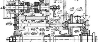
Machine diagram 1A62. Screw-cutting lathe. Kinematic
A kinematic diagram is a graphical diagram of the display of working units and blocks of a structure mechanism. The basic kinematic diagram shows the sequence of transmission of motion from the engine through the intermediate mechanism to the working parts of the product and their relationship. Kinematic diagrams specifically depict only those elements of the assembly structure that take part in the transmission of motion, these include intermediate gears, running rods and clamps, shafts, drive pulleys, couplings, etc. The design of any assembly mechanism that has moving parts is drawn in in the form of graphics on the diagram with solid lines alternating with dotted lines, respectively marking each element with numbers and subsequent decoding. There are spatial kinematic diagrams of mechanisms, which are usually depicted in the form of expanded diagrams. They are obtained by combining all axes in one plane and then projecting them onto the plane. Such diagrams make it possible to understand the sequence of motion transmission. On a kinematic diagram it is possible to display individual elements of other types of circuits that directly affect its operation, for example, electrical ones. The kinematic diagram begins to be read from the engine, which is the source of movement of all parts of the mechanism. By installing each element of the kinematic chain shown in the diagram sequentially according to the symbols, its purpose and the nature of the transmission of motion are revealed.
Machine device
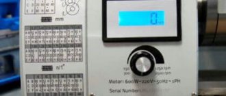
The front of the lathe, shaped like a cabinet, is actually the gearbox. On the top surface of the cabinet there is a peephole for checking the oil. If oil flows like a fountain during operation, it means that the pump is working correctly and provides lubrication to the rubbing parts.
On the front panel of the headstock there are two gear shift levers, which are located at the edges. The right lever lowers the spindle speed and has four positions: optimal speed for turning. high speed for finishing cylindrical surfaces. Intermediate position for cutting threads with a cutter or die. The left gearshift lever has six positions, respectively, six speeds.
Between the speed shift levers there are two other levers for setting the thread cutting operation. The design of the machine allows you to cut right-handed and left-handed threads.
At the bottom of the headstock there is a feed box equipped with two levers. The lever on the left switches the feed and thread type. Located on the right, it is used to adjust the feed of the caliper depending on the depth of cut and the hardness of the material being processed. The K-62 machine is equipped with two motors: main and rapid feed. The front apron is equipped with two flywheels:
- one for feeding along the bed;
- the second is for serving across.
Main nodes
The rotating spindle of the 1k62 screw-cutting lathe ensures surface treatment of cylindrical and conical workpieces.
The caliper performs the longitudinal and transverse movement of the tool holder with the cutter for removing chips, cutting threads, facing or cutting off the workpiece. The installed feed mechanism drive is used to configure thread cutting modes. By means of the screw-nut transmission, the lateral movement of the tool holder is carried out.
The machine control levers are installed on the headstock. To change cutting modes, a mechanism for switching spindle rotation speeds is installed. The direction of movement will be changed by a special friction clutch and a reversing mechanism.
The apron is used to change the feed modes, and for control there are levers on the headstock. The apron mechanism feeds the caliper during turning and threading.
The main parameter that determines the size of a lathe is the height from the plane of the bed to the axis of rotation of the spindle. This height is half the largest diameter of the part that can be machined above the bed. The largest diameter of the product above the bed and the distance between the chuck and the tailstock quill determine its capabilities and are included in the main technical characteristics of the 1k62 machine. Before work, the turner checks the dimensions of the workpiece according to the given characteristics.
The machine is equipped with an additional electric motor with a power of one kilowatt for accelerated movement of the support carriage; it is turned on by pressing a special button located at the end of the control lever. During drilling work, you can mechanically feed the tailstock with a drill by attaching it to the support.
Specifications
The weight of the K62 lathe is 2.5 tons.
Dimensions:
- length - 2500 millimeters;
- width - 1200 millimeters;
- height - 1500 millimeters.
The maximum diameter of the workpiece above the machine support is 224 millimeters. The workpiece for processing is no more than 1500 millimeters in length. Spindle speed 2420 rpm.
A screw-cutting lathe is a complex technological machine with 24 spindle rotation speeds and 48 support feeds. The controls are located on the front panels of the gearboxes and feeds.
To set a given spindle rotation speed, you must first disable the clutch and turn off the electric motor, and then move the handle to set the required frequency range (for example, 630...2000, 50...160). The gear shift knob should be moved smoothly, without jerking, ensuring that it is fixed in each of the four positions, setting the specified spindle speed (for example, 630 rpm).
1K62D. Screw-cutting lathe [DJVU] – Everything for the student
1K62D. Screw-cutting lathe [DJVU] – Everything for the student
- djvu file format
- 1.51 MB in size
- Added by user Vitaly 11/14/2011 11:52
- Edited 05/20/2017 01:28
Manual. Chelyabinsk, 1987, 105 p. Contents: General information. Basic technical data and characteristics. Main movement mechanism. Feeding mechanism. Contents of delivery. Safety instructions. Composition of the machine. Design and operation of the machine and its components. Electrical equipment. Pneumatic equipment. Lubrication system. Installation procedure. Operating procedure. Typical faults and methods for their elimination. Features of disassembly and assembly during repairs. Bearing arrangement diagram. Certificate of acceptance. Instructions for operation, maintenance and repair. Supplier's warranty obligations and consumer's responsibility.
- To download this file, register and/or log in to the site using the form above.
- Registration
www.twirpx.com
Advantages of the unit
Despite its long history, the unit we are considering is still common in metalworking plants and repair shops. The undoubted advantages of the model are due to the following criteria.
- The components and structural parts of the equipment have increased strength and increased rigidity, as well as special support parts, which allows you to work with hardened material.
- The special design of the machine allows it to better withstand vibrations during the manufacturing process of parts.
- The factory equipment includes replacement gears for advanced customization of the headstock guitar to increase the range of threads that can be cut.
- A well-thought-out power supply system for the machine, including several thermal relays and fuses to protect against short circuits and overloads.
- The presence of special support elements that compensate for excessive dynamic loads. Thanks to this, it becomes possible to produce parts with increased precision.
- Possibility of transversely shifting the tailstock by 15 mm in forward and reverse directions for turning flat cones.
- Wide range of adjustment of spindle speeds and working feeds.
- One of the main advantages of the 1K62 screw-cutting lathe and its technical characteristics is the ease and simplicity of setting operating modes, which undoubtedly makes it easier to control the machine in the production process and relieves the worker of unnecessary physical stress.
- Availability of additional equipment and accessories, included with the machine or purchased separately. It significantly expands the working functionality.
Despite the long-discontinued production of machines of this model, improved versions of machines manufactured on the basis of 1K62 continue to be produced. The wide capabilities, versatility, ease of maintenance and control of modern mechanisms are developed based on many years of experience in using the 1K62 machine in various conditions. Until now, it remains one of the best metalworking machines.
Scope of equipment
The range of applications of this unit is quite wide:
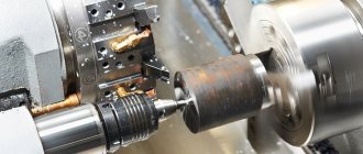
- turning of cylindrical, conical and shaped surfaces;
- drilling, boring, reaming and countersinking of holes;
- cutting external and internal threads of various types, both with taps and dies, and with thread cutters and heads;
- rolling of surfaces;
- turning of asymmetrical parts and housings using 4-jaw chucks and faceplates;
- turning thin and long parts using steady rests;
- copying work using the supplied hydrocopying device and much more.
The model we are considering is a universal screw-cutting lathe, the technical characteristics of which are quite unique. The 1K62 machine has a passport, according to which it can cut inch, pitch, modular threads and Archimedean spirals. The main thread is metric. All turning operations can be performed with a fairly wide range of steps.
Electrical equipment of the machine
Electrical diagram of the machine
Connection for further operation of the 1K62 machine is made to a three-phase power supply. A grounded or insulated neutral wire is required.
To operate the machine, a power circuit of 380 V, 50 Hz is required. In special cases, the electrical circuit can be adapted for connection to a standard 220 V network. The operation of the control circuit occurs due to the supply of 110 V electricity. The lighting unit operates from a 36/24 V network.
The operation of the equipment is carried out by 4 electric motors. The main power is 10 kW. For fast movements, a 0.8 kW power unit is used. The hydraulic station operates from a 1.1 kW electric motor. Also in the electrical circuit there is a 0.125 kW cooling pump.
In addition, the design of the 1K62 machine contains the following electrical components, described in the data sheet:
- thermal relays type RT-1;
- pump control unit;
- transformer for organizing local lighting;
- fuses;
- lighting.
Protection of electric motors from thermal overloads occurs through the installation of thermal relays. They are mounted in the electrical circuits of the main unit and pumping station.
The video describes in detail the rules for lubrication of machine components described in the passport:
Review of screw-cutting lathe 1K62
Well known to those whose occupation is related to turning and other processing of metal blanks, the 1K62 screw-cutting lathe was produced in Moscow for 15 years. Being one of the popular models, it was known throughout the Soviet Union as a device that makes it possible to create parts of a wider range of standard sizes.
The machine is designed for processing complex surfaces: cylindrical, internal, end, conical and external, and for thread cutting - using cutters, drills, reamers, taps, dies and countersinks of various shapes and sizes. The alphanumeric indicator of the 1K62 model means the following: “1” – lathe, “6” – screw-cutting lathe, “K” – generation of the machine, “2” – height of the centers.
- Advantages of the machine
- Lathe 1K62: technical characteristics
- Design features of the machine
- Other design nuances
General information about the 1K62 lathe
The alphanumeric index 1K62 is simply deciphered:
1 - machine group - turning;
K - generation of the machine;
6 - type - screw-cutting;
2 - height of centers. In this model it is 220 mm.
At the end of the marking there may be a letter indicating the accuracy class of the machine.
The biography of the 1K62 screw-cutting lathe is quite interesting. It was developed in Moscow, where it was later produced. The beginning of its use in production can be considered the thirties of the last century. True, its name then contained the abbreviation DIP (let's catch up and surpass). But after 1937, when a new machine classification system was introduced, modern markings appeared.
The production of 1K62 has long been discontinued, but a large number of these wonderful machines still continue to be used in production due to the reliability and thoughtfulness of the design. Of course, it is extremely difficult to find a completely new product; during operation, the components and parts of the units wear out and become unusable. But with proper care and maintenance, some examples differ from new only in an updated layer of paint.
Undoubtedly, some equipment falls into complete disrepair, while other machines require major repairs. If you replace the failed electrical equipment, re-grind the frames and guides or scrape them if necessary, then the updated 1K62 with unique technical characteristics will be able to serve in production for quite a long time. For this, of course, all technical documentation for the machine is necessary.