Every craftsman knows that to make a hole you need a special tool - a drill. Nowadays no home can do without this tool. Craftsmen who work with wood or stone constantly need to use a drill.
The most difficult thing in such cases is to make many holes accurately and evenly. At large factories for the manufacture of such products, there are special machines for drilling.
For a craftsman at home, such a huge device is of no use, so most often people make their own drilling machines.
In size, such a machine is much smaller and more compact than the factory one. It can easily be placed in a small garage or workshop. We will now look at how to make and design a drilling machine with our own hands.
Operating principle and main components of the drilling machine
A drilling machine is a well-structured product.
Firstly, the bed. As a rule, this is a steel plate (but for small devices it can be made of light alloy) on which the entire product is mounted. A stand is installed vertically on the edge of the bed farthest from the master. The working part, consisting of a motor, a working head with a cartridge and, if there is one, a transmission, moves up and down along it and turns left and right. The head on the stand is fixed in the required position by a locking mechanism.
And precise positioning of the height of the spindle with the chuck and drill is performed with a special handle.
Professional drilling machine
The motor and work spindle can be located on both sides of the stand. In this case, a belt drive is organized on several pairs of pulleys between the motor shaft and the working spindle. By throwing the belt from one pair to another, they set different speeds of rotation of the working body - the drill.
Drilling machine with pulleys and belt drive
Another option is to mount the cartridge on the motor shaft. The design is simpler, but the speed of rotation of the drill must be adjusted by changing the speed of rotation of the motor, and this requires an electrical or electronic circuit.
Drilling machine with chuck on motor shaft
The working tool is a drill. Drills are classified by size and purpose. In the practice of home-made workers, diameters from 0.5 mm to 12 - 18 mm are used. Drills are selected for work on wood, plastic, hard and soft metal, and concrete. They will differ in the sharpening geometry of the working end and the presence or absence of hard surfacing at the end.
Drill
The machine works this way. The motor turns the working spindle, at the lower end of which the chuck sits. There is a drill clamped in it. With rapid rotation and pressure on the surface from top to bottom, the drill cuts into the material with its cutting edges.
Drill device
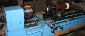
Fantasy is an indispensable condition for any creative success, but in mechanical engineering it is useless without accurate calculations and comparison with solutions proven by experience. The history of machine tool construction goes back thousands of years - foot-operated bow lathes and drilling machines were used already at the end of the Stone Age. On the topic of this article, a proven sample is an industrial-style desktop vertical drilling machine. We will refer to it when choosing and deciding how best to make a drilling machine with our own hands: there are only a few examples of drilling machines in use that are over 100 years old, and they still maintain accuracy.
The structure of a desktop vertical drilling machine is shown in the figure:
Design of a desktop vertical drilling machine
Its main modules are a bed, a column, a console and a table for a part. The components of the main nodes are slightly highlighted in color, and their components are brighter in color. The simplest table (not counting a wooden block) is a vice. The rotary-sliding table allows, in addition to drilling, to perform some milling operations. The bed is usually tightly attached to a workbench or other reliable support.
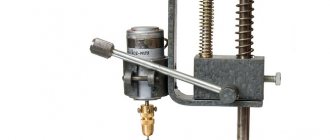
Screw clamp – clamp of the mini-drilling machine console
In operation, the console is installed in the required position in accordance with the size and configuration of the workpiece using the lifting and rotating mechanism of the slider, and is fixed. The spindle is fed into the working stroke by a separate feed mechanism. In amateur and industrial designs for home use, the lifting and turning mechanism is most often the operator’s hand, and the lock is a screw clamp of the slide, see fig. on right; According to TB, both are acceptable. But what must certainly be in the design of a drilling machine according to the requirements of the same safety regulations is a bumper device or just a bumper: if you throw the feed handle, the spindle or carriage along with it should automatically bounce up until it stops. In home drills, the chipper is most often a spring installed in a suitable place, see below.
Note: industrial production, sale and use at enterprises and workshops of individual entrepreneurs of drilling machines without a fender device are prohibited by PTB.
Scope of application of homemade drilling machines
The thought of creating a drilling machine with their own hands arises among people who love to tinker, but at the same time are not involved in the manufacture of any objects on a professional basis, either using metal or other materials (wood, plastic, etc.).
This is due to the fact that home-made equipment will not be able to fully replace industrially produced analogues in full, both in functionality and performance, but will only facilitate the performance of simple repairs and other work.
In addition, radio amateurs and people involved in the independent production of printed circuit boards can also set themselves a similar task, because Having a drilling machine greatly simplifies their work, and purchasing factory-made equipment is unprofitable.
Advantages and disadvantages of self-production
A coordinate table is an additional structure to a milling, drilling metal or woodworking machine. Thanks to it, you can increase equipment productivity by reducing the labor intensity of the parts processing process. The workpiece is simply fixed on the working surface and can move smoothly along a given path.
Homemade coordinate tables have the following advantages:
- small dimensions;
- simple design form;
- controlled mechanically;
- used in handicraft production.
Their main advantage is saving money. Making such a design from scratch will cost much less than buying a factory-made manipulator. Of course, there are a number of difficulties when making it yourself. A suitable drawing is needed, according to which the required trajectory of the workpiece will be set. If there is no someone else’s experience, then you will have to create it yourself, but any error when drawing the diagram will make itself felt during work. In addition, a homemade table is only suitable for small-scale production, since the simplest homemade mechanisms wear out much faster than factory ones.
For mass production of parts and their processing, only a factory model of a coordinate table is suitable.
Simple design form
Small dimensions
Mechanical control
Saving money
Options and techniques for creating a good drill press
In industrial plants and workshops with large volumes of repetitive procedures associated with the processing of materials, simple designs are not enough.
This is ensured by the fact that during drilling operations, materials with different densities and hardness are machined.
To assemble a high-quality and productive machine for drilling holes, you can choose different options, the most common of which include the following:
- a drilling machine made from a professional drill with a reliable and stable stand;
- equipment with an asynchronous motor and the ability to install drills of different diameters.
Vertical and horizontal drilling machines that differ in design, made by hand, allow you to work with different materials.
These can include plastic, metal and wooden parts, the processing of which requires compliance with the parameters of accuracy and quality of drilling activities.
Using both options, you can significantly save money without spending it on purchasing an expensive factory-made machine that will not be used very often.
Guides
Of particular importance in the design of the device being developed are the so-called guides - components along which the table moves in the required directions.
The better they are made, the more accurately the specialist will work on the machine, set the position of the workpiece being processed and the easier it will be to move it to the right place, apply filler materials and perform other necessary actions.
Two types of guides are used: cylindrical type and rail type. It’s difficult to say which of them is more efficient - with high-quality implementation, both options perform well.
To make the sliding of the guides as smooth and accurate as possible, it is necessary to use special carriages and bearings. If the requirements for the accuracy of the equipment are not too high, then rolling bearings are quite suitable, otherwise, plain bearings must be used.
Roller bearings will create a slight amount of play, but for typical applications this is not a major problem.
For smooth sliding of the guides, it is possible to use rolling bearings
When making a product with your own hands, you need to choose the option that is most suitable for future tasks.
Types of do-it-yourself drilling machines
There are different types of drill presses made at home. They differ in: material of manufacture, structure, size.
And home craftsmen never stop coming up with new designs and selecting sizes for drilling machines. After all, not everyone makes machines according to ready-made drawings.
Here are some of the most popular drill press designs:
Wireless machine made of wood. This design is well suited for portable drilling of large items. Since the operation of the drill in such a machine is provided by the battery, it is necessary to make a special wooden box. The machine drawing is adjusted independently to the dimensions of the built-in drill.
Mini drilling machine. Making such a tool will not take much effort and time. This design is considered the most economical and does not require a large amount of materials. The model is designed depending on the size and shape of the drill; the drill itself can be secured with ordinary rubber bands or cable ties.
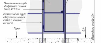
Machine made of plastic pipes. This option is good for those who have pipe scraps left after plumbing repairs. In another case, this option is very economical, since PVC pipes are cheaper than metal or wood. It’s not that difficult to make, the main thing is to maintain the proportions and dimensions.
These machines are easy to assemble, inexpensive and very convenient. But still, most often craftsmen prefer a more classic version.
Materials and tools for making the machine
Before starting work, you need to think through the sequence of all technological operations in the manufacture of a homemade machine, plan the manufacturing technology, decide on future materials and tools that will be needed during the work process.
To make a machine with your own hands, you will need the following materials and components:
- Plywood 15 mm.
- Pine board, solid;
- Furniture drawer guides;
- Sleeve;
- Furniture footwear;
- Wing nut;
- Fastening: M6 bolt, self-tapping screws of various lengths.
To make a machine from a drill or screwdriver, you will need the following tool:
- Circular saw or sawing machine.
- Jigsaw.
- Angle grinder (angle grinder or simply “grinder”).
- Drill or screwdriver.
- Grinding machine.
- Various hand tools: hammer, screwdriver, clamps, wood core drill (or simply “crown”), square, marking pencil, etc.
Drilling machine from a conventional drill
To make a small but functional drilling machine for your home workshop, you do not need to purchase special materials and components. The design of such a convenient and useful desktop device contains the following components:
- The base, which is also called the bed;
- a mechanism that ensures rotation of the working tool (a conventional drill can be used as such a mechanism);
- device for providing supply;
- a vertical stand on which the rotation mechanism is fixed.
Diagram of a homemade machine from a drill
The stand on which the drill will be mounted can be made from a sheet of chipboard. This material is quite capable of supporting the weight of such a device. The bed of such a mini-machine should be more massive, since it protects the entire structure from vibrations, which can negatively affect both the quality and accuracy of the resulting hole, and the comfort of work.
As the material for the frame of such a drilling and adding machine, you can use a regular furniture board, the thickness of which is more than 2 cm. It is most convenient to use the base of an old photographic enlarger for this, slightly modifying its design. Sometimes an old microscope is used, but this is a rather rare option, since such a unit will not be large enough and its use will be limited.
The quality and accuracy that a homemade drilling machine will provide depends primarily on how correctly and reliably the connection of its base and vertical stand is made. The important elements of such a micro machine are two guides along which the block with the drill attached to it will move. Such guides are best made from two strips of steel, which must be securely screwed to the rack using screws.
When making the block, it is advisable to use steel clamps that will securely fix the drill on it. In addition, in order to avoid unwanted vibration processes when drilling, a thick rubber gasket must be installed at the junction of the block and the drill.
After this, you need to make a feed mechanism for such a mini machine, which should ensure the movement of the electric drill in the vertical direction. The manufacturing schemes for such a mechanism can be different, but it traditionally contains in its design a lever and a spring, which is attached at one end to the stand, and at the other to the block with the drill. This spring gives the feed mechanism greater rigidity.
A drilling machine made from a drill, which is not planned to be removed from it, can be made more convenient to use if you disassemble the original switch of the drill and mount a separate button on the frame of the mini equipment. This button will always be at your fingertips and will allow you to quickly turn the device on and off. As you can see, it’s not at all difficult to make a drilling machine from a drill; all you need to do is read these instructions carefully or watch the training videos in this article.
Make or buy?
An electric drill is a ready-made drive, gear, spindle and chuck in a monoblock. Place it on the carriage of the machine and you can drill. In terms of accuracy, the solution, generally speaking, is not optimal (see below), but in many cases it is acceptable, but eliminates the need to order expensive turned parts of increased accuracy, see below. In view of this, frames for installing drills are now sold only on the street from trays; prices are affordable. When choosing one to make a drilling machine from a drill, be guided primarily by the operating mode of the equipment; The price also depends on it:
- Occasional drilling/milling for yourself with the accuracy of what you get - cast plastic bed or stamped steel. The feed mechanism is lever with a cranked lever (see below). Carriage sliding bearings (see below) are steel on steel or with nylon liners. Prices are $20-$30.
- Regular drilling for yourself or to order with ordinary machine-building precision. The materials processed are up to the hardness and toughness of ordinary structural steel. Everything is the same, but the sliding bearings are steel on steel (worse) or with bronze bushings, and the frame is cast iron or (more expensive) composite, also vibration-absorbing. Prices: $30-$40.
- Regular drilling and milling of any materials that can be tooled with periodic overloads of the tool and/or with increased accuracy - plain bearings are only bronze on steel, cast iron frame. The feed mechanism is rack and pinion (see below); vibration-absorbing console. Prices: $60-$180.
Note: as a rule, drill stands are optionally offered with a rotary-sliding table for the part, which allows for certain types of milling. Price within $20.
Choosing a bed
The stand for the drill (which sellers for some reason stubbornly call stands) must be chosen not according to - not “China”); Now the market is full of “German China”, not to mention products from post-Soviet states. The design needs to be checked.
First, samples with plastic non-nylon liners for sliding bearings are definitely rejected: runout and drill drift of more than 0.5 mm will appear already on the 10th – 20th “hole” and will further increase. The second is console play. We take it by the far end, swing it up and down and to the sides while holding the latch. There should be no noticeable “chatter” (the tactile sense of an untrained person feels a beat of 0.4-0.5 mm).
Next is an inspection of the structure, see Fig. below. For regular drilling, the one shown in pos. 1. The ideal option is at pos. 2: collet clamp of the drill, shifting the column to the side reduces the vibration of the console by an order of magnitude, and by turning it sideways by 45 degrees, you can mill the part by hand with the precision “as best you can” on a standard fixed table, removing a couple of table fasteners, because in this case, its manual displacement relative to the horizontal working axis of the console will be linear.
How to choose a bed (stand) for a drill
And here is a sample for pos. 3 do not take under any circumstances. Firstly, the collar of its column is low and its fastening is unreliable. Secondly, longitudinal grooves under the table facilitate manual milling “as it happens,” but, unlike diagonal ones, they do not dampen vibrations of the bed. Moreover, they will concentrate where shown by the arrows (the tide under the column is made too narrow) and from there they will go straight into the column and table.
Which is cheaper?
Bench Drill Press Spindle Drawings
Let’s say the price for the machine you like doesn’t suit you. Or a drill, if it’s a “crowbar” one, with an impact mechanism, that was used in work on building structures and the beating of the chuck is visible to the eye. Then the first thing we do is find out if there is a craftsman within reach who owns a lathe with high precision (no rougher than 0.02 mm). Which, by the way, is not a fact - a high-precision machine is very expensive and never pays off with the flow of regular orders. But let's say he was found. We take the drawing in Fig. on the right, we go to him and ask if he can turn it out of steel no worse than 30KhGSA, and how much he will charge for the work. “This” is the drawings of the tabletop drill spindle. The rest of its parts can be turned on a regular machine, or found in ruins at an iron market or in your trash. Most likely, it will turn out that it is cheaper to buy a bed + table, and if you estimate the costs for the rest, then perhaps a drill of increased accuracy will emerge. There are some of these on sale; they can be recognized by the absence of a striking mechanism and a collar specifically for installation in the frame: a turned steel cuff is put on it.
Homemade plywood machine
A drilling machine made of metal is durable and reliable. However, not every craftsman has a welding machine.
Therefore, we offer an alternative option - to make the frame and main parts of the drilling machine from plywood.
Please note: to assemble a homemade drilling machine, the author uses MDF, but it is better to use plywood.
Necessary materials:
- plywood;
- furniture guides;
- edged board;
- plastic legs;
- fastening clamp;
- metal plate.
First of all, we take two furniture guides, and after removing the internal movable slats, we screw them to the plywood blocks. The bars themselves will need to be secured to a wide piece, as shown in the photo.
Next, we take another pair of furniture rails - we screw them to the plywood platform between the side rails (we also remove the internal movable strips).
We make a mount for a drill. You must first cut off a metal plate and weld a clamp to it. Additionally, we make reinforcement using round or square rods (this is the only operation where welding is used).
Now you will need to make a movable platform. We saw off a piece of plywood of the required size and screw the internal strips of the furniture rails to it. We connect both parts of the structure together.
Another plywood board must be screwed to the movable platform, to which a metal plate with a clamp is attached.
After this, we cut out the base of the drilling machine and screw plastic legs to its lower part.
Next, we install a stand made of edged boards. The previously assembled structure must be attached to the rack.
Install the return spring. We fix the electric drill or screwdriver in the clamp.
Drilling machine made of profile pipe and bearings
Square metal profile is one of the most popular materials for making a benchtop drill press.
There are a lot of options for homemade structures made from corrugated steel pipes. Let's consider the most optimal, in our opinion, tabletop drill stand for a home workshop.
Necessary materials:
- profile pipe;
- threaded rod;
- bolts with nuts;
- metal corner;
- bearings;
- spring;
- channel;
- pieces of metal strip.
First of all, we make a stand. You will need a piece of thick metal (plate) and two pieces of corrugated pipe (20x20 mm and 25x25 mm). The length of each piece is 40 cm.
We drill mounting holes in the metal plate, and then weld two profiles to it.
We make a carriage from four pieces of square corrugated pipe 15x15 mm, as well as bolts with nuts and bearings.
A homemade carriage is placed on a stand made from a larger profile. We place a slider on the second rack measuring 20x20 mm.
We drill a hole in it. Then you need to weld the extended coupling. We strengthen the joint with metal gussets.
To fix the homemade slide at the desired height, use a wing nut.
Next, a lever made from a steel angle is attached to the slider and carriage. A handle made of a profile pipe must be welded to the lever.
A piece of channel is used as the base of the machine. We drill holes in it and fasten the metal plate with the stand using bolts.
In the end, all that remains is to make a mount for the drill. We attach it to the carriage. We install an electric drill. A spring is used to automatically return the carriage to its original position.
Capabilities and design of industrial drilling equipment
Drilling equipment intended for industrial use is much more complex than domestic models. This is noticeable, as mentioned above, even from photos of such units. Feeding of cutting tools on this equipment can be performed not only manually, but also in automatic mode. Almost any of these machines provides the ability to regulate the rotation speed of the spindle unit and the feed rate, for which the speed box and feed box are responsible, respectively.
Professional-class benchtop drilling machines differ from household models in high-precision components, from support bearings to chucks
Since such machines are used more intensively and for solving critical tasks, their kinematic design is more complex and reliable. Many of the modern models of these devices provide the option of automatically reversing the direction of feed and rotation of the cutting tool at the moment when it reaches the required processing depth.
The spindle assembly of most models of such equipment is equipped with a mechanism for automatically approaching the surface of the workpiece. An almost mandatory option for these machines is the automatic supply of coolant to the processing zone at the moment such processing begins.
Drilling head design of an industrial machine
Recently, industrial enterprises have been actively equipped with drilling machines, the operation of which is controlled by a CNC system. The advantage of using such equipment is that they automate the main and auxiliary technological operations, which can significantly increase their productivity compared to manually controlled models.
Industrial drilling machines, as mentioned above, are capable of performing various technological operations:
- opening holes;
- processing of holes using a countersink;
- chamfering in the upper part of the holes, forming cylindrical and conical recesses - countersinking;
- processing of holes using counterbore;
- internal thread cutting;
- processing of holes using a cutter - boring;
- finishing of holes using ball or roller tools - smoothing;
- processing of parts using milling tools (forming grooves, etc.).
Countersinking a recess on an industrial machine
Steering rack drilling machine
You can make a homemade drilling machine from a drill and a steering rack
Necessary materials:
- sheet metal;
- round pipe (steel);
- car steering rack;
- steel round timber;
- metal strip;
- electric drill.
We start by making the base. From sheet metal 2-3 mm thick, cut a rectangular blank of the required size. We round off sharp corners using an angle grinder.
Next, cut a piece of metal strip 30-40 mm wide.
We weld it to the bottom of the base, and immediately bend it along the contour of the workpiece. The bend area must first be heated with a gas burner, or you can first bend the strip to size on a bending machine.
Using a grinder with a petal wheel, we process the outer part of the base so that the edges are flush with the welded strip of metal.
After this we need a steel disk. We attach it to the base and fix it with welding. Then the author drills three holes to install the bolts - tighten them with nuts.
Now we need to make a vertical stand. A round pipe is used as the starting material. Use a grinder to cut the workpiece to the appropriate length. Using welding, we attach it to a metal disk.
Additionally, you need to strengthen the rack in the lower part with the help of three or four jibs cut from thick sheet metal.
Next, from a pipe and a pair of steel plates, you need to make a tightening clamp that fits onto the rack. It is needed to rigidly secure the working support table.
Two metal plates with holes are welded to the top of the rack, which are needed to secure the steering rack of the car.
A section of professional pipe is welded to the end of the rail, to which the master welds a homemade metal clamp, with which the electric drill will be rigidly fixed.
Now we need to make a support work table (we cut it out of a sheet of metal) and a flywheel to lower and raise the drill.
We clean the weld seams with a grinder with a flap wheel, after which the surface of the metal must be painted - it will last longer and be more beautiful.
The design turned out to be quite inexpensive and easy to use. It is very convenient that a drill is used as a drive - if necessary, it can be removed and used for other purposes.
If you do anyway
However, there may be cases when a homemade drilling machine will either be cheaper or completely free, or the best drill on the bed will not replace it. The fact is that, in addition to bending and vibration loads, torsional loads from the working tool (tool - drills, cutters) are also transmitted to the column. This is due to the difference in the lever arms from the axis of the column to the nearest and far edges of the tool; the torsional loads from a cutter gnawing the material with one edge are an order of magnitude greater than from a drill. Therefore, it is unrealistic to achieve a machining accuracy of more than 0.1 mm with a drill on a bed (see below for why), but let’s say a hole of 2.7 is needed for an M3 thread; under M2.5 – 2.2, and the processing error in this case turns out to be unacceptable. In general, making a drill with your own hands makes sense, despite the costs, if:
- You are a radio amateur and work with components with pin pitches of 2.5 and 1.25 mm (“millipedes” with a pitch of 0.625 mm are mounted only on a plane). Then you need a drilling machine for printed circuit boards with an accuracy of at least 0.05 mm;
- You do other fine wood and metal work. For example, it is impossible to make a beautiful, elegant box or a reliable hiding place in the house using only hand drilling;
- You drill/mill from time to time for yourself and the accuracy will suit you, but the stash is full of all sorts of junk metal.
Note: in the latter case, you are lucky, suddenly there is an old children's bicycle lying around somewhere. Its frame tubes are of excellent steel, and the wheel hub is almost a finished spindle; The only option available to order is an adapter with a Morse taper for a tool chuck. Working thoughtfully and carefully, an old bicycle can be turned into a drill press with an accuracy of approx. 0.1 mm, or actually a free drill stand, see for example. video:
Video: DIY drill stand
Layout
But let’s say we need higher accuracy, and we need to mill the grooves without losing it. In this case, the layout of the machine becomes of paramount importance.
The best option is to locate the spindle and drive on opposite sides of the column, pos. 1 in Fig. The heavy motor in this scheme acts as a counterweight to earthquake-resistant buildings: it reflects vibration and torsional loads from the spindle in antiphase. In the region, the columns partially cancel each other out. The damping is maximum if the center of gravity of the carriage is exactly along the axis of the console, and the higher, the thinner the drill and the less pressure on it. That is, the accuracy of the machine in delicate work increases, and at the same time, it can withstand quite significant overloads without losing it.
Layout diagrams of homemade drilling machines
Note 4: it is possible to make a drill for precise work with a direct drive to the spindle and the location of it and the drive on one side of the carriage if there is a ready-made vibration-damping frame, for example. from an old microscope (under 2), etc. optical devices.
In mini machines for printed circuit boards and jewelry work, an unpleasant effect is observed: in order to obtain an accuracy above 0.05 mm, the column has to be made disproportionately thick, pos. 3. This is due to the fact that its ability to absorb vibrations and torsional loads is determined by the cross-sectional area, which decreases squarely as the size of the part decreases. For circuit boards for components with a pin pitch of 2.5 mm, as well as minor metalwork and carpentry work, an accuracy of 0.05 m is sufficient. In this case, the main influence on its deterioration is exerted by column bending loads. To fend them off, it is enough to use a double column made of a 10-14 mm bar made of ordinary structural steel, pos. 4. If the usual accuracy of 0.375 mm is sufficient, then by doubling the column, a drilling machine for occasional work can be made even from a drill and propylene water pipes, pos. 5. Its service life before loss of accuracy is small, but the material is cheap and does not require custom processing.
Innings
The design of the spindle feed mechanism (carriage in a drill machine) also plays an important role in drilling accuracy: jerks and/or uneven feed force at least increase drill runout. When drilling with a thin carbide drill, in this case, it is very likely that it will slip, break, and, as a result, irreparable damage to the labor-intensive workpiece.
In machines and stands for high-precision drills, a rack-and-pinion feed mechanism is used (on the left in the figure), ensuring its complete uniformity and, which is especially important for manual feed, exactly proportional impact of the tool stop in the hand. This requires a rack and a gear-tribe with a well-defined tooth profile - involute. Otherwise, the feed will be jerky even with absolutely smooth pressure on the handle. It is unrealistic to make a rack-and-pinion pair with identical involute teeth “on the knee”; Finding a suitable ready-made pair is unlikely, so rack-and-pinion feed mechanisms are extremely rare in homemade drills.
Types of tabletop drilling machine feed mechanisms
More often they make a simple single-lever feed mechanism, in the center in the figure, but this is far from optimal. At the beginning and at the end of the working stroke, when the smoothness of the feed and the accuracy of drilling are especially important, it does not transmit enough emphasis to the hand, and in the middle of the stroke it is excessive, which increases the likelihood of the tool getting stuck in viscous material. The feed mechanism with a cranked breaking lever on the right is free from these shortcomings; in addition, it additionally dampens console vibrations. The knee shoulder ratio is taken to be approx. 1:1.
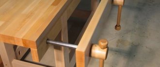
Serving table
Drilling thin, fragile/ductile parts is more accurate, and the likelihood of the drill leaving and breaking is less if the spindle is fixed and the table with the part is fed upward towards it, therefore, in many drills for fine work, the table is equipped with a separate feed mechanism. Due to the inertia of thinking, it is often also made rack and pinion, see for example. Further. But, taking into account that the mass of the table in this case is much greater than that of the part, a table with a lever feed turns out to be no worse, but completely accessible for manufacturing at home. Its device is shown in the figure:
Table design with lever feed for a drilling machine
There is only one nuance: to prevent the clip from moving during assembly, it is tightly inserted into the through hole of the base and welded from below (from the bottom). You need to cook with an OMA-2 electrode or thinner with a direct current of 55-60 A using short, diametrically opposed clamps (“poke”). Table dimensions for printed circuit boards and jewelry work are 60-150 mm in diameter; thickness 6-12 mm. Table shank diameter 12-20 mm; length per feed stroke +(20-30) mm. It is advisable to machine the tube for the shank (wall thickness from 1.5 mm) or drill it and pass it with a reamer so that the shank moves smoothly in it without noticeable play. The short lever arm is made to be approx. equal to the diameter of the table; long - whatever you want.
Console
Let's look again at Fig. with factory frames. The designs of their consoles with half-frame carriages are similar; they are quite rational, but are designed for automated and robotic production: precision casting and then finishing on site on a CNC unit with laser measurement.
A diagram of an analogue console with an amateur-made half-frame is shown on the left in the figure:
Console design of a homemade drilling machine
The first thing that attracts attention is that you need to cut out 5 parts from a thick steel sheet, trimmed (processed with an end mill) so that the sides are even and parallel. Second, the end cuts of inserts filled with dark gray must also be smooth, clean, and parallel. Those. and here you can’t do without a milling machine. Finally, outside production conditions, it is unrealistic to perform a sliding mating between the slider and the guide carriage (shown by the arrow) with a backlash of less than 0.1 mm. Let's estimate the ratio of the lever arms - the transverse runout of the drill turns out to be more than 0.5 mm.
The design of the console of a drilling machine, which is not technologically advanced in mass production, but is adapted for production using artisanal methods, is shown on the right in Fig. (the feed mechanism and drive with bracket are not shown). Moreover, in it, the runout of the drill on inhomogeneities of the material causes the carriage on the column and the guide to skew in opposite directions, and the lateral movement of the tool does not exceed the amount of play in the sliding liners. Only one part is cut out of a thick plate - slider 4. Its precise processing is necessary only in the area of clamping the column and installing the guide, and 3 bronze bushings-liners will be precisely adjusted in place by any turner of average qualification, if you give him a column and a carriage guide (they can be machined with normal precision).
To prevent the entire assembly from welding, you need to cook it as before. case: electrode OMA-2 or thinner, direct current up to 60 A. The seams are also welded alternately with tacks: a “poke” on one, the same on the same distant one, located symmetrically. Then tack the seam closest to the first, the same on the diametrically opposite one, etc., etc., until all the seams are welded.
Note: the accuracy of a machine with the described console will be higher if it is assembled not by welding, but by screws and gluing with high-strength metal glue (cold welding). First, everything is assembled without glue, the clips are checked for parallelism and the fasteners are tightened. Then the screws are turned out one by one, glue drips into the socket and screwed back tightly. It’s a tedious task, but in this way it’s possible to get a homemade drill with a drill runout of less than 0.02 mm. Unless, of course, the spindle and chuck are centered just as well.
Errors in design
All efforts to make a drilling machine with your own hands will go down the drain if fundamental errors were made during its design. The most common of them are shown in the figure:
Typical mistakes when making a drilling machine
Pos. 1 – is this a console or what? This frame will not withstand the normal load from the tool stop for long. There is no need to talk about accuracy. Pos. 2, in addition: it is impossible to make the column of the drilling machine tubular. The pipe can withstand bending loads, but is powerless against torsional loads, and only increases vibrations.
Pos. 3 – the temptation is great to make a drill from an old photographic enlarger, especially since it is made with at least initial, but optical precision. But! The magnifier rod holder is not designed to support the tool. As a result, when drilling hardboard, the drill drift at a feed rate of 20 mm reaches 1.5 mm (!). And the bracket is made of silumin: this material does not absorb vibration, gets tired quickly, and the bracket breaks in less than the 200th hole, even when drilling printed circuit boards.
Pos. 4 – doubling the column in the transverse direction does not give anything. The resistance of the machine to loads will be no higher than on a single pin of the same diameter. Pos. 5, in addition: a rebound spring that is asymmetrical relative to the axis of the column does not dampen vibrations and torsional loads, but enhances them. Since this is the case, it was necessary to install 2 identical springs on both racks. It would be better to make a column, as shown here:
Video: do-it-yourself drilling machine from a drill
Pos. 6 – installation of the drive and spindle on one side of the column, and even asymmetrical, does not reduce, but increases vibrations, because they are transmitted to the column in phase, see above. Pos. 7 – where is the bump stop? Yes, it cannot be here, since the feed drive is screw. Using a screw, you can accurately adjust the slider (which is not here at all), which is generally not necessary on a home machine, but under no circumstances should you feed the carriage! This structure will almost throw fragments of drills and shavings, and the operator’s eyes will be in close proximity to the danger zone.
5. Drilling machine driven by washing machine motor
We bring to your attention another budget option for a homemade drill. Only in this case, instead of an electric drill, the motor from the washing machine is used as a drive.
Necessary materials:
- round metal pipe;
- steel corner;
- strip of metal;
- Electrical engine;
- gas lift (shock absorber);
- plywood pulleys;
- belt for belt drive.
First we make a reinforced stand. Usually a profile pipe is used, but in this case it will not work. Instead, we will use a round pipe and a corner.
We take a grinder with a cutting disc to cut the workpieces to the required length. We weld the parts together and clean them with a grinder. Next, we weld the reinforced stand we made to the frame.
We would like to immediately draw your attention to the fact that the base must be heavy and stable enough to support the weight of the electric motor and metal parts.
From sections of corner and strip it is necessary to make a movable structural element that will lower and rise along the rack. Essentially, this part is a carriage with a mechanical feed mechanism.
Next, you need to make a mounting platform on which the motor will be placed. It is welded to the carriage made earlier.
Now you need to make a spindle with a chuck for fixing the drill.
To do this, we need a threaded pin at the end, which will act as the spindle shaft. We put the bearing on it and secure it with nuts.
We cut off a piece of the tube and place it on the pin. We install the second bearing on top of the tube.
We prepare another piece of pipe. We cut it along the entire length. Place it on the installed bearings. The longitudinal cut must be welded tightly. We screw the cartridge onto the shaft.
We weld the spindle body to a metal plate, and the plate itself to the moving part.
To be able to lower the spindle, a lever must be installed.
Instead of a return spring, the author decided to install a shock absorber (gas lift).
Now we are making a work table on which the workpieces will be placed. To do this, you will first need to make a small slider that will move along the rack.
We weld a round table to it (the author uses an old circular saw blade). Additionally, you need to make a retainer.
We machine two pulleys from wood or plywood. We install one pulley on the electric motor shaft, the second on the spindle shaft. We tighten the belt.
All the parts of the drilling machine need to be painted, and then we assemble everything into a heap. Install the on/off button.
Unlike the first option, this design turned out to be quite cumbersome. But such a machine will definitely be more powerful than a drill stand made from a drill.
Step-by-step manufacturing instructions
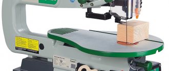
The following will provide detailed instructions on how to make a step-by-step circular saw driven by a washing machine engine.
Manufacturing of the bed
The table for a circular saw is a wooden box made of plywood, or in some cases a workbench knocked together from boards. The main requirement for the frame is stability and the ability to attach circular saw mechanisms.
If the circular saw will be used for long longitudinal cuts, then it is necessary to make a rectangular table, and mount the saw blade almost at the very end of the table at a distance of 20-30 centimeters from the edge.
Perforations are made in the table cover for a saw blade, which will be located under the tabletop of the station.
The frame must have a mass that will not allow the structure to move when cutting. This is very important because the kinetic energy from the rotation of the blade can resonate with the force of movement of the cutting board. As a result, the bed may move, creating a traumatic situation.
The circular saw table can be fixed to the floor, but for this you will have to install special mounting points and this will deprive the structure of mobility.
By the way, it is not necessary to make the table in the form of a box; a benchtop version is also possible.
Which drive should I use, direct or belt?
A circular saw with a washing machine motor can have two drive types: direct or belt. Both designs are valid, but direct drive circular saws are more reliable.
The absence of belts prevents them from breaking. Also, to mount the disk, you will need an additional driven shaft, to which torque will be transmitted from the engine through a belt drive. In this case, the rule applies: the fewer spare parts, the more reliable the mechanism. In addition, the presence of belts leads to increased vibration during operation.
Direct drive is reliable and easy to install, but it requires reliable fastening, since loosening the fasteners will lead to movement of the motor, and therefore to distortion of the disk, which is absolutely unacceptable.
We recommend using a motor with the ability to mount the saw blade directly onto the shaft.
Selecting a disk and mounting it on the engine or separately in the table
As already mentioned, it is better to use a direct drive in a circular saw. This will significantly simplify the design, while the functionality and performance of the saw will not deteriorate.
Disk selection
It is best to choose a universal-type carbide saw blade that has a medium tooth size.
These discs are different:
- Long service life with proper use.
- You can sharpen them yourself using a round file and a special template.
- Aluminum profiles can be sawed in small quantities.
Motor mount
It is best to place the engine under the bed because:
- It is safe for the operator of the circular saw.
- Electrical wiring is located at the bottom, which means it cannot enter the work area.
- You can make a reliable mount on one of the walls of the frame, and also fix the engine to the tabletop from below.
If for some reason the disk breaks or bends, then in 80% of cases it will remain under the table, and if the disk is located at the top, it will fly out along the rotation path.
How to attach?
The engine must be placed in brackets that will securely tighten it. The brackets themselves are attached to the wall and cover of the frame.
You can also make a small remote platform on brackets on which the engine will be mounted.
The figure shows the mounting of a motor with a belt drive on the metal frame of the future table.
And this way a direct drive engine can be mounted.
The main thing is that the mount is reliable and does not allow the engine to vibrate or move.
Motor connection
Old washing machines such as “Malyutka” or “Vyatka” have commutator-type motors in their design. Inverter, that is, brushless motors, are equipped with modern automatic washing machines. They are much more reliable than motors with a commutator (analogous to an electric drill motor), in that they do not contain current-collecting brushes and a graphite commutator.
The image shows a commutator motor with a remote power button.
It is necessary to remove wires from the cable entry point; there will be four of them: two supplying from the 220V network and two closed to the control (disconnecting) relay. It is through him that control is carried out.
A typical electrical circuit looks like this.
If you do not have knowledge in the field of electrical engineering, then you can connect the motor as follows - the “selection method”.
- Two power cables are output. They usually have the same color.
- The remaining two cables are routed to the side.
- The power cables are “connected” to the outlet with their bare ends. If the motor starts rotating, then the power cables are being used.
- A power button is mounted on the remaining two wires.
It is necessary to look at the actual connection of the motor cables while it is mounted on the washing machine. This will help you understand which ones supply power and which ones are mounted to the control relay.
Electrical part
The electrical part, in addition to connecting to the network, can be divided into two components.
Electronics:
- Start-stop button.
- Actuator.
The starter is a small box with an input, a stabilizer and a collector for current. Essentially, it delivers a charge of the required capacity to the engine. The starter is connected to a start-stop button, which makes or opens a contact.
Automation:
- Automatic shutdown relay.
- Rheostat regulator.
The relay is connected to the input of the electric motor and immediately turns it off in the event of a short circuit and voltage surges.
A rheostat is needed to regulate the speed. For small low-power circular machines, there is no need to connect it. In a homemade circular saw, it is necessary to reduce the number of revolutions when diagnosing engine operation.
To assemble the starter circuit and connection, special education at the level of an electrician is required. If you don’t have the necessary knowledge, it’s better to contact a specialist.
We recommend watching the video for more details on how to connect the motor from a washing machine. The author explains everything in great detail.
DIY drilling machine based on an electric drill
To make such a device you will need:
- a pair of used car shock absorbers;
- electric drill with power handle;
- two housing bearings;
- chain and sprocket;
- profile rectangular pipe;
- spindle feed handle;
- steel sheet, plates and angle;
- stud, bolts, washers and nuts;
- spring.
Let's make a vertical stand. According to the markings, we weld a piece of chain to the wide side of the profile pipe.
Let's make a mobile carriage. Using bearing housings, we mark and drill holes in the steel plate for fastening them with hardware.
We screw a nut onto the stud inserted through the bearing, put on the sprocket and secure it with a second nut.
We mark another plate for installation and welding in the center of the profile pipe.
We clean the old shock absorbers, and after drilling the bottoms, drain the oil and knock off the covers. After wrapping the mirrors of the rods and threads with aluminum foil, we place them in the shot blasting chamber for complete cleaning. Finally, remove the levers.
We place the shock absorbers with their upper parts in the corners at the level of the sloping shelves and weld them.
We fix the shock absorbers parallel to the steel plate at the corners using welding.
We apply a piece of profile pipe to the ends of the painted rods and drill two holes along the marks.
We lay it flat and place a U-shaped bracket in the center with its legs facing outwards and weld it.
For a piece of profile pipe with a length equal to the width of the larger side, remove the opposite edge. Drill a hole in the center of the square base.
We cut a piece of round pipe along the generatrix and weld ears with two holes along the edges of the cut. It turned out to be a kind of clamp.
Insert a bolt into a part made from a profile pipe from the inside and weld it behind the head. We fix the hardware in a vice, place the clamp along the legs with the ears up and connect them by welding.
We place the U-shaped bracket on the profile pipe between the shock absorbers, then the rods will fit into its holes. Screw the nuts onto the threads of the rods and tighten them.
In the photo: clamp for attaching a drill
We turn the shock absorbers over and place an assembly of bearing housings, pins and sprockets on the bracket leg. We weld the assembly plate to the bracket.
We place it on the assembly, then the sprocket will engage with the chain, and weld the shock absorbers to the plates.
Let's make a base for the machine.
We attach a vertical stand to the base of the machine with bolts.
We put the spindle feed handle on the pin and secure it with a nut. For convenience, we screw plastic balls onto the handles.
We secure the drill with a clamp.
The drilling machine is ready for use, so that it is convenient to use workpieces when drilling, we will install a vice on the base of the machine.
Tabletop drilling machine made from drill
The most common design can be considered a machine made from a hand or electric drill, which can be made removable, so that it can be used outside the machine, or stationary. In the latter case, the switching device can be moved to the frame for greater convenience.
The main elements of the machine are:
- drill;
- base;
- rack;
- drill mount;
- feed mechanism.
The base or frame can be made from a solid cut of hard wood, furniture board or chipboard. Some people prefer a metal plate, channel or tee as a base. The bed must be massive to ensure structural stability and compensate for vibrations during drilling to produce neat and accurate holes. The size of the frame made of wood is at least 600x600x30 mm, of sheet steel - 500x500x15 mm. For greater stability, the base can be made with eyes or holes for bolts and attached to the workbench.
The stand can be made of timber, round or square steel pipe. Some craftsmen use the frame of an old photographic enlarger, a substandard school microscope, and other parts that have a suitable configuration, strength and weight as a base and stand.
The drill is secured using clamps or brackets with a hole in the center. The bracket is more reliable and provides greater accuracy when drilling.
Machine based on the steering rack of a passenger car
A steering rack for a car and a drill are quite massive products, so the frame should also be massive and, preferably, with the ability to attach the machine to a workbench. All elements are welded, since connections with bolts and screws may not be sufficient.
The frame and support post are welded from channels or other suitable rolled products, about 5 mm thick. The steering rack is secured to a stand, which should be 70–80 mm longer than the rack, through the eyes of the steering column.
To make the machine more convenient to use, the drill control is placed in a separate unit.
Assembly procedure for tabletop drilling machines:
- preparation of all elements;
- attaching the stand to the frame (check verticality!);
- assembly of the movement mechanism;
- fastening the mechanism to the rack;
- fastening the drill (check verticality!).
All fastenings must be made as securely as possible. It is advisable to join one-piece steel structures by welding. When using any kind of guides, you need to make sure that there is no lateral play during movement.
Advice! To fix the part in which the hole is drilled, the machine can be equipped with a vice.
You can also find ready-made stands for drills on sale. When purchasing, you need to pay attention to the weight of the structure and the size of the working surface. Lightweight (up to 3 kg) and inexpensive (up to 1.5 thousand rubles) racks are suitable for making holes in a thin plywood sheet.
Video
We have made a selection of interesting videos, the authors of which offer interesting ideas for creating a circular machine using the motor from an automatic washing machine. Each video is interesting in its own way and each can be used as a step-by-step guide for assembling your own machine.
The first video is a circular saw on a metal table using a drill chuck, direct drive.
Second video. Option for a serious machine on a metal bed
Homemade drilling machine from a drill with an engine from household appliances - step-by-step manufacturing diagram
A home drill can be used as the main element of a self-assembled drilling machine, for installation of which you will need:
- bed or stable and reliable base;
- device providing power supply;
- securing base for the drilling element.
As a result of the assembly, the master will have a high-quality and productive drilling and additive machine, which has its own benefits.
Design advantages
Machines for drilling deep holes assembled using an electric drill are distinguished by a range of operational advantages:
- optimal compactness and low weight of the structure;
- Possibility to carry and use batteries;
- obtaining high-quality and accurate hole parameters;
- quick assembly and dismantling of equipment without wasting time;
- performing various works and processing all materials.
For repairs and home maintenance, a machine will be enough, but for a garage and larger-scale procedures it is better to choose a different type of device.
Asynchronous motor
By choosing alternative options from which to assemble a drilling machine, you can abandon the idea of using an electric drill needed on the farm.
For the rotation mechanism, you can use a motor of any power with an electric drive; it can be easily removed from old equipment and household appliances.
Manufacturing Features
The procedure for making a drilling machine with your own hands is not complicated, but you must take into account the advice of the experts:
- for a small drilling machine it is better to choose an asynchronous motor from an old washing machine;
- to install a sufficiently powerful engine, you will need a more durable and as stable base as possible;
- During the design and assembly of the installation, it is important to place the engine closer to the rack, which will reduce the vibration level;
- the connection using hexagons should be as strong and reliable as possible to increase the wear resistance of the unit.
This machine is more difficult to assemble even with an accessible circuit, but its main advantage remains increased power, which is suitable for processing different surfaces.
Which engine to choose?
Let's consider the requirements that apply to the engine from a washing machine in order to effectively use it to equip a circular saw.
You will need a motor with a power range from 120 to 2000 W. It all depends on the amount of work planned for the circular saw.
Circular saws have the following power characteristics.
| Characteristic | Power range, W |
| Lightweight | 120 to 1000 |
| Average | 1000-1500 |
| Heavy | 1500-2000 |
120 W is the minimum limit for the power of a circular saw. To equip it, miniature disks with a diameter of up to 10 centimeters are used, which allow cutting a bar of 5-7 centimeters. Motors of this power were installed on top-loading washing machines of the “Malyutka” type.
For higher performance, it is recommended to select motors with a power rating that matches the category of medium and heavy circular saws. In this range, among Soviet and Russian cars, the “Vyatka” and “Vyatka-Avtomat” models have proven themselves to be excellent.
In addition, the engine must have the following configuration and design:
- A BRNO, that is, a cable gland, is mounted on the engine. It will be needed to equip the circular saw with a control system.
- The motor has a straight shape, the shaft directly receives movement from the gearbox without hypoid gears. Other designs complicate installation.
- The shaft should “extend” from the gearbox by 5-7 centimeters.
The engine from the car is automatic
For a homemade circular saw, an engine from any modern washing machine—an automatic machine—is suitable. The manufacturer does not matter, you can choose any: LG, Samsung, Bosch, Ariston.
Such an engine has good characteristics, for example, a large number of revolutions, up to 15,000 rpm and sufficient power, up to 700 W. Also, many models are equipped with a built-in tachometer - revolution counter. By the way, you can use it to regulate the speed of the circular.
It is worth noting that 15,000 revolutions for a circular saw is a lot and is therefore life-threatening if the blade jams. In tools of this type, the number of revolutions per minute should not exceed 6,000 - 7,000 rpm. In a homemade tool, it is necessary to reduce this indicator using a rheostat or the same tachometer.
It is better to choose the simplest engine (without tachometers and protective devices), which can be started using a regular start-stop button through an automatic starter. For this task, motors with the least number of wires going inside it are suitable.
How to make your own PCB drilling machine
A printed circuit board is a plate made of dielectric material, on the surface of which is applied a layer of metal that conducts electric current. The thickness of such products is 1.5–4.5 mm.
In this regard, a drilling machine designed for drilling printed circuit boards is a mini-machine, so when manufacturing it, the following features must be taken into account:
- such a machine does not need large electrical power;
- there is no need for a significant stroke of the machine head with a drill installed in it;
- the machine must be small in size, allowing it to be used on the desktop of a radio amateur or a person engaged in the manufacture of electronic systems;
- the absence of the need for significant power makes it possible to perform a similar installation at a lower voltage class and without the use of bulky chucks designed for installing large-diameter drills;
- On machines for this purpose, special adapters and collets are used to install drills, due to their small diameters.
Working with printed circuit boards is a “delicate” and scrupulous task that requires careful work and precision of the holes made.
You can make a homemade drilling machine for printed circuit boards using the technology considered in the case of using an electric drill or screwdriver, with the only difference being that electric motors of lower voltage and size can be used as a drive.
Making a drill from a car steering rack
For many, this solution will not be obvious, but experts will immediately appreciate its simplicity and functionality. We make a drill based on the steering rack of a car. To do this, you only need the rack itself from an old decommissioned, disassembled car, or just a rack from a car that no longer exists.
You will also need fasteners and the drill itself. A steering rack drilling machine is an excellent solution for permanent work!
Homemade drilling machines - photo gallery
Sources
- https://nzmetallspb.ru/osnastika/sverlilnye-stanki-svoimi-rukami.html
- https://protechniky.ru/remont/kak-sdelat-samodelnyj-sverlilnyj-stanok-svoimi-rukami-chertezhi
- https://stroitelcentr.ru/idei-kak-sdelat-stanok-dlya-sverleniya/
- https://armatool.ru/sverlilnye-stanki-iz-dreli-svoimi-rukami/
- https://met-all.org/oborudovanie/stanki-sverlilnye/sverlilnyj-stanok-iz-dreli-svoimi-rukami.html
- https://sdelairukami.ru/sverlilnyj-stanok-svoimi-rukami-na-baze-elektrodreli/
- https://sam-stroitel.com/prostoj-sverlilnyj-stanok-svoimi-rukami-39-foto-izgotovleniya.html
- https://www.rmnt.ru/story/instrument/nastolnyy-sverlilnyy-stanok-svoimi-rukami-sxemy-ichertezhi.1229327/
- https://camodelkin.ru/instrument/samodelnyj-sverlilnyj-stanok-iz-dreli.html
- https://podelki.expert/sverlilnyj-stanok-svoimi-rukami/
- https://svoimirykamiinfo.ru/sverlilnyj-stanok-svoimi-rukami/