14Nov
- By: Semantics
- Uncategorized
- Comments: 0
When constructing objects, it is imperative to use calculations that include detailed characteristics of building materials. Otherwise, too much, unbearable load may be placed on the support, which will cause destruction. Today we’ll talk about the tensile strength of a material at break and tension, we’ll tell you what it is and how to work with this indication.
Tensile strength
PP - we will use this abbreviation, and we can also talk about the official combination “temporary resistance” - this is the maximum mechanical force that can be applied to an object before its destruction begins. In this case, we are not talking about chemical effects, but we mean that heating, unfavorable climatic conditions, and a certain environment can either improve the properties of the metal (as well as wood, plastic) or worsen it.
No engineer uses extreme values when designing, because it is necessary to leave a permissible error - for environmental factors, for the duration of operation. We told you what is called tensile strength, now let’s move on to the specifics of the definition.
How is the strength test performed?
Initially there were no special events. People took an item, used it, and as soon as it broke, they analyzed the breakdown and reduced the load on a similar product. Now the procedure is much more complicated, however, until now the most objective way to find out PP is the empirical way, that is, experiments and experiments.
All tests are carried out under special conditions with a large amount of precise equipment that records the condition and characteristics of the experimental material. Usually it is fixed and experiences various influences - tension, compression. They are performed by instruments with high precision - every thousandth of a newton of the applied force is noted. At the same time, each deformation is recorded as it occurs. Another method is not laboratory, but computational. But usually mathematical analysis is used in conjunction with testing.
Definition of the term
The sample is stretched on a testing machine. In this case, first it lengthens in size, and the cross-section becomes narrower, and then a neck is formed - the place where the thinnest diameter is, this is where the workpiece will rupture. This is true for ductile alloys, while brittle alloys, such as cast iron and hard steel, stretch very slightly without necking. Let's take a closer look at the video:
Tensile Chart of Low Carbon Steel
In Fig. Figure 3.2 shows the tensile diagram of low-carbon steel (art. 3), recorded using a special device on a testing machine.
In the initial stage of loading to a certain point A, the tensile diagram is an inclined straight line, which indicates the proportionality between load and deformation - the validity of Hooke's law. The load at which this proportionality is not yet violated is indicated in the diagram by Ppc
and is used to calculate the proportionality limit:
, (3.1)
where F
– cross-sectional area of the sample before testing.
The limit of proportionality is the maximum stress up to which there is a directly proportional relationship between load and deformation. For Art. 3, the proportionality limit is approximately equal to MPa.
The OA zone is called the elastic zone. Here only elastic, very slight deformations occur. The data characterizing this zone allows us to determine the value of the elastic modulus E
.
After reaching the limit of proportionality, the deformation begins to increase faster than the load, and the diagram becomes curvilinear. In this area, in close proximity to point A, there is point B, corresponding to the elastic limit.
The elastic limit is the maximum stress at which no signs of plastic (residual) deformation are detected in the material.
The elastic limit exists regardless of the law of direct proportionality. It characterizes the beginning of the transition from elastic to plastic deformation.
For most metals, the values of the proportional limit and the elastic limit differ slightly from each other. Therefore, they are usually considered to be practically identical. For steel st. 3 MPa.
With further loading, the curvilinear part of the diagram transforms into an almost horizontal section CD - the yield plateau. Here the deformations increase practically without increasing the load. Load RT
, corresponding to point D, is used to determine the physical yield strength:
(3.2)
The physical yield strength is the lowest stress at which a sample deforms without a noticeable increase in tensile load.
The yield strength is one of the main mechanical characteristics of the strength of metals. For steel st. 3 MPa.
The BD zone is called the general flow zone. Plastic deformations develop significantly in this zone. At the same time, the temperature of the sample increases, the electrical conductivity and magnetic properties change.
The diagram after the yield zone again becomes curvilinear. The sample acquires the ability to perceive increasing force up to the value Pmax
– point
E
on the diagram.
The force Pmax
is used to calculate the tensile strength:
. (3.3)
The stress corresponding to the greatest load preceding the failure of the sample is called temporary resistance .
For steel grade st.3, the temporary resistance is MPa.
The DE zone is called the hardening zone. Here, the elongation of the sample occurs uniformly along its entire length, the original cylindrical shape of the sample is preserved, and the cross sections change slightly and also uniformly.
At maximum force or slightly less than it, a local decrease in the cross section appears on the sample at the weakest point - a neck (and sometimes two). Further deformation occurs in this specimen call. The cross section in the middle of the neck continues to rapidly decrease, but the stresses in this section are constantly increasing, although the tensile force is decreasing. Outside the neck region, the stresses decrease, and therefore elongation of the rest of the sample does not occur. Finally, at point K the sample is destroyed. The force corresponding to point K is called destructive Pk
, and the stresses are
the true tensile strength (true tensile strength), which are equal to:
, (3.4)
where Fк
– cross-sectional area at the rupture site.
Zone EK is called the local yield zone. True stresses at the moment of rupture (in the neck) in a sample made of steel grade 3 reach 900.1000 MPa.
The mechanism of destruction of a low-carbon steel sample is interesting. The sample is destroyed, as a rule, with the formation of a “cup” on one part and a “cone” on the other. This fracture is called a cup fracture or cup-to-cone fracture.
In addition to the indicated strength characteristics, after the destruction of the sample, the plasticity characteristics are determined.
Relative elongation after rupture (%) is the ratio of the increment in the estimated length of the sample after rupture to its initial value, calculated by the formula:
Tensile strength of steel
Steel structures have long replaced other materials, as they have excellent performance characteristics - durability, reliability and safety. Depending on the technology used, it is divided into brands. From the most common with a PP of 300 MPa, to the hardest with a high carbon content - 900 MPa. This depends on two indicators:
- What heat treatment methods were used - annealing, hardening, cryotreatment.
- What impurities are contained in the composition. Some are considered harmful, they are discarded for the purity of the alloy, and others are added to strengthen them.
Properties determined by tensile testing and factors influencing them
Tensile strength
The tensile strength is the maximum tensile force per unit area of its initial section
σВ = P/F
,
Pa
. In other words, the tensile strength is the conditional maximum stress that the material can withstand when stretched. By “true tensile strength” (or actual tensile strength) we mean the force at the moment of rupture P
, related to the cross-sectional area.
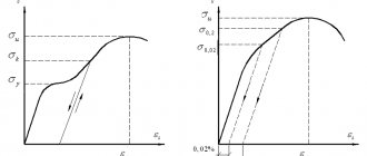
Limit of proportionality and elasticity
Under the proportionality limit σПЦ
understand the minimum stress that causes a deviation from the law of proportionality in the test material (or the greatest stress from this law), and the elastic limit
σUP
is the maximum stress, below which the amount of deformation is a certain function of stress, regardless of the increase or decrease of the latter, then there is no reason to assume identity these two quantities.
Yield strength
Yield strength σТ
is called the stress at which the resulting residual deformation of the sample spreads uniformly over its working part with temporary constancy of the tensile force.
In practice, the yield stress is usually taken to be the stress at which the deformation of the sample increases and the dynamometer pointer of the tensile testing machine either stops or moves back. In this case, a so-called yield plateau is formed on the stress-strain curve (curve a
), and then the yield strength is called explicit or physical.
Typical tensile curves (α - ε)
In some cases, the yield plateau is not clearly expressed (curve b
) or completely absent (curve
in
);
Very ductile metals (for example, copper) have this shape of curves at normal testing temperatures. With an increase in temperature and an obvious yield stress, the shape of the curve has the form shown in the figure, c
.
Mild carbon steel with a content of 0.05% at 300°C gives a curve corresponding to curve b
;
other, more heat-resistant steels retain a clear yield strength up to 400 and even up to 500 ° C; above these temperatures, the shape of the stress-strain curves is similar to the curve in
.
In all cases where there is no obvious yield strength, it is necessary to resort to finding the so-called conditional yield strengths, based on determining the stresses that cause a given residual deformation of small magnitude (within 0.01-0.5%). Most often in practice, conditional yield limits are determined that cause residual deformation equal to 0.1 or 0.2%.
Conditional yield strengths of some alloy steels
If the proof limits at normal temperature differ little from each other, then at high temperatures the difference between the proof limits, for example 0.01 and 0.2% (after fluidity), becomes significant.
Elongation and transverse contraction of the sample
The elongation and transverse contraction of a sample tested at high temperature are indicators of the plastic properties of the metal at a given temperature.
Elongation δ
and transverse contraction
ψ
are measured on cooled samples and calculated using well-known formulas:
- where l0
is the initial length of the calculated section of the sample; - lk
is the final length of the calculated section of the sample; - F0
is the initial cross-sectional area of the sample; - Fk
is the final cross-sectional area of the sample.
The greatest influence on these properties is exerted by the time to rupture or, what is the same, the rate of stretching of the sample.
Elastic modulus
Modulus of normal elasticity E
is an important physical and mechanical characteristic of the metal. Knowledge of the elastic modulus of steel for a wide temperature range is necessary not only for design calculations of machine parts and equipment operating at elevated temperatures, but also in a number of other cases.
Relative change in elastic modulus E (in % of its value at 20°) depending on temperature for steels: 1-unalloyed; 2-low alloy; 3-medium alloyed; 4-high alloy
Fatigue of steel
The second name is endurance limit. It is denoted by the letter R. This is a similar indicator, that is, it determines what force can act on an element, but not in a single case, but in a cycle. That is, certain pressures are applied to the experimental standard cyclically, over and over again. The average number of repetitions is 10 to the seventh power. This is exactly how many times the metal must withstand the impact without deformation or loss of its characteristics.
If you carry out empirical tests, it will take a lot of time - you need to check all the force values, applying it over many cycles. Therefore, the coefficient is usually calculated mathematically.
Proportionality limit
This is an indicator that determines the duration of the loads applied to the deformation of the body. In this case, both values should change to different degrees according to Hooke’s law. In simple words: the greater the compression (tension), the more the sample is deformed.
The value of each material lies between absolute and classical elasticity. That is, if the changes are reversible after the force ceases to act (the shape becomes the same - for example, compression of a spring), then such parameters cannot be called proportional.
Stress diagrams
Today, there are several methods for testing material samples. At the same time, one of the simplest and most revealing tests are tensile (tensile) tests, which make it possible to determine the proportionality limit, yield strength, elastic modulus and other important characteristics of the material. Since the most important characteristic of the stressed state of a material is deformation, determining the deformation value for known dimensions of the sample and the loads acting on the sample makes it possible to establish the above characteristics of the material.
Here the question may arise: why can’t we simply determine the resistance of a material? The fact is that absolutely elastic materials, which collapse only after overcoming a certain limit - resistance, exist only in theory. In reality, most materials have both elastic and plastic properties; we will consider what these properties are below using the example of metals.
Tensile tests of metals are carried out in accordance with GOST 1497-84. For this purpose, standard samples are used. The test procedure looks something like this: a static load is applied to the sample, the absolute elongation of the sample Δl is determined, then the load is increased by a certain step value and the absolute elongation of the sample is determined again, and so on. Based on the data obtained, a graph of elongation versus load is constructed. This graph is called a stress diagram.
Figure 318.1 . Stress diagram for a steel sample.
In this diagram we see 5 characteristic points:
Proportionality limit Рп (point A)
Normal stresses in the cross section of the sample when the proportionality limit is reached will be equal to:
σп = Рп/Fo (318.2.1)
The proportionality limit limits the area of elastic deformations on the diagram. In this section, the deformations are directly proportional to the stresses, which is expressed by Hooke’s law:
Рп = kΔl (318.2.2)
where k is the stiffness coefficient:
k = EF/l (318.2.3)
where l is the sample length, F is the cross-sectional area, E is Young’s modulus.
How are the properties of metals determined?
They check not only what is called tensile strength, but also other characteristics of steel, for example, hardness. The tests are carried out as follows: a ball or cone made of diamond, the most durable rock, is pressed into the sample. The stronger the material, the smaller the mark left. Deeper, wider-diameter prints are left on soft alloys. Another experience - for a blow. The impact occurs only after a pre-made cut on the workpiece. That is, the destruction is checked for the most vulnerable area.
Mild Steel Tensile Chart
Straight-line section 1 of the diagram (strains increase in proportion to stress o) turns into a curve (small segment between sections 1 and 2), i.e., deformations grow faster than the increase in load, and from the starting point (“critical point”) of section 2, deformations increase without increasing load (material “flows”).
At stresses close to the temporary resistance σi, longitudinal and transverse deformations are concentrated in the weakest place, and a neck is formed in the sample. The cross-sectional area in the neck decreases rapidly, which leads to an increase in stress at the narrowing site. In this regard, despite the fact that the load on the sample is reduced, at the site of necking the interatomic adhesion forces are disrupted and rupture occurs.
The stresses (figure above) are obtained by dividing the load by the original cross-sectional area. The true tensile diagram (at stresses taking into account the reduction in cross-sectional area) does not have a descending part.
When conducting tensile tests, the cross-sectional area of periodic profile rods with an untreated surface can be determined by the formula
where G is the weight of a sample of a periodic profile rod, N; L—sample length, cm.
The yield point is characteristic of steels with a carbon content of 0.1-0.3%. At a lower carbon value, there are few pearlite inclusions, which is why there is no restraining effect on the development of shifts in ferrite grains.
In high-strength steels with a large number of inclusions, the development of shears is completely blocked and there is no clearly defined yield plateau, i.e. the material has no physical yield strength; it is necessary to determine the value of the conditional yield strength as the stress corresponding to the residual elongation Δε0.2 = 0.2% ε , where ε is the elongation of the sample.
The conditional yield strength for such rod reinforcement σ0.2 is established by the residual elongation equal to 0.2%, and must be at least 80% of the rejection value of the tensile strength for each type of reinforcement (Fig. below). Plotting the value Δε0.2 on the appropriate scale on the x-axis of the tensile diagram, we draw an inclined line BC parallel to OA until it intersects with the tensile curve. Point B determines the load σ0.2, corresponding to the conditional yield strength.
Mechanical properties
There are 5 characteristics:
- The tensile and tensile strength of steel is temporary resistance to external forces, stress arising internally.
- Plasticity is the ability to deform, change shape, but maintain the internal structure.
- Hardness – willingness to meet harder material without causing significant damage.
- Impact strength is the ability to resist impacts.
- Fatigue is the duration of preservation of qualities under the influence of cyclic loads.
Reinforcing steel
The main indicators of the properties of reinforcing steel are:
- Yield strength (physical) σу, MPa.
- For steels that do not have a physical yield strength, the yield strength (conditional) is determined σ0.2, MPa - the stress at which the permanent elongation reaches 0.2% of the length of the sample section. It is determined when, when the sample is stretched, no pronounced yield strength is detected (hard steels).
- Tensile strength (tensile strength) σi, MPa.
- Relative elongation after rupture ε is the percentage ratio of the length of the sample after rupture to its original length.
When testing a sample, the load on it is increased gradually, in steps. The initial loading stage should be 5-10% of the expected maximum load. Each stage should be no more than 20% of the standard load. At the end of each stage, the increase in load on the sample is stopped. The sample remains under this load for at least 10 minutes. Having brought the load to the standard value, the sample is held for 30 minutes. These excerpts are necessary to clarify the pattern of increment in displacements and deformations.
After the load reaches one and a half times the standard value, further increase is carried out in steps half as large, allowing a holding time of at least 15 minutes after each step. This procedure makes it possible to more accurately determine the value of the ultimate (destructive) load.
It is recommended to measure deformations with instruments until the load reaches a value of no more than 1.25 of the standard value. After this, the devices are removed. This is done to avoid damage to the devices.
The initial design length of cylindrical samples made of untreated reinforcing steel is assigned equal to ten initial (before testing) diameters of the reinforcing bar.
Measurement of the initial and final (length of the calculated part after breaking the sample) calculated lengths, as well as the diameter of the unprocessed sample, is carried out with an accuracy of 0.1 mm. Before the sample deformation occurs, the movable gripper moves without increasing or with a slight increase in load, which is necessary to eliminate the gap both in the machine mechanism and between the samples and the grippers. Therefore, at the very beginning of the test, first a horizontal and then a curved section appears on the diagram. At an initial load of 10% of the breaking force, two marks are applied to the sample. The distance between the marks is the initial calculated length of the sample.
Throughout the test, the behavior of the sample is monitored using a diagram drawn by the recording device of the tensile testing machine.
The stress σ is plotted along the ordinate axis of the diagram, and the relative deformations of the sample ε are plotted along the abscissa axis, representing the ratio of the elongation of the sample to its original length (Fig. below). The curved section at the beginning of the diagram should not be considered, so we continue the straight section of the diagram to the abscissa axis and get point O - the beginning of the diagram.
In the diagram (Fig. below) three sections of steel work can be distinguished: 1 - section of elastic work; 2 - area of plastic work; 3 - area of elastic-plastic work. In most simple calculations, it is assumed that steel operates elastically within the first section, that is, the stresses in the elements are limited by the yield strength - σy. Accordingly, the standard and design resistances necessary for the calculation of structures are taken according to the yield strength.
Strength classes and their designations
All categories are written down in regulatory documents - GOSTs, according to which all Russian entrepreneurs produce any rolled metal and other metal products. Here is the correspondence between the designation and parameter in the table:
| Class | Tensile strength, N/mm2 |
| 265 | 430 |
| 295 | 430 |
| 315 | 450 |
| 325 | 450 |
| 345 | 490 |
| 355 | 490 |
| 375 | 510 |
| 390 | 510 |
| 440 | 590 |
We see that for some classes the PP indicators remain the same, this is explained by the fact that, with equal values, their fluidity or relative elongation may differ. Depending on this, different maximum thickness of rolled metal is possible.
Elastic moduli
The main characteristics of the elastic properties of materials are Young's modulus E (modulus of elasticity of the first kind, modulus of elasticity in tension), modulus of elasticity of the second kind G (modulus of elasticity in shear) and Poisson's ratio μ (transverse deformation coefficient).
Young's modulus E shows the ratio of normal stresses to relative strains within the limits of proportionality
Young's modulus is also determined empirically when testing standard tensile specimens. Since the normal stresses in the material are equal to the force divided by the initial cross-sectional area:
σ = Р/Fо (318.3.1), (317.2)
and relative elongation ε - the ratio of absolute deformation to the initial length
εpr = Δl/lo (318.3.2)
then Young’s modulus according to Hooke’s law can be expressed as follows
E = σ/εpr = Plo/FoΔl = tgα (318.3.3)
Figure 318.2 . Stress diagrams of some metal alloys
Poisson's ratio μ shows the ratio of transverse to longitudinal strains
Under the influence of loads, not only does the length of the sample increase, but also the area of the cross-section under consideration decreases (if we assume that the volume of material in the region of elastic deformation remains constant, then an increase in the length of the sample leads to a decrease in the cross-sectional area). For a sample having a circular cross-section, the change in cross-sectional area can be expressed as follows:
εpop = Δd/do (318.3.4)
Then Poisson's ratio can be expressed by the following equation:
μ = εpop/εpr (318.3.5)
The shear modulus G shows the ratio of tangential stresses t to the shear angle
The shear modulus G can be determined experimentally by testing specimens for torsion.
During angular deformations, the section under consideration does not move linearly, but at a certain angle—the shear angle γ to the initial section. Since the shear stress is equal to the force divided by the area in the plane in which the force acts:
t = P/F (318.3.6)
and the tangent of the angle of inclination can be expressed as the ratio of the absolute deformation Δl to the distance h from the place where the absolute deformation was recorded to the point relative to which the rotation was made:
tgγ = Δl/h (318.3.7)
then at small values of the shear angle the shear modulus can be expressed by the following equation:
G = m/γ = Ph/FΔl (318.3.8)
Young's modulus, shear modulus and Poisson's ratio are related to each other by the following relationship:
E = 2(1 + μ)G (318.3.9)
The values of the constants E, G and µ are given in table 318.1
Table 318.1 . Approximate values of the elastic characteristics of some materials
Note: Elastic moduli are constant values, however, manufacturing technologies for various building materials change and more accurate values of elastic moduli should be clarified according to currently valid regulatory documents. The modulus of elasticity of concrete depends on the class of concrete and therefore is not given here.
Elastic characteristics are determined for various materials within the limits of elastic deformations limited on the stress diagram by point A. Meanwhile, several more points can be identified on the stress diagram:
Elastic limit Ru
Normal stresses in the cross section of the sample when the elastic limit is reached will be equal to:
σу = Ru/Fo (318.2.4)
The elastic limit limits the area in which the appearing plastic deformations are within a certain small value, normalized by technical conditions (for example, 0.001%; 0.01%, etc.). Sometimes the elastic limit is designated according to the tolerance σ0.001, σ0.01, etc.
Yield strength RT
σт = Рт/Fo (318.2.5)
Limits the area of the diagram in which the deformation increases without a significant increase in load (yield state). In this case, a partial rupture of internal bonds occurs throughout the entire volume of the sample, which leads to significant plastic deformations. The sample material is not completely destroyed, but its initial geometric dimensions undergo irreversible changes. On the polished surface of the samples, yield figures are observed - shear lines (discovered by Professor V.D. Chernov). For different metals, the angles of inclination of these lines are different, but are in the range of 40-50o. In this case, part of the accumulated potential energy is irreversibly spent on the partial rupture of internal bonds. When testing tensile strength, it is customary to distinguish between the upper and lower yield limits - respectively, the highest and lowest stresses at which plastic (residual) deformation increases at an almost constant value of the acting load.
The stress diagrams indicate the lower yield strength. It is this limit for most materials that is taken as the standard resistance of the material.
Some materials do not have a pronounced yield plateau. For them, the conditional yield strength σ0.2 is taken to be the stress at which the residual elongation of the sample reaches a value of ε ≈0.2%.
Tensile strength Pmax (temporary strength)
Normal stresses in the cross section of the sample when the ultimate strength is reached will be equal to:
σв = Рmax/Fo (318.2.6)
After overcoming the upper yield limit (not shown in the stress diagrams), the material again begins to resist loads. At maximum force Pmax, complete destruction of the internal bonds of the material begins. In this case, plastic deformations are concentrated in one place, forming a so-called neck in the sample.
The stress at maximum load is called the tensile strength or tensile strength of the material.
Tables 318.2 - 318.5 provide approximate values of tensile strength for some materials:
Table 318.2 Approximate compressive strength limits (tensile strengths) of some building materials.
Note : For metals and alloys, the value of tensile strength should be determined in accordance with regulatory documents. The value of temporary resistances for some steel grades can be found here.
Table 318.3 . Approximate strength limits (tensile strengths) for some plastics
Table 318.4 . Approximate tensile strengths for some fibers
Table 318.5 . Approximate strength limits for some wood species
Destruction of PP material
If you look at the stress diagram, it seems that the destruction of the material occurs as the load decreases. This impression is created because as a result of the formation of a “neck,” the cross-sectional area of the sample in the area of the “neck” changes significantly. If you construct a stress diagram for a sample made of low-carbon steel depending on the changing cross-sectional area, you will see that the stresses in the section under consideration increase to a certain limit:
Figure 318.3 . Stress diagram: 2 - in relation to the initial cross-sectional area, 1 - in relation to the changing cross-sectional area in the neck area.
Nevertheless, it is more correct to consider the strength characteristics of the material in relation to the area of the original section, since strength calculations rarely include changes in the original geometric shape.
One of the mechanical characteristics of metals is the relative change ψ of the cross-sectional area in the neck area, expressed as a percentage:
ψ = 100(Fo - F)/Fo (318.2.7)
where Fo is the initial cross-sectional area of the sample (cross-sectional area before deformation), F is the cross-sectional area in the neck region. The higher the value of ψ, the more pronounced the plastic properties of the material are. The lower the value of ψ, the greater the fragility of the material.
If you add up the torn parts of the sample and measure its elongation, it turns out that it is less than the elongation in the diagram (by the length of the segment NL), since after rupture the elastic deformations disappear and only plastic deformations remain. The amount of plastic deformation (elongation) is also an important characteristic of the mechanical properties of the material.
Beyond elasticity, up to fracture, total deformation consists of elastic and plastic components. If you bring the material to stresses exceeding the yield strength (in Fig. 318.1, some point between the yield strength and the tensile strength), and then unload it, then plastic deformations will remain in the sample, but when reloaded after some time, the elastic limit will become higher, since in this case, a change in the geometric shape of the sample as a result of plastic deformations becomes, as it were, the result of the action of internal connections, and the changed geometric shape becomes the initial one. This process of loading and unloading material can be repeated several times, and the strength properties of the material will increase:
Figure 318.4 . Stress diagram during work hardening (inclined straight lines correspond to unloading and repeated loading)
This change in the strength properties of a material, obtained through repeated static loading, is called work hardening. However, when the strength of a metal increases by cold hardening, its plastic properties decrease and its fragility increases, so relatively small hardening is usually considered useful.
Specific strength formula
R with the index “y” is the designation of this parameter in physics. It is calculated as PP (in writing – R) divided by density – d. That is, this calculation has practical value and takes into account theoretical knowledge about the properties of steel for use in life. Engineers can tell how the temporary resistance changes depending on the mass and volume of the product. It is logical that the thinner the sheet, the easier it is to deform.
The formula looks like this:
Ry = R/d
Here it would be logical to explain how the specific tensile strength is measured. In N/mm2 - this follows from the proposed calculation algorithm.
Tensile diagram of steel without a yield plateau
Beyond the yield plateau, the curve (Fig. above) goes up again, the load begins to increase again and at the highest point reaches its highest value (σmax - breaking load), after which it decreases again until the sample breaks.
Relative elongation is calculated by the formula
where Lk is the length of the sample after rupture (final length), mm; L is the estimated initial length of the sample, mm.
To measure the length of the sample after breaking, both its parts are folded along their length and the distance between the marks corresponding to the accepted calculated length is measured with a caliper.
In addition to the main characteristics σy, σu, ε, determined from the results of tensile tests, important indicators of reinforcing steels are the ratio of the yield strength to the tensile strength and the proportionality limit to the yield strength.
The ratio σy/σu characterizes the strength reserve of steel. In reinforcing steels of normal and high strength, this ratio is close to 0.6, which indicates a sufficiently large reserve of material performance and allows the plastic properties of steel to be used within a wide range. For high-strength reinforcing steels, the yield strength is close to the tensile strength σ0.2/σu=O.8-0.9, which limits the use of material work in the elastoplastic stage.
Modulus of elasticity of reinforcing steel Es. Since reinforcing steel operates under elastoplastic conditions, the calculated values of its deformation (elasticity) modulus are taken equal to their standard values or depending on the class of reinforcing steel according to the table below.
Using the properties of metals
Two important indicators - plasticity and PP - are interrelated. Materials with a large first parameter degrade much more slowly. They change their shape well and are subjected to various types of metal processing, including die stamping - that’s why car body elements are made from sheets. With low ductility, alloys are called brittle. They can be very hard, but at the same time have poor stretching, bending and deformation, for example, titanium.
Resistance
There are two types:
- Regulatory - prescribed for each type of steel in GOSTs.
- Calculated – obtained after calculations in a specific project.
The first option is rather theoretical; the second is used for practical tasks.
Ways to increase strength characteristics
There are several ways to do this, two main ones:
- addition of impurities;
- heat treatment, for example, hardening.
Sometimes they are used together.
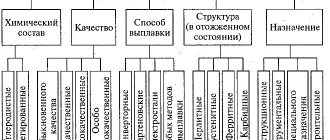
General information about steels
All of them have chemical and mechanical properties. Below we’ll talk in more detail about ways to increase strength, but first, let’s present a diagram showing all the varieties:
Also watch a more detailed video:
All of them have chemical and mechanical properties. Below we’ll talk in more detail about ways to increase strength, but first, let’s present a diagram showing all the varieties:
Carbon
The higher the carbon content of a substance, the higher the hardness and the lower the ductility. But the composition should not contain more than 1% of the chemical component, since a larger amount leads to the opposite effect.
Manganese
A very useful additive, but with a mass fraction of no more than two percent. Mn is usually added to improve machinability. The material becomes more susceptible to forging and welding. This is due to the displacement of oxygen and sulfur.
Silicon
Effectively increases strength characteristics without affecting ductility. The maximum content is 0.6%, sometimes 0.1% is enough. Combines well with other impurities; together, they can increase corrosion resistance.
Nitrogen and oxygen
If they get into the alloy, but worsen its characteristics, they try to get rid of them during manufacturing.
Alloying Additives
You can also find the following impurities:
- Chrome – increases hardness.
- Molybdenum – protects against rust.
- Vanadium – for elasticity.
- Nickel – has a good effect on hardenability, but can lead to brittleness.
These and other chemicals must be used in strict proportions according to the formulas. In the article we talked about tensile strength (short-term resistance) - what it is and how to work with it. They also gave several tables that you can use while working. To finish, let's watch the video:
To clarify the information you are interested in, please contact our managers by phone;; 8 (800) 707-53-38. They will answer all your questions.