If we characterize the concept of yield strength briefly, then in the strength of materials the yield strength
is the stress at which plastic deformation begins to develop. Yield strength refers to strength characteristics.
According to [1], fluidity
is macroplastic deformation with very low
hardening
dτ/dγ.
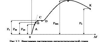
Physical yield strength
is a mechanical characteristic of materials: stress corresponding to the lower position
of the yield point
in
the tensile diagram
for materials having this site (figure),
σ
T =
P
T/
F
0. Here
P
T is the yield stress load, and
F
0 is the initial cross-sectional area of the sample.
Yield strength
establishes the boundary between the elastic and elastic-plastic deformation zones.
Even a small increase in stress (load) above the yield point
causes significant deformation. [2]
Calculation of the yield strength value
The ingenious assumption Frenkel made in his calculations was that the process of changing the shape of the material was considered to be driven by shear stresses. For the onset of plastic deformation, it was assumed that it was sufficient for one half of the body to move relative to the other to such an extent that it could not return to its initial position under the influence of elastic forces.
Physical Yield Strength Graph
Frenkel suggested that the material tested in the thought experiment has a crystalline or polycrystalline structure, characteristic of most metals, ceramics and many polymers. This structure presupposes the presence of a spatial lattice, in the nodes of which atoms are arranged in a strictly defined order. The configuration of this lattice is strictly individual for each substance, as are the interatomic distances and the forces connecting these atoms. Thus, in order to cause plastic shear deformation, it will be necessary to break all interatomic bonds passing through the conventional plane separating the halves of the body.
At a certain stress value equal to the yield stress, the bonds between atoms from different halves of the body will break, and a number of atoms will shift relative to each other by one interatomic distance without the possibility of returning to their original position. With continued exposure, such a microshift will continue until all the atoms of one half of the body lose contact with the atoms of the other half
In the macrocosm, this will cause plastic deformation, change the shape of the body and, with continued exposure, lead to its destruction. In practice, the line of the beginning of destruction does not pass through the middle of the physical body, but is located in the locations of material inhomogeneities.
General information and characteristics of steels
Steel refers to a malleable wrought alloy based on iron with carbon and additives of other elements. The material is smelted from cast iron mixtures with metal scrap in open-hearth, electric and oxygen converter furnaces.
Equilibrium state in the structure of steels
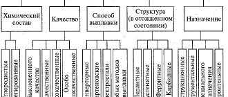
The formed crystal lattice of the metal depends on the amount of carbon contained in them and is determined by the structural diagram in accordance with the processes in this alloy. For example, a steel lattice, which contains up to 0.06% carbon, has a granular structure and is ferrite in its pure form. The strength of such metals is low, but the material has a high limit of impact strength and fluidity. The structures of steels in a state of equilibrium are divided into:
- ferritic;
- pearlite-ferritic;
- cementite-ferritic;
- cementite-pearlite;
- pearlite;
Influence of carbon content on the properties of steels
Changes in the main components of cementite and ferrite are determined by the properties of the former according to the law of additivity. Increasing the percentage of carbon addition to 1.2% makes it possible to increase strength, hardness, the cold capacity threshold by 20ºC and the yield strength. An increase in carbon content changes the physical properties of the material, which sometimes leads to deterioration in technical characteristics, such as weldability and deformation during stamping. Low-carbon alloys have excellent welding properties in structures.
Manganese and silicon additives
Manganese is introduced into the alloy as a technological additive to increase the degree of deoxidation and reduce the harmful effects of sulfur impurities. In steels it is present in the form of solid components in an amount of no more than 0.8% and does not have a significant effect on the properties of the metal.
Silicon acts in the alloy in a similar way; it is added during the deoxidation process in an amount of no more than 0.38%. To be able to join parts by welding, the silicon content should not exceed 0.24%. Silicon in the alloy composition does not affect the properties of steels.
Impurities of sulfur and phosphorus
The limit for the sulfur content in the alloy is 0.06%; it is contained in the form of brittle sulfites. An increased impurity content significantly worsens the mechanical and physical properties of steels. This is reflected in a decrease in ductility, yield strength, impact strength, abrasion and corrosion resistance. The phosphorus content also worsens the quality characteristics of metal alloys; the yield strength after increasing phosphorus in the composition increases, but the viscosity and ductility decreases. The standard impurity content in the alloy is regulated in the range from 0.025 to 0.044%. Phosphorus most strongly deteriorates the properties of steels with a simultaneous high level of carbon additions.
Nitrogen and oxygen in the alloy
These substances contaminate steel with non-metallic impurities and worsen its mechanical and physical properties. In particular, this applies to the threshold of viscosity and endurance, ductility and brittleness. An oxygen content in the alloy of more than 0.03% causes rapid aging of the metal, nitrogen increases fragility and increases strain aging over time. The nitrogen content increases strength, thereby lowering the yield strength.
Alloying additives in alloys
Alloyed steels include steels into which elements are specially introduced in certain combinations to improve quality characteristics. Complex alloying gives the best results. Chromium, nickel, molybdenum, tungsten, vanadium, titanium and others are used as additives.
Alloying increases the yield strength and other technological properties, such as impact strength, narrowing and the possibility of calcination, reducing the threshold for deformation and cracking.
Influence of carbon content on the properties of steels
According to the physicochemical principle of additivity, the change in the physical properties of materials is determined by the percentage of carbon. Increasing its proportion to 1.2% makes it possible to increase the strength, hardness, yield strength and threshold cold capacity of the alloy. A further increase in the proportion of carbon leads to a noticeable decrease in technical indicators such as weldability and ultimate deformation during stamping operations. Low carbon steels exhibit the best weldability.
Strength limits of materials
Quick search
A certain threshold value for a specific material, exceeding which will lead to the destruction of the object under the influence of mechanical stress. The main types of strength limits: static, dynamic, compressive and tensile. For example, the tensile strength is the limit value of a constant (static limit) or variable (dynamic limit) mechanical stress, exceeding which will rupture (or unacceptably deform) the product. Unit of measurement - Pascal, N/mm² = .
Yield strength (σt)
The amount of mechanical stress at which the deformation continues to increase without increasing the load; used for calculating permissible stresses in plastic materials.
After passing the yield point, irreversible changes are observed in the metal structure: the crystal lattice is rearranged, and significant plastic deformations appear. At the same time, self-strengthening of the metal occurs and after the yield point, the deformation increases with increasing tensile force.
This parameter is often defined as “the stress at which plastic deformation begins to develop,” thus identifying the limits of yield and elasticity. However, it should be understood that these are two different parameters. The yield strength values exceed the elastic limit by approximately 5%.
Endurance limit or fatigue limit (σR)
The ability of a material to withstand loads that cause cyclic stress. This strength parameter is defined as the maximum stress in a cycle at which fatigue failure of the product does not occur after an indefinitely large number of cyclic loads (the basic number of cycles for steel is Nb = 10 7). The coefficient R (σR) is taken to be equal to the cycle asymmetry coefficient. Therefore, the fatigue limit of the material in the case of symmetric loading cycles is designated as σ-1, and in the case of pulsating ones - as σ0.
Note that fatigue tests of products are very long and labor-intensive; they involve the analysis of large volumes of experimental data with an arbitrary number of cycles and a significant scatter of values. Therefore, special empirical formulas are most often used that connect the endurance limit with other strength parameters of the material. The most convenient parameter is considered to be the tensile strength.
For steels, the bending endurance limit is usually half the tensile strength: For high-strength steels, you can take:
For ordinary steels during torsion under conditions of cyclically changing stresses, the following can be accepted:
The above ratios should be used with caution, because they were obtained under specific loading conditions, i.e. during bending and torsion. However, when testing in tension-compression, the endurance limit becomes approximately 10-20% less than in bending.
Proportional limit (σ)
The maximum stress value for a particular material at which Hooke’s law still applies, i.e. body deformation is directly proportional to the applied load (force)
Please note that for many materials, reaching (but not exceeding!) the elastic limit leads to reversible (elastic) deformations, which, however, are no longer directly proportional to stress. Moreover, such deformations may “lag” somewhat behind the increase or decrease in load
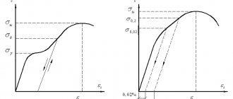
Diagram of the deformation of a metal sample under tension in the coordinates elongation (Є) - stress (σ).
1: Absolute elasticity limit.
2: Limit of proportionality.
3: Elastic limit.
4: Yield strength. (σ 0.2)
www.smalley.ru
Limit - strength - steel
This is almost twice the tensile strength of steel 3; the rod will fail much earlier than the critical voltage is reached. As we can see, with small flexibility, Euler's formula gives exaggerated values of critical stresses and critical forces.
The influence of corrosion increases with increasing tensile strength of steel. In Fig. Figure 9 shows the dependence of the endurance limits of laboratory samples on the tensile strength of steel for various corrosive environments. Analysis of the graphs shows that the endurance limit under corrosion conditions does not depend on the tensile strength of the steel, as a result of which the use of alloy steels when operating a part in a corrosive environment is impractical. The endurance limit is also significantly reduced in the case when the samples are subjected to corrosion before the fatigue test for several days, after which they are tested for fatigue without exposure to the environment.
As can be seen from the curve, the tensile strength of steel decreases with increasing test time.
As the carbon content increases, the steel's tensile strength, hardness and brittleness increase, while the elongation and toughness decrease. The weldability of steel deteriorates with increasing carbon content.
The previous analysis shows that the tensile strength of steel has a dominant influence on the fatigue limit in the presence of stress concentration. It turns out that other factors, such as hot working, steel composition and quality, have very little additional influence compared to the influence of tensile strength. It is interesting to know what value of tensile strength would provide maximum endurance in the presence of stress concentration. The relationships given above show that there is a continuous, albeit small, increase in the endurance limit under conditions of stress concentration with increasing tensile strength.
There is an opinion that the product of the tensile strength of steel and its relative contraction can be considered as the endurance limit. When checking the influence of this indicator on the wear resistance of steel during impact-abrasive wear, different dependencies were also obtained in the brittle and ductile fracture regions. With a uniform increase in the product aBty, the wear resistance of steel in the brittle fracture region increases, and in the ductile region it decreases.
According to numerous data, the coefficients of variation in the tensile strength of steels O0B range from 3 to 12%, and the distribution of OB values over the set of all heats corresponds quite well to the normal law.
| Comparison of hardness and tensile strength of armored iron and steel with 0 3p / o C at. |
A certain relationship has been established with a sufficient degree of accuracy between the Brinell hardness number and the tensile strength of steel for testing at room temperature.
According to the work and others, the tensile strength of steel decreases slightly when unloaded samples absorb hydrogen. The results of our tests, described in Chapter V, showed a significant decrease in the tensile strength of steel as a result of hydrogenation of samples without load in hydrogen sulfide solutions.
| Mechanical properties of chromium-nickel steels with silicon. |
At an annealing temperature above 980 C, the tensile strength of steel 27 - 4 - Mo increases, and the impact strength decreases sharply, which is explained by the formation of acicular austenite during cooling. At 760 C, the impact strength decreases as a result of the formation of the og phase.
| Dependence of Ke and Ke on temperature for alloy steel (17, Kavg. |
With decreasing temperature, the yield strength and tensile strength of steel increase, and 0T increases more intensely, so that the ratio at / sgv tends to unity when the temperature decreases to – 180 C.
According to the work and others, the tensile strength of steel decreases slightly when unloaded samples absorb hydrogen. The results of our tests, described in Chapter V, showed a significant decrease in the tensile strength of steel as a result of hydrogenation of samples without load in hydrogen sulfide solutions.
Manganese and silicon additives
An alloying additive in the form of manganese is used to deoxidize the alloy and compensate for the negative effects of harmful sulfur-containing impurities. Due to its similar properties to iron, manganese does not have a significant independent effect on the properties of the alloy. Typical manganese content is about 0.8%.
Silicon has a similar effect; it is added during the deoxidation process in a volume fraction not exceeding 0.4%. Since silicon significantly worsens such a technical indicator as the weldability of steel. For structural steels intended for welding, its proportion should not exceed 0.25%. Silicon does not affect the properties of steel alloys.
Pipe yield strength
The most obvious influence of this value is during the construction of pipelines for high-pressure systems. In such structures, special steel should be used, which has sufficiently large yield strengths, as well as minimal gaps between this parameter and the tensile strength. The higher the steel limit, the higher, naturally, the permissible operating voltage should be. This fact has a direct impact on the strength of steel, and accordingly, the entire structure as a whole.
Due to the fact that the parameter of the permissible design value of the stress system has a direct impact on the required value of the wall thickness in the pipes used, it is important to calculate as accurately as possible the strength characteristics of the steel that will be used in the manufacture of pipes. One of the most authentic methods for determining these parameters is to conduct research on a discontinuous sample
In all cases, it is necessary to take into account the difference between the values of the indicator under consideration, on the one hand, and the permissible stress values, on the other.
In addition, you should know that the yield strength of a metal is always established as a result of detailed repeated measurements. But the system of permissible stresses is overwhelmingly adopted based on standards or generally as a result of technical specifications, as well as based on the personal experience of the manufacturer. In main pipeline systems, the entire regulatory collection is described in SNiP II-45-75. So, setting the safety factor is a rather complex and very important practical task. The correct determination of this parameter entirely depends on the accuracy of the calculated values of stress, load, and the yield strength of the material.
When choosing thermal insulation for pipeline systems, they also rely on this indicator. This is due to the fact that these materials directly come into contact with the metal base of the pipe, and, accordingly, can take part in electrochemical processes that adversely affect the condition of the pipeline.
What is PT for valves?
These products are an integral part of reinforced concrete, intended, as a rule, to resist tensile forces. Usually steel reinforcement is used, but there are exceptions. These products must work together with the mass of concrete at all stages of loading a given structure without exception, and have plastic and durable properties. And also meet all the conditions for the industrialization of these types of work. The mechanical properties of steel used in the manufacture of reinforcement are established by the relevant GOST and technical specifications. GOST 5781-61 provides for four classes of these products. The first three are intended for conventional structures, as well as non-prestressed rods in prestressed systems. The yield strength of reinforcement, depending on the class of the product, can reach 6000 kg/cm2. So, for the first class this parameter is approximately 500 kg/cm2, for the second – 3000 kg/cm2, for the third – 4000 kg/cm2, and for the fourth – 6000 kg/cm2.
Hardness Determination
Hardness characterizes the resistance of a material to large plastic deformations. The most common methods for determining hardness involve the introduction of a special body - an indenter
, into the test material, with such force that an indenter imprint remains in the material. The value of hardness is judged by the imprint.
Hardness is the most common method for determining the properties of a material. This is due to a number of reasons: hardness determinations are a non-destructive method, because the part after such measurement can be used for its intended purpose; hardness tests do not require high qualifications and, in addition, knowing the hardness, one can judge other mechanical properties.
Brinell method.
A hardened steel ball is used as an indenter, which is pressed into the test sample using a special press; as a result, an imprint in the form of a spherical hole is formed on the surface of the sample. Hardness values are the ratio of the applied load to the surface area of the indentation. They are calculated by the formula: HB=2P/D(D-(D2-d2) 1/2). Here HB is the designation of hardness (for example, 200HB); P – applied load; D and d are the diameters of the ball and imprint.
In practice, they use a table that shows hardness values depending on the diameter of the print.
The Brinell method is not universal. It does not allow testing materials with a hardness of more than 450HB, because in this case, the indenter - the ball, as well as samples with a thickness of less than 1...2 mm can be deformed due to their punching.
The following approximate relationships are observed between the Brinell hardness and the tensile strength of different materials: for steel sв=НВ/3, st=НВ/6; for aluminum alloys; sв=0.362НВ; for copper alloys sв=0.26НВ.
Rockwell method.
The fundamental difference between this method and the one discussed earlier is that the hardness is determined not by the surface area of the indenter imprint, but by the depth of its penetration into the sample under study.
A diamond cone is used as an indenter when testing hard materials and a hardened steel ball when testing soft materials. The load when using a diamond cone is set to 150 or 60 kgf depending on the hardness of the material - greater for less hard materials (for example, hardened steel); smaller for materials with very high hardness (carbide alloys, cutting ceramics) to avoid chipping the diamond cone. The steel ball is pressed with a load of 100 kgf.
Tests are performed on a special device that has two scales - black and red. The black scale is used when testing with a diamond cone, the red scale is used when testing with a hardened steel ball. Hardness designations: HRC – diamond cone, load 150 kgf (64HRC), HRA – diamond cone, load 60 kgf (90HRA), HRB – ball, load 100 kgf (120HRB).
Hardness values in HRC units are approximately 10 times less than in HB units. Those. a hardness of 30 HRC approximately corresponds to 300HB. There is the following relationship between the hardness values on the “C” and “A” scales: HRC=2HRA-102.
Vickers method.
The method is based on indentation of a tetrahedral diamond pyramid with an angle between opposite faces equal to 136°. Hardness (denoted HV, for example, 1000HV) is determined by the ratio of load and surface area of the print. Hardness values are calculated using the formula: HV=1.854 R/d2, where d is the average length of the imprint diagonals.
The load can vary from 1 to 100 kgf. The size of the diagonals is determined using a special microscope built into the device.
Determination of impact strength.
Different materials react differently to an external force applied to them, causing a change in their shape and linear dimensions. This change is called plastic deformation. If the body, after the cessation of the impact, independently restores its original shape and linear dimensions, such deformation is called elastic. Elasticity, viscosity, strength and hardness are the main mechanical characteristics of solid and amorphous bodies and determine the changes that occur with a physical body during deformation under the influence of external force and its limiting case - destruction. The yield strength of a material is the value of stress (or force per unit cross-sectional area) at which plastic deformation begins.
Impurities of sulfur and phosphorus
Sulfur is an extremely harmful impurity and negatively affects many physical properties and technical characteristics.
The maximum permissible content of this element in the form of brittle sulfites is 0.06%
Sulfur impairs the ductility, yield strength, impact strength, wear resistance and corrosion resistance of materials.
Phosphorus has a dual effect on the physical and mechanical properties of steels. On the one hand, with an increase in its content, the yield strength increases, but on the other hand, viscosity and fluidity simultaneously decrease. Typically the phosphorus content ranges from 0.025 to 0.044%. Phosphorus has a particularly strong negative effect with a simultaneous increase in the volume fraction of carbon.
Composition of steel alloys
The properties of the metal depend on the formed crystal lattice, which, in turn, is determined by the carbon content. The dependence of lattice types on the amount of carbon is clearly visible in the structure diagram. If, for example, there is up to 0.06% carbon in the steel lattice, then this is classic ferrite, which has a granular structure. This material is fragile, but fluid and has a high impact strength limit.
According to the structure of steel, they are divided into:
- ferritic;
- pearlite-ferrite;
- cementite-ferritic;
- cementite-perlite;
- pearlite
Carbon Additives and Strength
The law of additivity is confirmed by the percentage changes in cementite and ferrite in steel. If the amount of carbon additive is about 1.2%, the yield strength of the steel material is increased and the hardness, strength and temperature resistance are improved. With a subsequent increase in carbon content, the technical parameters deteriorate. Steel is difficult to weld and is difficult to stamp. Alloys with a low carbon content behave best when welding.
Manganese and silicon
Manganese is additionally added as an additive to increase the degree of deoxidation. In addition, this element reduces the harmful effects of sulfur. The manganese content is usually no more than 0.8% and it does not affect the technological properties of the alloy. Present as a solid component.
Silicon also does not particularly affect the characteristics of the metal. It is necessary to increase the quality of welding parts. The content of this element does not exceed 0.38% and it is added during the deoxidation process.
Sulfur and phosphorus
Sulfur is contained in the form of brittle sulfites. An increased amount of this element affects the mechanical properties of the alloy. The more sulfur, the worse the ductility, fluidity and viscosity of the alloy. If the 0.06% limit is exceeded, the product is more susceptible to corrosion and becomes susceptible to severe abrasion.
The presence of phosphorus increases the fluidity index, but at the same time the plasticity and viscosity decreases. In general, an excessive phosphorus content significantly deteriorates the quality of the metal. The combined high content of phosphorus and carbon has a particularly harmful effect on the characteristics. Acceptable limits for phosphorus content are considered to be values from 0.025 to 0.044%.
Nitrogen and oxygen
These are non-metallic impurities that reduce the mechanical properties of the alloy. If the oxygen content is more than 0.03%, then the metal ages faster, and the values of ductility and viscosity decrease. Nitrogen additives increase strength, but in this case the yield strength decreases. The increased nitrogen content makes steel brittle and contributes to the rapid aging of the metal structure.
Behavior of alloying additives
To improve all the physical characteristics of steel, special alloying elements are added to the alloy. Such additives can be tungsten, molybdenum, nickel, chromium, titanium and vanadium. Joint addition in the required proportions gives the most acceptable results.
Nitrogen and oxygen in the alloy
These non-metals from the beginning of the periodic table are harmful impurities and reduce the mechanical and physical characteristics of steel, such as the viscosity threshold, ductility and brittleness. If oxygen is contained in amounts greater than 0.03%, this leads to accelerated aging of the alloy, and nitrogen increases the fragility of the material. On the other hand, the nitrogen content increases strength by reducing the yield strength.
Microstructure of an alloy containing nitrogen and oxygen
PT calculation
In strength of materials, the yield stress is the stress at which plastic deformation begins to develop. Let's look at how this value is calculated. In experiments carried out with cylindrical samples, the value of the normal stress in the cross section at the moment of occurrence of irreversible deformation is determined. Using the same method, in experiments with torsion of tubular samples, the shear yield strength is determined. For most materials, this indicator is determined by the formula σТ=τs√3. In some specimens, continuous elongation of a cylindrical sample on the diagram of the dependence of normal stresses on relative elongation leads to the detection of a so-called yield tooth, that is, a sharp decrease in stress before the formation of plastic deformation.
Moreover, a further increase in such distortion to a certain value occurs at a constant voltage, which is called physical DC. If the yield area (horizontal section of the graph) is large, then such a material is called ideally plastic. If the diagram does not have a platform, then the samples are called hardening. In this case, it is impossible to accurately indicate the value at which plastic deformation will occur.
Tensile strength
Let's look at how this characteristic of mechanical properties is determined. Strength is the ability of a material, under certain limits and conditions, to withstand various impacts without collapsing. Mechanical properties are usually determined using conventional stress-strain diagrams. Standard samples should be used for testing. Test instruments are equipped with a device that records the diagram. Increasing loads above normal causes significant plastic deformation in the product. The yield strength and tensile strength correspond to the highest load preceding the complete destruction of the sample. In plastic materials, deformation is concentrated in one area where a local narrowing of the cross section appears. It is also called the neck. As a result of the development of multiple slips, a high dislocation density is formed in the material, and so-called nucleation discontinuities also arise. Due to their enlargement, pores appear in the sample. Merging with each other, they form cracks that propagate transversely to the tensile axis. And at a critical moment the sample is completely destroyed.
GOST and DIN standards for high-strength fasteners
Today, “high-strength” comes to the market from domestic, European and Asian manufacturers. And if the quality of Chinese fasteners causes distrust among consumers, then Russian and European products are in great demand. Many foreign DIN and EN standards stipulate the use of bolt sets (bolt, nut, washer assembly) from one manufacturer. There are no such rules in our documents. They also do not have requirements for the type of protective coating, whereas European hardware is usually hot-dip galvanized.
Table 2. Standards for high-strength fasteners in Russia and Europe.
| National standards of the Russian Federation | European standards |
| GOST R 52643-2006 General technical conditions | DIN EN 14399-1:2006 General requirements |
| GOST R 52644-2006 (ISO 7411:1987) Bolts | DIN EN 14399-2:2006 Testing suitability for pretensioning |
| GOST R 52645-2006 (ISO 4775:1984) Nuts | DIN EN 14399-4:2006 Assemblies of bolts and nuts. HV system |
| GOST R 52646-2006 (ISO 7415:1984) Washers | DIN EN 14399-5:2006 Washers |
| DIN EN 14399-6:2006 Beveled washers |
The main types of high-strength bolts, screws and studs used in Russia by construction companies and engineering enterprises:
GOST 52644, GOST 22353, DIN 6914, ISO 7412
The listed standards apply to high-strength hex bolts (HSB), designed for use in the installation of structural steel structures, as well as in bridge construction and heavy engineering to create highly loaded connections. The size range is limited to diameters M16 – M48. Available in climatic versions “U” and “HL”
GOST 7798, GOST 7805, DIN 933, DIN 931, ISO 4014, ISO 4017
Standards for BVP with normal hex head, full and partial thread, used for fastening parts and structural elements in the automotive industry and other manufacturing and construction fields. They have a wide range of diameters from M3 to M64. They are produced uncoated or galvanized using different methods (galvanic, thermal diffusion, hot). Analogues with fine threads - DIN 960, DIN 961.
DIN 912, DIN 6912, GOST 11738, ISO 4762
These standards produce hex socket and cylinder head screws that are used in a wide range of industries. DIN and ISO screws have a longer list of sizes and are produced only in high strength classes 8.8, 10.9, 12.9, while GOST allows their production in low classes, but with a limited diameter from M3 to M36.
DIN 444, GOST 3033-79
These standards describe the requirements for eye screws (bolts) with metric threads with a diameter of M5 to M36, which are used in machine tools, as a connection part in mechanical engineering or in conjunction with construction anchors with internal threads.
DIN 975, DIN 976
These standards regulate the dimensions, length, pitch and type of thread of threaded rods (rods). High-strength studs include studs with a strength limit of 800...1200 Nm. They have a fixed length of 1000 or 2000 mm, diameter from M4 to M48. They are used in mechanical engineering, the construction industry, and for the installation of cable and pipe racks.
All of the above hardware are manufactured in black (for painting) and galvanized in various ways.
Metal fluidity
Knowledge of the mechanical properties of a material is extremely important for the designer who uses them in his work. It determines the maximum load on a particular part or the structure as a whole, if exceeded, plastic deformation will begin, and the structure will lose its strength, shape and may be destroyed.
Destruction or serious deformation of building structures or elements of transport systems can lead to large-scale destruction, material losses and even casualties.
The yield strength is the maximum load that can be applied to a structure without deformation and subsequent failure. The higher its value, the greater the load the structure can withstand.
Metal fluidity
In practice, the yield strength of a metal determines the performance of the material itself and products made from it under extreme loads. People have always predicted the maximum loads that the structures they erect or the mechanisms they create can withstand. In the early stages of industry development, this was determined experimentally, and only in the 19th century did the creation of the theory of strength of materials begin. The issue of reliability was solved by creating a multiple safety margin, which led to heavier and more expensive structures. Today it is not necessary to create a model of a product of a certain scale or full size and conduct experiments on destruction under load on it - computer programs of the CAE (calculation engineering) family can accurately calculate the strength parameters of the finished product and predict the maximum load values.
Steel testing
To fully study the properties of the material and determine the yield strength, plastic deformation and strength, metal samples are tested until complete destruction. The test is carried out under the action of loads of the following type:
- static load;
- cyclic category (endurance or fatigue);
- stretching;
- bend;
- torsion;
- less often to combined loads, for example, bending and tension.
Determination of test load limits is carried out under standard conditions, using special machines, which are described in the rules of State standards.
Testing a sample to determine the yield strength
To do this, take a cylindrical sample with a size of 20 mm and a calculated length of 10 mm and apply a tensile load to it. The concept of effective length refers to the distance between the marks marked on a longer sample to allow for gripping. To carry out the test, the relationship between the increase in tensile force and the elongation of the test piece is determined. All test readings are automatically displayed as a graph for easy comparison. It is called a conditional tension or conditional stress diagram; the graph depends on the initial cross-section of the sample and its initial length. Initially, an increase in force leads to a proportional elongation of the sample. This provision applies up to the limit of proportionality.
After reaching this threshold, the graph becomes curvilinear and indicates a disproportionate increase in length with a uniform increase in load. Next comes the determination of the yield strength. As long as the stresses in the sample do not exceed this indicator, the material can return to its original state in terms of size and shape when the load is removed. In practical testing, the difference between these limits is small and not worth much attention.
Yield strength
If you continue to increase the load, then a test moment comes when the change in shape and size continues without increasing force. In the diagram this is shown by the horizontal straight line (platform) of yield. The maximum stress at which the deformation increases is recorded after the load stops increasing. This indicator is called the yield strength. For steel Art. 3 yield strength from 2450 kg per square centimeter.
Proof of Yield
Many metals, when tested, give a diagram in which the yield plateau is absent or poorly expressed; for them the concept of conditional yield strength is used. This concept defines the stress that causes permanent change or deformation within the limit of 0.2%. Metals to which the concept of conditional yield strength is applied are alloyed and high-carbon steels, bronze, duralumin and others. The more ductile the steel, the greater the indication of residual deformation. These include aluminum, brass, copper and low-carbon steels. Tests of steel samples show that the fluidity of the metal causes significant shifts of crystals in the lattice, and is characterized by the appearance on the surface of lines directed towards the central axis of the cylinder.
Tensile strength
After a change by a certain amount, the sample transitions to a new phase, when, after overcoming the yield point, the metal can again resist stretching. This is characterized by hardening, and the line of the diagram rises again, although the rise occurs in a more gradual manner. Temporary resistance to constant load appears.
After reaching the maximum stress (ultimate strength), a sharp narrowing area appears on the sample, the so-called neck, characterized by a decrease in the cross-sectional area, and the sample breaks at the thinnest point. In this case, the voltage value drops sharply, and the magnitude of the force also decreases.
Steel St.3 is characterized by a tensile strength of 4000–5000 kg/cm2. For high-strength metals, this figure reaches a limit of 17500 kg/cm3.
Plasticity of the material
It is characterized by two indicators:
- residual relative elongation;
- residual narrowing at rupture.
To determine the first indicator, the total length of the stretched sample after rupture is measured. To do this, fold the two halves together. Having measured the length, calculate the percentage of the original length. Strong alloys are less susceptible to ductility and the elongation rate is reduced to 63 et 11%.
The second characteristic is calculated after measuring the narrowest part of the fracture and is calculated as a percentage of the original cut area of the sample.