Babbitt: disadvantages and alternatives. Repair of plain bearings.
Surprisingly, it is discovered that in an era of widespread access to information and ease of obtaining knowledge, some important industries or individual processes remain at a level of development more than 100 years ago, although existing competencies and experience in this area make it possible to make a significant technological breakthrough without making much effort .
This applies, for example, to the technology of restoration and repair of plain bearings in rotary equipment.
The technology for filling bearings is widely known and described in detail. The first bearing alloy called Babbitt was developed by the American Isaac Babbitt in 1839, and from 1847 to this day Babbitt of different chemical compositions has been used in industrial production in Russia. Over the past 180 years, the world has long learned to synthesize substances with predetermined special properties that are best suited for specific tasks. However, it is difficult to explain the continued commitment of many mechanics and engineers to obsolete technology and material, while much better solutions are being used everywhere.
It becomes obvious that the use of modern materials and the replacement of ineffective technologies is an irreversible trend. Repair and maintenance companies using outdated technologies will inevitably be displaced by more efficient competitors. The task of a qualified specialist is to make the right choice and try to take leadership in this movement!
Below is an overview of those negative factors that are forgotten when using babbitt as a repair material for plain bearings. These factors significantly outweigh the usual statements of conservative mechanics that it is easy and convenient to work with babbitt, repairs are cheap and quick, there are many specialists who know the technology, the material is not difficult to buy, etc.
If you already feel the need to abandon babbitt and the outdated technology for filling it, but do not know about a possible alternative, then you can immediately go here and get acquainted with modern technologies for the manufacture and repair of plain bearings.
If such a failure is not obvious to you, then our materials will prove to be a convenient guide to the operation of plain bearings based on Babbitt alloys.
1. The danger of filling sliding bearings with babbitt.
2. Problems during work execution.
3. General disadvantages of plain bearings based on babbitt alloys.
4. Malfunctions and damage to plain bearings.
Danger of filling sliding bearings with babbitt.
The table provides information about substances that are hazardous to humans when working with during the production and repair of plain bearings using Babbitt.
| № | Name | Danger | Consequences for humans |
| Substances included in the composition | |||
| 1 | Lead 64-85% (grades B16, BN, BS6) | Hazard class 1 Heavy metal, tends to accumulate in the body. Even a small dose, but systematically entering the body, leads to concentration of the substance. | The substance affects several systems: Central nervous system – irritability, insomnia, increased excitability, disturbances in brain activity. In acute poisoning, loss of consciousness. Neurological disorders and mental disorders are observed. In severe cases, encephalopathy develops (organic brain damage resulting from the death of brain cells). Urinary system - kidney function is disrupted, fluid is not removed from the body in full. A person develops hypertension. Damage to tubules and glomeruli. Progressive chronic renal failure develops. Peripheral nervous system – paralysis of the hand or foot. Skeletal system – with prolonged exposure, lead accumulates in the bones and leads to osteomalacia (softening of the bones). |
| 2 | Antimony 5.5-17% (grades B88, B83, B83S, B16, BN, BS6) | Hazard class 1 Toxic substance, enters the body through the respiratory system | A severe degree of poisoning is dangerous due to the development of collapse due to paralysis of blood vessels. Chronic forms of poisoning lead to the development of liver cirrhosis, anemia, myocardial damage, pathology of reproductive function, and acute gastroenteritis. Vomiting, diarrhea, and acute pain in the abdominal area are observed. Hemorrhagic gastritis, ulcerative lesions of the stomach and intestines, inflammation of the pancreas develop |
| 3 | Arsenic 0.05-0.9% (grades B88, B83, B83S, B16, BN, BS6) | Hazard class 1 Chronic poisoning occurs with prolonged exposure to small doses in an industrial environment containing waste products and contamination, | It manifests itself as erythroderma, hyperkeratosis, hyperpigmentation, scaly dermatitis, and respiratory diseases often occur - laryngitis, tracheitis, bronchitis. Long-term exposure to small doses of arsenic provokes cancer. |
| 4 | Heavy elements: cadmium, bismuth 0.1-1.2% | Hazard class 1 Inhalation of metal particles at work contributes to the development of lung cancer. | Blocking of sulfur-containing amino acids, which leads to disruption of protein metabolism and damage to the cell nucleus. They promote the removal of calcium from bones and affect the nervous system. They accumulate in the kidneys and liver and are excreted from the body very slowly. |
| Used in production work | |||
| 5 | Hydrochloric acid | Hazard class 1 Inhalation of mist and vapors is dangerous. | Causes severe burns upon contact with skin. Contact with eyes is especially dangerous. Fog and vapors formed when concentrated acid interacts with air are very dangerous. They irritate the mucous membranes and respiratory tract. Prolonged work in the atmosphere causes catarrh of the respiratory tract, tooth decay, clouding of the cornea of the eyes, ulceration of the nasal mucosa, and gastrointestinal disorders. Acute poisoning is accompanied by hoarseness, suffocation, runny nose, and cough. |
| 6 | Sulfuric acid | Hazard class 1 Inhalation of vapors, contact with skin and mucous membranes | Inhalation of vapors can lead to irritation and subsequent damage to internal organs. Signs: sudden darkening of some parts of the body, irritation of the mucous membranes, nosebleeds, pain in the esophagus. A burn to the throat can cause painful spasms that make breathing difficult. |
| 7 | Sodium hydroxide | Hazard class 2 Ingestion. Corrodes skin and mucous membranes upon direct contact. | Causes a painful syndrome in the epigastric region, a burning sensation in the gastrointestinal tract, up to anaphylactic shock. |
| 8 | Zinc chloride | Hazard class 2 Toxic. Dangerous if it enters the respiratory tract or mucous membranes. | Causes irritation; with prolonged contact with the skin, it causes burns and corrodes tissue. The resulting wounds are very difficult to heal. In small doses it causes soreness in the nasopharynx and throat, and a dry cough. Inhalation of large amounts of chloride may cause shortness of breath and so-called wheezing. If the substance gets into the mucous membrane of the eye, intense cutting pain may occur, complete or partial blindness may occur. |
| 9 | Ammonium chloride | Hazard class 3 Dangerous if inhaled or ingested in large quantities | Inhaling too much of its vapor can lead to cardiac arrest. Inhaling large amounts of vapor is extremely dangerous, as it can cause burns to the respiratory tract and respiratory arrest. An overdose of ammonium salt solution causes unpleasant symptoms of poisoning: nausea, vomiting and loss of appetite. |
TOP
Problems during work execution.
When performing work on pouring babbitt, the following problems most often occur:
- Low quality raw materials. Production of raw materials from melted scrap with burnt-out alloying elements.
- High cost of monitoring compliance of the chemical composition of raw materials with GOST.
- High costs for auxiliary work.
- Working with toxic and harmful substances.
- The need to equip a special base or production site with personal and industrial protective equipment.
- Large material losses and production waste.
- Frequent formation of shells and other defects leading to defective products.
- Burnout of alloying elements due to overheating or incorrect cooling mode.
- Internal defects that are revealed only during finishing.
centrifugal filling method used has disadvantages:
- The need for special machines.
- The need for special forms of increased strength and tightness.
- The need for specially trained personnel.
- Manual production of work.
- Lack of automatic control of the production process.
- Liquation (stratification) of alloy components by density.
- The result of segregation is the concentration of alloying components either in the outer layers, removed during the finishing process, or at the steel base.
- Unsatisfactory babbitt structure due to segregation.
TOP
General disadvantages of plain bearings based on babbitt alloys
- All babbitts have a significant drawback - low fatigue resistance, which impairs the performance of the bearing, especially when operated under conditions of frequent heating and cooling cycles (start/stop or changing operating modes).
- Chipping.
- Low vibration resistance due to misalignment or unbalancing of rotors, pinching of bearing chairs, unsatisfactory filling of liners and for other reasons.
- Critical sensitivity to lubrication conditions, oil quality, oil pump operation, etc.
- High failure rate. For an accident to occur, a short-term drop in oil pressure and the occurrence of melting or destruction of the babbitt after 4-5 rotor revolutions (tenths of a second at 3000 rpm) are sufficient.
- Significant losses and loads due to dry friction (during the start-up period, especially of heavy rotors).
- Large axial clearances for guaranteed oil wedge maintenance.
- High lubrication costs to ensure heat removal and maintain temperature conditions.
TOP
Damage to Babbitt bearings.
Due to the poor compliance of Babbitt with modern requirements for equipment operation, there are numerous causes of damage to plain bearings. Below is a list of the most critical damage to production.
| Corrosion | Metal fatigue | Thermal faceting |
| Intergranular cracking | Cavitation | Electric discharge |
| Fretting - corrosion | Lack or loss of lubrication | Damage from foreign substances or dirt |
| Overload | Overheat | Loss of clearance at startup |
| Misalignment, skew, imbalance | High starting loads |
TOP
Corrosion
Under normal conditions, lubricating oils do not attack bearing materials. However, there are some unfavorable circumstances under which corrosion may occur. Corrosion of lead-based babbitt can be caused by acidic oil oxidation products formed during operation, the ingress of water or coolant into the lubricating oil, and the decomposition of certain oil additives. Hydrogen sulfide in oil is affected by tin. This exposure to hydrogen sulfide causes the copper-tin compound in the lining to deplete, weakening the material.
Figure 1: Corrosion of a white metal coated marine turbine bearing; the water in the oil caused a smooth, hard black deposit of tin dioxide to form on the surface
Rice. 2: Sulfur corrosion of small diameter phosphor bronze bushing caused by decomposition of lubricating oil additive and destruction of bearing surface
Rice.
3: Severely corroded copper-lead bearing surface caused by acidic oil oxidation products. TOP
Metal fatigue
Metal fatigue occurs as a result of dynamic loads that exceed the fatigue strength of the bearing material at operating temperature. Fatigue strength is significantly reduced at high temperatures, especially for low melting point materials such as babbitt; therefore, overheating alone can cause fatigue damage. Other causes include overloading, cyclic unbalanced loading due to overspeed, and shafts that are not truly cylindrical due to manufacturing defects. Fatigue cracks typically coalesce to form pits with a characteristic rounded "molten" appearance.
Figure 4: Upper half of a babbitt-lined, chambered turbine bearing showing fatigue cracking due to unbalanced load and excessively wide cut
Rice. 5: Fatigue cracking of a babbitt-lined bearing due to shaft deflection and edge loading
Fig.6: Fatigue cracking of a babbitt-lined bearing due to shaft rib caused by differential wear in a 180° groove
TOP
Thermal faceting
Thermal faceting only affects tin-based babbitt. Tin crystals are anisotropic and have different coefficients of thermal expansion on each crystal axis. Repeated thermal cycling results in faceting of the bearing surface, which in the worst case can cause waviness in excess of 0.025 mm. In rare cases, cracks may form between the grains.
Fig. 7: Thermal faceting due to thermal cycles in the extreme operating temperature range
Rice. 8: Faceting on babbitt material due to thermal cycles.
TOP
Intergranular cracking
In high-speed turbomachinery bearings, the combination of high surface temperatures and high shear rates can result in the formation of a network of intergranular cracks in the hottest region of the bearing. Excessive lead content in tin babbitt can exacerbate this problem.
Rice. 9: A support bearing from a large steam turbine, covered in white metal, with intergranular cracks of a typically “loose” appearance.
TOP
Cavitation
In addition to the requirements of viscous fluid and relative motion, hydrodynamic bearings require a tapered geometry to create oil wedge pressure to resist the load. After passing the zone of minimum film thickness, the gap between the bearing and the shaft increases; The change in clearance can be either gradual or sudden. When the lubricant rapidly expands, steam bubbles can form and collapse, causing cavitation erosion damage in the babbitt. Inward explosions create craters and cracks in the babbitt, and in some, corrosion extends below the surface. Figure 10 shows cavitation damage at the outer diameter edge of the thrust pad. Part of the damage is shown at higher magnification in Figure 11. Typically, cavitation damage involves a large area of the thrust pad.
Rice. 10. Cavitation damage to the thrust block
Rice. 11. Scanning electron micrograph of cavitation damage at the edge of the thrust block shown in Figure 10.
The harder the bearing material, the less likely it is to experience cavitation erosion. Polymers and ceramics are less susceptible to cavitation damage. There are no documented cases of cavitation erosion in polymers or ceramics.
In internal combustion engines, cavitation erosion is the severe effect of fatigue corrosion caused by the formation and collapse of vapor bubbles in the oil film under conditions of rapid pressure changes during the crank cycle.
Rice. 12. Diesel engine main bearing set showing cavitation wear of the soft cover while the hard aluminum housing is unaffected
Rice. 13. Cavitation erosion of a bearing coated with white steel is downstream of the bearing surface and groove in the other half.
TOP
Electric discharge
During operation, an electrical charge may accumulate on the shaft. Sources of this charge can come from residual magnetic fields on the shaft, alternating electromechanical fields, stray shaft currents, or static electricity that accumulates from the wet stages of a steam turbine. When the electrical potential is sufficient, the charge will be grounded through the path of least electrical resistance. Because wet film bearings operate with very thin films of lubricant, an arc will often pass from the shaft to the housing through the bearing if it is not protected. When the charge actually jumps across the gap between the bearing and the rotor, the babbitt material is vaporized by the arc. The resulting depressions are typically hemispherical and shiny, giving a matte appearance to the damaged area. There is usually no protruding material around the depressions, as can occur with embedded particles. Damage often begins at an area of minimum film thickness and then increases in size as material is removed, resulting in a sharp boundary between the damaged and undamaged surface areas. If the electrical arc continues, a large portion of the surface may be subject to spark erosion and the substrate material may be exposed. As a rule, similar damage also appears on the rotating part. Figures 14 and 15 show pads that have been damaged by electrical discharge. Note the clear transition from the undamaged area to the matte area of the pad. Part of the pad damage area in Figure 14 is shown under magnification in Figure 16. Figure 17 shows a microphotograph of one of the electrical discharge depressions.
In addition to, or instead of, bearing insulation, polymer-coated pads can be used to prevent the charge from traveling to ground.
Figure 14. Support block damaged due to electrical discharge.
Rice. 15. Support block damaged due to electrical discharge.
Fig. 16. Enlarged section of the block in Figure 14.
Rice. 17. Microphotograph of a “depression” from an electrical discharge; smooth features are visible under magnification.
TOP
Fretting - corrosion
Bearing running surfaces can suffer from fretting corrosion when the shaft is at rest due to vibrations transmitted to the machine from external sources, such as another machine nearby. Ship technology is particularly susceptible to this problem. If the machine is started after fretting corrosion, the hard black residue can cause scoring and hide the original fretting damage. Similar damage can occur when transporting machines if the shaft is not secured.
Fig.18: Surface damage caused by external rotation when the shaft is not rotating
Rice. 19: Turntable and hemispherical cavities caused by fretting due to vibration
TOP
Lack or loss of lubrication
Fluid dynamic bearings rely on a layer of lubricant to separate rotating and stationary parts. As a rule, mineral or synthetic oil is used as a lubricant in a turbomachine. Process fluids such as water, toluene and refrigerant are also increasingly used as bearing lubricants. In addition to providing the necessary fluid for film formation, the lubricant is also used to conduct heat away from the bearing. When lubrication is interrupted momentarily or for an extended period of time, the hydrodynamic film does not form or is insufficient to support the shaft or thrust plate, contact between rotating and stationary parts can occur. Even if the lack of lubrication does not result in contact, the cooling effect will be incomplete, resulting in overheating of the supporting material. Thrust pads and support shoes damaged due to insufficient lubrication are shown in Figures 20 and 21.
Rice. 20. Abrasion of the thrust pad due to lack of lubrication.
Rice. 21. Abrasion of the support pad due to an immediate decrease in oil flow.
Damage to bearing surfaces often resembles damage caused by overload. Bearing surfaces may appear as if they are overheated by oil varnish appearing on the surfaces. An interesting form of abrasion is observed if the oil supply was momentarily interrupted due to a decrease in flow from the oil pump, instantly losing performance or power. The babbitt on the surface of the support block reached a temperature sufficient to melt, but quickly cooled, forming a thin foil of babbitt on the support blocks. Figure 22 shows a bearing block that was damaged by a momentary interruption of oil flow to the bearing. During the repair of the damaged support block, a thin foil of Babbitt (shown in Figure 23) was removed from the bearing. Damage to this support block was attributed to an accidental reduction in lubricant flow from the main lubrication pump due to a drop in electrical power from the pump motor.
Rice. 22. Erasure of the support block due to an immediate decrease in oil flow.
Rice. 23. Thin babbitt foil removed from the support block in Figure 22.
Polymer bearings can operate with reduced lubrication during short-term failures.
TOP
Damage from foreign substances or dirt
Foreign matter or dirt entering turbomachinery bearings is a common source of damage to thrust and journal bearings in all types of turbomachinery. Dirt may be present at start-up if housings, shafts, oil lines, lubrication passages and bearings are not prepared before assembly and start-up of the unit. In addition, dirt can enter the bearing through lubricant that has become contaminated either from external sources through breathers and air filters, or from wear particles from other components during operation. The abrasive particle marks on startup when the rotation speed is low are irregular and the particles appear to roll across the bearing surface. Rice. Figure 24 is a photograph of a thrust pad that was damaged by abrasive particles during startup. If abrasive particles enter the bearing during operation when the speed is higher, the damage to the bearing surface will be consistent patterns such as concentric tracks in the shoe, as shown in Fig. 25. Visual inspection and particle testing can help identify sources of contamination, such as rotor or seal wear.
Rice. 24. Damage due to abrasive particles during startup.
Rice. 25. Damage due to abrasive particles during operation.
At the end of the mark, the abrasive particle may become embedded in the babbitt, resulting in the formation of craters or raised areas around the embedded abrasive particle, as shown in Figure 26. Polymer coatings are capable of absorbing abrasive particles (foreign particles). A thrust block with a polymer layer and with absorbed metal particles is shown in Fig. 27.
Rice. 26. “Craters” of embedded particles.
Rice. 27. Polymer coated thrust pad with display of absorbed metal particles.
One type of abrasive wear that causes serious damage to bearings and shafts with babbitt pads is “scuffing.” Scouring occurs when a relatively large particle hits the babbitt. The particle can react with the shaft material and form a hard deposit on the pad, commonly known as black cake (Fig. 29). The solid residue causes severe damage to the mating surface, acting as a cutting tool, then this damage spreads to the point where the shaft and bearing stop working. In Fig. Figure 28 shows a shaft with a damaged support journal. A thrust block with damage in the form of a “black crust” is shown in Fig. 29. Shafts and thrust plates containing more than 1.3% chromium are susceptible to scoring. Additionally, some oil additive packages increase the chances of scuffing.
Rice. 28. Seizure of the shaft support journal.
Rice. 29. “Black crust” on the thrust block.
TOP
Overload
Fluid dynamic bearings rely on a thin layer of lubricant that separates the rotating shaft from the plain bearing. When the load exceeds the film's load-bearing capacity, contact between the rotating and stationary surfaces occurs. Contact leads to an increase in the temperature of the babbitt layer of the bearing, which, in turn, can lead to overheating or even local melting. Thrust pads that were worn out due to overload are shown in Fig. 30. Babbitt was moved from one area to another in the direction of rotation. The analysis usually reveals changes in the grain structure in the damaged layer of base material.
Rice. 30. Worn thrust pads due to overload.
TOP
Overheat
As the lubricant passes through the bearing gap, it is subjected to friction, resulting in high temperatures. This heat is mostly carried away by the lubricant, but some of it is transferred to the bearing. Operating bearings at high temperatures continues to be a common cause of damage. High temperature can be caused by various mechanisms such as high loads, high lubricant inlet temperatures, high speed and insufficient lubrication (“oil starvation”). Blackened area on the thrust pad ("oil coking"), as shown in Fig. 31, is a consequence of high temperature.
Babbitt is an anisotropic material with different coefficients of thermal expansion along different axes of the crystal lattice. Thermal cycles over large temperature ranges can result in a mottled (faceted) appearance of the bearing surface or, if the temperature is too high, intergranular cracking of the babbitt due to its anisotropic nature. As a rule, the cut shown in Fig. 32, is not a defect, but distinguishes different grains in the babbitt structure. However, high temperature differences can lead to intergranular cracking. Babbitt is subject to shear and normal forces, potentially opening cracks. A thrust block with intergranular cracking is shown in Fig. 33.
The yield strength of babbitt falls rapidly with increasing temperature, which can lead to a condition where the actual local pressure exceeds the yield strength of babbitt at the local temperature. The bearing surface has a wavy appearance, as shown in Figure 34, due to the babbitt flowing under high pressure and temperature. It is possible that the babbit will continue to flow over the edge of the thrust block, as shown in Figure 31.
Rice. 31. Coking on the thrust block due to high temperature.
Rice. 32. Faceted thrust block due to thermal cycling.
In particular, another source of potential damage to turbine bearings is latent heat in the shaft or housing that enters the bearing after the rotor stops. Heat penetration from the shaft or housing may be sufficient to melt the babbitt if the cooling lubricant is not maintained. Figure 35 shows a support bearing where the babbitt has melted due to heat leaking from the turbine housing into the bearing. When the availability of cooling lubricant cannot be guaranteed, babbitt can be replaced with a material that can withstand higher temperatures but also has good bearing characteristics. Engineered polymers can be used as an alternative to babbitt to combat potential damage due to heat penetration.
Rice. 33. Intercrystalline corrosion on the thrust pad due to high temperature.
Rice. 34. Thrust block with deformed surface due to exceeding the yield strength
Rice. 35. Babbitt support bearing damaged by heat penetration.
TOP
Loss of clearance at startup
The clearance between the bearing surface and the shaft in journal bearings is often designed to minimum tolerances to achieve specific bearing characteristics. During fast starts on cold machines, such as in engine-driven gas compressors, the small bearing clearance may be lost as the shaft and pads expand rapidly, but the bearing housing and unit housing do not. The friction of the lubricant in the film is a source of heat for thermal growth. However, the bearing housing and unit housing do not expand as quickly as the pads and shaft due to the relatively large thermal mass and poor heat transfer from the pads to the housing. As the shaft expands due to temperature and the pads, which are confined to the housing, expand due to thermal growth inward, the clearance between the pads and the shaft decreases briefly. As the clearance decreases, all the pads come into contact with the shaft, causing wear on all the pads around the bearing. If the loss of clearance is severe enough, the rotor may seize. Support pads worn down the center are shown in Figure 36, 37. This type of damage occurs during startup and is not necessarily accompanied by dynamic vibrations.
Rice. 36. Erasure of support pads due to lack of clearance during startup.
Rice. 37. High dynamic load of all pads.
Rice. 38. Minimum bearing clearance as a function of speed.
TOP
Misalignment, skew, imbalance
With both thrust and journal bearings, misalignment between the shaft and bearing can cause excessive localized loads over a small area, resulting in damage due to high pressure and temperature. Damage manifests itself as discoloration, abrasion, or cracking of the bearing surfaces, depending on localized pressure and temperature. Again, the damage is similar to other types of damage such as overloading, but the wear pattern due to misalignment is usually uneven. In journal bearings, damage occurs toward the axial end of one or more pads. In thrust bearings, the pad group on one side of the thrust bearing becomes damaged. Figure 39 shows pads that were damaged due to the high local temperature and pressure that resulted from the misalignment. Misalignment could be caused by poor machining of the bearing seats in the housing, improper installation, or contamination between the bearing and housing.
In addition to damaging the bearing surface, misalignment can cause damage to the supporting structure where the joint contacts the bearing housing or the bearing contacts the unit housing. As with damage to the Babbitt surface, the wear pattern of bearing components is uneven.
Rice. 39. Damage to the thrust bearing due to misalignment.
TOP
High starting loads
Until speeds sufficient for hydrodynamic film development are achieved, the stationary and rotating bearing components are in contact, initially without any lubrication between the contacting surfaces (boundary lubrication) and then with little lubrication between the surfaces (mixed lubrication). Contact between surfaces causes polishing of the bearing material and can ultimately lead to wear of the bearing material. Once the material is removed, the bearing no longer performs as designed. Many types of turbomachinery can have high startup loads. Pillow bearings on large gas and steam turbines are often subject to high loads (due to the weight of the rotor) during startup. Thrust bearings in vertical pumps and hydraulic turbines often have to support the weight of the rotor, motor and impellers. Another example of a machine with a high starting load is a multi-shaft gas compressor, where the line pressure at start-up can result in a high load on the normally balanced thrust bearing. Figures 40 and 41 show a thrust and support block that were damaged due to excessive loading during starting and stopping. Note the thin layers of babbitt that accumulate on the edge of the pads due to successive starts and stops under excessive load.
Rice. 40. Erasure of the thrust block due to high load at start-up.
Rice. 41. Erasure of the support block due to high load at start-up.
(Figure 42 shows a damaged thrust bearing.)
Rice. 42. Damaged thrust bearing after a lubrication system failure.
TOP
Babbitt bearings
?The compressor Arty obtained turned out to have one crankshaft bearing completely crushed :(, so we were puzzled by the restoration of this monster. First we had to get a babbitt, we were very lucky with this, a good uncle - the seller was inspired by our stories about restoring ancient cars and gave (! ) two tiles of wonderful babbitt B - 83. Respect and respect to the uncle Here is what this mysterious babbitt is like: Two pieces weighing 1.7 kg. To pour the babbitt, a ladle of a cunning design was made (the babbitt must be whipped from the bottom so that it flows without an oxide film). This is where a tube is welded into the scoop, reaching to the bottom. The small ancient fire extinguisher said goodbye to the lower part of its body without regret. The groove is small so that the tube stands at the required angle. A lid is cut out from a piece of steel 4 mm thick and a piece of half-inch pipe is determined. And finally, that’s all this is welded and ground so that it burns less.Now that the physical base is prepared, we need to figure out how to cast these bearings. Their figure is very spicific, slopes, sides. It’s good that the bearing on the second connecting rod is intact and can be measured: after measurements and fittings, the following set of pieces of iron was machined: And when assembled, it looks like this (on the connecting rod without a bearing). All the necessary cavities are formed, you can fill: The central bushing is temporary, you need to make it aluminum, otherwise everything will be soldered to death. About pouring into the print. times, because haven't tried yet.
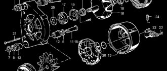
The main installation for flame wire spraying was developed by M.U. Schoop in 1913. The speed of the combustion products of acetylene in oxygen was 10:12 m/s. The density of metal spraying is 85 - 90% of the compact material. An oxygen-acetylene flame was used as a heat source. In modern times, substitutes for acetylene have become widely used for metal spraying: propane, ethylene, methane, hydrogen. rice. Wire atomizer diagram: 1 - air nozzle; 2 - gas nozzle; 3 - rod; 4 - guide tube.
Production and restoration of babbitt bearings by flame spraying of babbitt. Sputtering of bronze, brass, sprababbit is a guarantee of high quality anti-friction layer. The production and remanufacturing of babbitt bearings is usually accomplished by pouring molten babbitt. The disadvantages of the technology provided are also quite familiar - the subtle risk of detachment of the babbitt layer, the appearance of cavities or solid inclusions in the babbitt layer. The listed production risks often call into question the very use of babbitt as an antifriction material.
Production and restoration of babbitt bearings by flame spraying of babbitt. Sputtering of bronze, brass, sprababbit is a guarantee of high quality anti-friction layer. The production and remanufacturing of babbitt bearings is usually accomplished by pouring molten babbitt. The disadvantages of the technology provided are also quite familiar - the subtle risk of detachment of the babbitt layer, the appearance of cavities or solid inclusions in the babbitt layer. The listed production risks often call into question the very use of babbitt as an antifriction material.
Babbitt is a special anti-friction alloy based on tin or lead, most often used to fill bearing shells. The excellent anti-friction qualities of babbitt are associated with its special heterogeneous structure, which is characterized by the presence of hard particles in the soft plastic base of the alloy. This type, tin or lead, is a plastic alloy base, which ensures uniform fit and running-in of the bearing to the shaft. The alloy also contains strong inclusions that serve as support for the bearing, ensuring it has low friction and wear. Certain brands of Babbitt contain additives such as antimony, copper, nickel, arsenic, cadmium, tellurium, calcium, sodium, magnesium, etc. Babbitt has a low melting point within 300 - 440°C, as well as good workability.
The chemical composition and brands of babbitts must comply with GOST standards. For tin and lead babbits there is GOST 1320 - 74, for calcium - GOST 1209 - 90. Depending on the chemical composition, the following brands of babbits are distinguished: B88, B83, B83S - tin babbits, B16, BN and BS6 - lead babbits. Depending on the composition of babbitts, their scope of application is determined. Thus, lead Babbitt B-16 is used for motor-axial bearings of electric locomotives and road vehicles; parts of steam locomotives and other heavy engineering equipment that are subject to heavy loads. Tin babbits B - 83, 88 are primarily used in bearings, which are made at high speeds and normal loads; for example, turbine bearings, crosshead, crank and frame bearings of low-speed diesel engines, support bearings of ridge shafts.
Related posts:
- Pouring bearings
- Plain bearing shells
- Technological process…
- Bearing shell
- Bearing grease…
https://rsute.ru expensive pens as a gift for a man.
Machining of bearing shells consisting of two halves
Fig. 618. Planing halves of bearings on a longitudinal planing machine, several pieces at a time.
Processing of liners consisting of two halves is divided into two parts: 1) before filling and 2) after filling with babbitt.
Processing of the halves begins at the joint surface of the liners; processing is usually carried out by milling on a vertical milling machine or by planing several pieces on a longitudinal planing machine (Fig. 618). Processing on cross-planing and surface grinding machines is carried out less frequently.
In case of insufficient processing accuracy on milling or planing machines, the joint planes are scraped after this operation.
After processing the butt plane, the liners can be processed using two methods:
1) first turning the outer surface of the liners or
2) first boring the inner surface.
Processing according to the first method is carried out on a central mandrel (Fig. 619), on which half of the liner is attached with two strips. In such a mandrel, the middle outer surface of the liner is pre-ground.
Fig. 619. Center mandrel for turning insert halves.
The disadvantage of this device is the possibility of uneven clamping of the liner by the strips, which can cause distortion, damage and deformation. With this method, a lot of time is spent on installation
products. Another disadvantage is that the cutter only works on a semicircle.
The next processing operation for the liner is boring the hole and turning the sides; these operations are carried out in the chuck shown in Fig. 620.
Fig. 620. Chuck for boring liners.
Centering of the liner is carried out along the outer turned diameter using the lower half of the cartridge and the upper removable one. Both devices must first be balanced.
The main disadvantage of this method should be considered that the processing is not carried out according to the general rule - from the hole to the outer surface, but vice versa; but in view of the fact that these operations are pre-treatment for filling with babbitt, this method can be considered acceptable.
It is advisable to bore the hole before turning in order to identify defects in the casting.
Sometimes the sides are first turned, after which the middle outer surface is turned using spindle mandrels, that is, mandrels inserted into the spindle hole. The latter option is more often used for small-sized inserts.
The second method - boring the hole after processing the butt planes - is done either in a self-centering chuck or in a special device (Fig. 621).
Fig. 621. Device for boring the liner.
In this device, the installation is carried out first of the upper half of the liner on special tides a (Fig. 622); the upper half of the liner is pressed with bolt B to planes A and C (Fig. 621).
Fig. 622. Inserts with special bosses (a).
In the horizontal direction, the liner is fixed with protrusion C.
After securing the upper half, the lower half is inserted under the upper between the strips A, which fix the position in the horizontal direction, after which the lower half is secured with bolt D.
The hole bored in this chuck ensures an exact fit of the connector along the axis of the liner, which is not always achieved in a self-centering chuck.
The well-known method of soldering two halves with subsequent processing of the liner as a whole has recently begun to be replaced by the methods described above due to the fact that soldering is an unnecessary operation and, most importantly, that it can introduce inaccuracy due to
uneven thickness of the solder layer; In addition, not all metals can be soldered well.
Fig. 623. Processing of liner beads on a special mandrel.
Additional heating of the liners to separate them is often undesirable and unacceptable when the liners are filled with babbitt.
In view of these disadvantages of soldering, the most rational way is to tighten the halves with clamps.
After boring the liners, the beads are trimmed and turned on a special mandrel (Fig. 623), on which the liners are centered by a split sleeve moving from nut A, and secured with clamp B.
Turning of the outer surface is carried out on the same mandrel (Fig. 624).
Fig. 624. Processing the outer surface of the liners on a special mandrel.
Without removing the clamp B, tighten the split bushing with nut A and clamp the liners with two washers C, after which the clamp is removed and the outer diameter is turned.
Large liners are usually bored on rotary machines. When filling large liners with babbitt, for better fastening of the babbitt. they are machined and grooved in the form of a dovetail.
After boring and turning, the liners are sent to be filled with babbitt.
Before pouring babbitt, surfaces are first cleaned of dirt and rust, degreased, tinned and then filled with molten babbitt.
Fig. 625. Filling one half of the liner with babbitt.
Before pouring, cast iron liners are etched with a weak solution of sulfuric or hydrochloric acid and washed in warm running water; then they are degreased in a solution of caustic soda or ammonia, after which poluda is produced.
The pouring is done mostly in the vertical direction, one half at a time in a special form (Fig. 625) or both halves are poured together in a device, as shown in Fig. 626.
Fig. 626. A simple device for filling bearing shells.
Pouring using the ascending jet method with gradual overturning of the ladle (Fig. 627) results in better quality due to the presence of pressure from a hot column of metal. The disadvantage of the latter method is the high consumption of babbitt.
Currently, the centrifugal pouring method is widely used, the advantage of which is the uniform thickness of the resulting babbitt layer, as a result of which it is possible to reduce the processing allowance to 2 mm.
Fig. 627. Filling the liner with an ascending jet.
An important advantage of this method is also the fast filling with low consumption of babbitt compared to manual filling.
Since the installation for pouring babbitt takes up little space, it can be located between machines, in this case using electric furnaces for melting babbitt.
The installation diagram is shown in Fig. 628.
Fig. 628. Installation diagram for centrifugal filling of bearings with babbitt.
Recently, pressure casting has been widely used in special machines.
Pouring is done with metal coming from a reservoir under the pressure of a piston, which is moved manually using a handle or handwheel.
The reservoir is constantly heated by a gas burner or an electric coil. This method produces good quality filling.
Fig.629. Cleaning the planes of the connector of the liner on a vertical milling machine.
After pouring, the connector planes are cleaned on a vertical milling machine (Fig. 629), after which the lubrication holes are drilled using a special device (Fig. 630) and holes are drilled for the control pins along the conductor (Fig. 631), which is sometimes done before filling the liners with babbitt.
Next comes finishing boring and turning of the liners, which is carried out similarly to the preliminary operations.
Fig. 630. Drilling lubrication holes in liners using a special device.
Fig. 631. Drilling holes for control pins.
Processing of so-called refrigerators (bevels at the parting plane) can be done on a lathe and boring machine (Fig. 632), as well as on a horizontal milling machine (Fig. 633).
Fig. 632 Processing of the “refrigerator” of the liners on a boring machine.
The lubrication grooves of the liners in single small-scale production are cut out by mechanics, in medium and large-scale production they are processed on milling machines (Fig. 634), but more often on special lathes with reciprocating movement of the caliper using a copier or crank mechanism.
Fig. 633. Processing of refrigerators at the liners on a horizontal milling machine.
Fig. 634. Milling lubrication grooves for liners.
In fig. 635 shows a lathe-type machine for cutting lubrication grooves with a crank mechanism, which has the ability to change the stroke length.
Door A closes the crank mechanism. Finishing of the outer surface of the liner is limited to turning, and only sometimes grinding is performed.
Finishing of the internal surface in small- and medium-scale production is usually limited to boring and manual scraping or reaming.
Small liners are sometimes flared after final boring.
In fig. 636 shows the rolling for liners.
Fig. 635. Machine for cutting lubrication grooves.
In medium and large-scale production, hole piercing is often used, as well as diamond boring on special machines, which differ from fine boring in that the process is carried out at high speeds; Thus, for cast iron with a cutting depth of 0.05–0.10 mm and a feed of 0.03–0.06 mm, cutting speeds are 150–200 m/min, for bronze – 200–400 m/min and for babbitt up to 1000 m /min.
Diamond boring is done with diamond cutters, but recently cutters are used exclusively from hard alloys Tina Pobedit-alpha-21, RE-18, etc.
Currently, automobile factories are beginning to use liners made of steel tape 1-2 mm thick, which is coated with a thin layer of babbitt and cut into pieces; heated pieces are bent in presses, inserted into the product and pulled or unfolded.
With this method, large savings in babbitt are obtained.
Fig. 636. Rolling for liner.