Classification and thread parameters
Threads are classified according to the following characteristics:
- according to the profile of the screw surface: triangular, trapezoidal, thrust;
- according to the shape of the surface on which the thread is made: cylindrical and conical, external and internal;
- in the direction of the screw movement of the threaded contour: right and left;
- by number of passes: single- and multi-pass;
- by operational purpose: general use and special.
Threads for general use include:
- a) fastenings (metric, inch). The main requirement for them is to ensure the strength of the connection and maintain the tightness of the joint during long-term operation;
- b) kinematic (trapezoidal and rectangular) for lead screws. The main requirement for them is to ensure accurate movement with the least friction;
- c) pipe and fittings. The main requirement for them is to ensure tight connections.
Thrust threads are used to convert rotational motion into translational force (jacks, presses). The main requirement for it is to ensure high load capacity.
Thread parameters. In general mechanical engineering, metric threads are most widely used. GOST 24705-81 establishes the nominal profile of metric threads and the dimensions of profile elements.
d - outer diameter of the external thread (bolt); D —outer diameter of the internal thread (nut); d2 is the average diameter of the bolt; D2 - average diameter of the nut; d1 is the inner diameter of the bolt; D1 - internal diameter of the nut; d3 is the internal diameter of the bolt along the bottom of the cavity; P —profile pitch; H is the height of the original triangle; α = 60° – thread profile angle; R is the nominal radius of curvature of the bolt root;
The average diameter of the thread (d2, D2) is the diameter of an imaginary cylinder coaxial with the thread, the generatrix of which intersects the thread profile at the points where the width of the groove is equal to half the nominal thread pitch.
The outer diameter of the thread (d, D) is the diameter of an imaginary cylinder described around the tops of the external threads or the valleys of the internal threads.
The internal diameter of the thread (d1, D1) is the diameter of an imaginary cylinder inscribed tangentially to the recesses of the external thread or the crests of the internal thread.
Thread pitch (P) is the distance between adjacent profile sides of the same name in a direction parallel to the thread axis.
Thread profile angle (α) – the angle between the sides of the profile.
The height of the original profile (H) is the height of the acute-angled profile obtained by extending the sides of the profile until they intersect.
The working height of the profile is the height of contact between the sides of the profile of the external and internal threads in the direction perpendicular to the thread axis.
Make-up length (L) – the length of contact of the screw surfaces of external and internal threads in the axial section.
GOST 8724-81 sets thread diameters from 0.25 to 600 mm and pitches from 0.075 to 6 mm. There are 3 rows of metric thread diameters installed. When choosing a thread diameter, you should prefer the first row to the second, the second to the third.
Accuracy standards for threaded parts and connections
Table of contents:
Accuracy standards for threaded parts and connections
Threaded connection in accordance with GOST 11708-82 “Basic standards of interchangeability. Thread. Terms and definitions" is a connection of two parts using a thread, in which one of the parts has an external thread and the other has an internal thread.
Threaded connections are one of the most common types of connections. In mechanical engineering, about 80% of parts either have threaded surfaces or are fastened using threaded products.
The main advantages of threaded connections are:
- relatively easy assembly and disassembly;
- high level of interchangeability of fastening threaded products.
The disadvantages of threaded connections include the relative complexity of the design and technology (processing of threaded surfaces requires the use of special equipment and tools, and control of parts becomes more difficult).
Depending on the profile shape, threads are distinguished:
-metric (with a triangular profile, the initial one for which is an equilateral triangle, with an apex angle of 60°);
- inch (with a symmetrical triangular profile and apex angle of 55°), usually used for pipes (“pipe”);
- rectangular (with a rectangular profile);
- trapezoidal (with a symmetrical trapezoidal profile);
~ persistent (with an asymmetrical trapezoidal profile);
- round (with a profile formed by arcs).
In addition, threads designed for de. hoists made of certain materials, for example, for plastic parts, for ceramic parts, special threads for specific types of products, for example, eyepiece threads, etc.
Based on their functional purpose, a distinction should be made between dividing (“reading”) and power threaded connections. Per. They are designed to ensure high accuracy of linear and angular movements in measuring instruments and process equipment. Thus, in micrometric instruments, the main measuring transducer is a micro-metric screw-nut pair; in dividing machines, the main mechanism is also a screw-nut pair.
Power threaded connections are designed to create significant forces when moving parts (screws, presses, jacks) or to prevent mutual transfer! placement of connected parts (cover-body connections, threaded connections of pipeline parts, fastening of the bushing to the shaft, etc.). The division of threaded connections into “reference” and power connections is conditional and is carried out based on the main function of the mechanism, for example, the lead screw of a screw-cutting lathe must ensure high accuracy of movement under significant axial loads (“reference” connection).
Depending on the nature of the functioning, a distinction is made between fixed (fastening) and movable (kinematic) threaded connections. Movable threaded connections are formed through the use of clearance fits. In fixed connections, you can use all types of fits - interference fits, transitional fits and clearance fits. In order to ensure the immobility of a threaded connection when landing with a gap, either artificial methods are used to select gaps (up to the creation of interference in the connection), or additional structural elements are used that protect parts from self-unscrewing (lock washers, lock nuts, wire locks, sealants, etc.). ). It follows from this that in fixed threaded connections obtained using a clearance fit, after final assembly, interference is possible along the working sides of the thread profile while maintaining gaps on the opposite sides of the profile. In those threaded connections where transitional fits are used, interference is also created using special “jamming elements” (a flat collar or a cylindrical pin on a stud, or wedging along an incompletely cut thread profile).
In practice, metric threads are most widespread.
The metric thread profile is regulated by GOST 9150-2002 “Basic standards of interchangeability. Metric thread. Profile".
The thread profile is based on the original thread triangle (Fig. 3.98) with a profile angle of 60° and a height of .
The main parameters of metric threads include:
The average thread diameter is the diameter of an imaginary cylinder coaxial with the thread, the generatrix of which intersects the thread profile at the points where the width of the groove is equal to half the nominal thread pitch.
The outer diameter of a thread is the diameter of an imaginary cylinder described around the crests of an external thread or the root of an internal thread.
The internal diameter of a thread is the diameter of an imaginary cylinder inscribed tangentially to the valleys of an external thread or the crests of an internal thread.
Thread pitch is the distance between adjacent sides of the same name in a profile in a direction parallel to the thread axis.
Thread profile angle - the angle between the sides of the profile.
The angle of inclination of the side of the profile is the angle between the side of the profile and the perpendicular lowered from the top of the original profile of a symmetrical thread to the thread axis. By measuring the angle of inclination of the side of the profile, it is possible to establish thread misalignment resulting from inaccurate installation of the product or tool. It is impossible to determine thread misalignment based on the full angle.
The height of the original profile is the height of the acute-angled profile obtained by extending the sides of the profile until they intersect.
The working height of the profile is the height of contact between the sides of the profile of the external and internal threads in the direction perpendicular to the thread axis.
Make-up length is the length of contact of the screw surfaces of external and internal threads in the axial section.
GOST 8724-81 sets thread diameters from 0.25 to 600 mm and pitches from 0.075 to 6 mm. There are 3 rows of metric thread diameters installed. When choosing a thread diameter, the first row should be preferred to the second, and the second to the third.
For threads with fine pitches, different pitches can correspond to the same outer diameter.
The standardization of the accuracy of threaded surfaces can be considered using the example of metric threads intended for threaded connections with clearance, interference, and transitional fits.
To ensure make-up, the actual contours of the parts to be made, determined by the actual values of the diameters, angle and thread pitch, must not go beyond the limit contours along the entire make-up length.
Tolerance fields are assigned to the average diameter and the diameter of the thread protrusions, i.e. the outer diameter of the male thread and the internal diameter of the female thread. Only upper limit deviations are set for, and lower limit deviations for. The second deviations (“into the body of the part”) are not limited.
The main parameter of the threaded connection, which ensures the accuracy and nature of the connection, is the average diameter. The tolerance fields for the outer and inner diameters are constructed in such a way as to ensure a guaranteed gap.
The maximum deviations of the thread pitch and the angle of inclination of the side of the profile are normalized for threads intended for interference fits and transitional ones. For threads intended for clearance fits, these errors are not separately limited, since it is generally accepted that they are compensated by deviations in the average diameters of the bolt and nut.
The deviation of the thread pitch is the difference between the actual and nominal distance in the axial direction between two points of any of the same side sides of the profile (located at the line of intersection of the side surfaces of the thread with a cylinder of average diameter) within the make-up length or a given length.
Make-up without tension of threaded parts that have a thread pitch error is possible only if there is a positive difference in their diameters, obtained by reducing the average diameter of the bolt thread or increasing the average diameter of the nut thread:
The deviation of the angle of inclination of the side of the thread profile is the difference between the actual and nominal values. This error can be caused by an error in the full angle of the profile, an error in the position of the profile relative to the axis of the part. This error may result from errors in the profile of the thread-forming tool and inaccuracy in its installation.
Make-up without tension of threaded parts that have an error in the angle of inclination of the side of the profile is possible only if there is the required gap between the average diameters of the bolt and nut. Errors in the thread pitch and the angle of inclination of the side of the profile can be compensated by introducing the appropriate diametric compensations: - diametric compensation for the pitch error and - diametric compensation for the angle of inclination of the side of the profile. Diametric compensations can be carried out by reducing the average diameter of the bolt thread and/or increasing the average diameter of the nut thread. The value can be found from the triangle (Fig. 3.99, a). The value can be found from the triangle (Fig. 3.99, b). For metric thread
Dependencies for calculations make it possible to determine the effect of deviations on threaded parts in one (diametrical) direction and bring them to one parameter - the diameter of the thread. To simplify the control of threads and calculate tolerances on them, the concept of reduced average thread diameter has been introduced, taking into account the influence of parameter values on make-up
The average diameter of the thread, increased for the bolt and decreased for the nut by the total diametric compensation for deviations in the pitch and angle of inclination of the side of the profile, is called the reduced average diameter.
By the given average thread diameter we mean a certain conditional diameter that takes into account the errors in the pitch and the angle of inclination of the side of the profile.
The given average diameter of the external thread is determined as follows:
and the reduced average diameter of the internal thread
where and are the measured average diameters of the bolt and nut.
Total tolerance of mean thread diameter
The main parameters of threads (average diameter, pitch and profile angle) are interrelated, therefore the permissible deviations of these parameters of threaded surfaces intended for forming clearance fits are not standardized separately. The standard establishes only the total tolerance for the average diameter, i.e.
The total tolerance of the average diameter of the external thread is a tolerance, the upper limit of which limits the value of the given average diameter, and the lower limit limits the value of the actual average diameter. The total tolerance of the average diameter of the internal thread is a tolerance, the lower limit of which limits the value of the given average diameter, and the upper limit limits the value of the actual average diameter.
The total tolerance determines the position of two limit contours for a bolt thread and two limit contours for a nut thread.
The classification of threads by accuracy and fit is based on the tolerance of the average diameter and the nature of the mating on the sides of the profile.
Metric thread fitting system
All general purpose threads are connected along the side surfaces. The possibility of contact along the crests and valleys of the thread is eliminated by the appropriate arrangement of tolerance fields along the outer and inner diameters of the bolt and nut.
Depending on the nature of the connection on the side sides of the profile (or, as is commonly called, “along the average diameter”), threaded fits with clearance, interference fits, and transitional ones are distinguished. The fit of a threaded connection depends on the clearances or interference, which numerically represent the difference in the actual values of the given average diameters of the bolt and nut.
GOST 1609-81 “Clearance fits” establishes a tolerance system for threaded clearance fits.
The position of the thread diameter tolerance field (Fig. 3.100) is determined by the main deviation ( - for a bolt, - for a nut). The second maximum deviation is determined depending on the degree of accuracy established by the standard (Table 3.21).
There are five main deviations for external threads and four main deviations for internal threads (Fig. 3.101, 3.102). Deviations are measured from the nominal profile in the direction perpendicular to the thread axis.
For external and internal threads, in addition to degrees of accuracy, three accuracy classes are also established, conventionally called fine, medium and coarse, which include tolerances of the degrees of accuracy specified by the standard.
Precise class threads are recommended for critical statically loaded threaded connections. Medium accuracy class is recommended for general purpose threads. For non-critical threaded connections, a coarse accuracy class can be used. External threads of this class are cut on hot-rolled blanks, internal threads are cut in long blind holes. Threads of rough accuracy class are also produced by plastic deformation methods and other technological processes.
For fastening threads, threaded fits with increased guaranteed clearance are sometimes used, for example, in the following cases:
- for connections of parts operating at high temperatures (to compensate for temperature deformations, protect connections from jamming and enable the development of parts without damage);
- when it is necessary to ensure quick and easy screwing of parts (even if there is slight contamination or damage to the thread).
GOST 16093 also establishes three groups of make-up lengths: short, normal and long.
For the same accuracy class, it is recommended to increase the tolerance of the average thread diameter for the make-up length, and to reduce it by one degree of accuracy for the make-up length compared to the tolerances established for the make-up length.
The correspondence of the tolerance fields of external and internal threads to accuracy classes and make-up lengths is given in Table. 3.22.
The designation of the thread tolerance field consists of the designation of the tolerance field of the average diameter of the thread, placed in the first place, and the tolerance field of the diameter of the thread protrusions (outer diameter of the screw and inner diameter of the nut).
Thus, for an internal thread (nut), the tolerance fields are set for the average and internal diameters; for external threads (screws) - for the middle and outer diameters. For example, the designation indicates the tolerance range of the internal thread in diameter and the tolerance range of the internal thread in diameter.
If the designation of the tolerance field for the diameter of the protrusions coincides with the designation of the tolerance field for the average diameter, then it is not repeated in the general designation. For example, the designation is the tolerance fields of the external thread (screw) in diameter and .
The designation of the thread fit or the thread tolerance zone is written after the designation of the thread size, separated by a “dash” sign. The fit in a threaded connection is indicated by a fraction, the numerator of which indicates the designation of the tolerance fields of the internal thread, and the denominator - the external thread.
So, the designation means that the thread is metric, the nominal thread diameter is 12 mm; — tolerance range of internal thread (nut) along the average and internal diameters; — tolerance range of external thread (screw) along the middle and outer diameters. A large pitch in the thread designation may or may not be indicated, but a small pitch must be indicated with a numerical value in millimeters without a unit designation (for example,).
The absence of a tolerance field in the thread designation means that the accuracy standards are assigned to the “medium” class and this corresponds to the tolerance fields for external threads with nominal diameters up to 1.4 mm inclusive and for threads with nominal diameters 1.6 mm and more, and for internal thread tolerance fields for threads with nominal diameters up to 1.4 mm and for threads with nominal diameters 1.6 mm and more. However, such a designation is not desirable, since the preferred option includes designations of tolerance fields.
The normal make-up length is not indicated in the designation. Make-up lengths that differ from the normal one are indicated by the corresponding letters (for the group of make-up lengths: short - and long -), which are written after the designation of the thread tolerance field or the fit designation, separating it with a “dash” sign, for example, designation of an internal thread or threaded mating
After the letter indicating the make-up length, its value in millimeters can be placed in brackets without indicating units, for example,
When designating a multi-start metric thread, the letter , the nominal diameter of the thread, the letter and value of the thread stroke, the letter and value of the pitch are indicated. For example, the symbol for a two-start thread with a nominal diameter of 16 mm, a stroke of 3 mm and a pitch of 1.5 mm: or (two starts) -.
At the end of the left-hand thread designation, the letters are placed after the dash, for example
designation of internal left-hand metric thread with large pitch,
designation of internal left-hand metric thread with fine. step.
The designation of a multi-start left-hand metric thread is as follows:
where the nominal diameter is 16 mm, the thread stroke () 3 mm, the thread pitch () 1.5 mm, is the threaded fit and is the left-hand thread. ?
Threaded interference fits (GOST 4608-81) are provided for metric threads with diameters from 5 mm to 45 mm and pitches from 0.8 mm to 3 mm. These fits are designed for mating: external threaded parts (studs) made of steel, with threaded holes in parts made of steel, high-strength and titanium alloys, cast iron, aluminum and magnesium alloys.
To obtain threaded fits with an interference fit along the average diameter, the following tolerance fields are provided (Fig. 3.103): for internal threads (nuts) - , for external threads (screw) - , for diameters of internal thread projections - and for diameters of external thread projections - .
Interference fits along the average diameter of the thread are provided only in the main hole system.
Threaded interference fits are used in cases where it is necessary to ensure tightness or prevent self-unscrewing of studs under the influence of vibrations, variable loads and changes in operating temperature. An example is the fitting of stud threads into engine crankcases, car wheel hubs, etc.
If it is necessary to ensure a more uniform tension and increase the strength of connections, threaded parts are sorted by average diameter into groups, and then connections are assembled from groups of the same name (selective assembly). The standard provides for sorting threaded parts into two or three groups.
In threaded connections with interference along the outer and inner diameters of the thread, guaranteed clearances are provided to eliminate the possibility of jamming along these diameters during screwing.
For threaded surfaces of parts forming tension joints, the standard specifies the maximum deviations of the pitch and the angle of inclination of the side of the profile. In addition, since the quality of threaded connections with interference is affected by deviations in the shape of external and internal threads, they are also standardized. The standard normalizes the maximum shape deviation, determined by the difference between the largest and smallest actual average diameters, which should not exceed 25% of the average diameter tolerance. "Reverse taper" is not permitted.
Interference fits of steel studs into the body are selected depending on the material of the part with internal threads and the thread pitch (Table 3.23). If the designed mating differs from that recommended by the standard in terms of materials, pitch or make-up length, an additional check of the selected fit should be carried out.
An example of a designation for a threaded interference fit (material of a part with internal threads is steel, high-strength titanium alloys):
— metric thread, nominal thread diameter 16 mm; thread pitch - large (not indicated in the designation); — tolerance field of internal thread along the average diameter; — tolerance range of internal thread along the internal diameter; — tolerance field of external thread along the average diameter; The number of sorting groups (3 groups) is indicated in parentheses.
The tolerance fields of external threads on the outer diameter - (up to 1.25 mm) or (over 1.25 mm) are not indicated in the designation.
To form transitional threaded fits, GOST 24834-81 provides the following tolerance fields (Fig. 3.104): for internal threads (nuts) - ; for external thread (screw) -
In transitional fits, elements for jamming studs are additionally used: a conical thread run-out, a flat shoulder and a cylindrical pin at the end (for studs screwed into blind holes).
Options for transitional threaded fits, depending on the nominal diameter of the thread and the material of the part with internal threads, are given in Table. 3.24.
An example of a symbol for a threaded transition fit:
— metric thread with a nominal thread diameter of 16 mm; thread pitch - large (not indicated in the designation); — tolerance range of internal thread (nut) along the average diameter; — tolerance range of internal thread (nut) along the internal diameter; — tolerance range of external thread (screw) along the average diameter. The tolerance field of the external thread (screw) along the outer diameter is (not indicated in the designation).
Thread inspection methods and means
There are two methods for monitoring threaded surfaces: complex and differential (element-by-element).
Differential control of threaded surfaces - control of each of the standardized parameters with a separate conclusion on suitability for each of them. This method is used in cases where accuracy standards are specified for each individual thread parameter, for example, tolerance fields for the diameter of the protrusions and the actual average diameter, maximum deviations of the diameter of the recesses, as well as maximum deviations of the pitch and angle of inclination of the side of the profile are specified. This method is used when inspecting surfaces intended for threaded interference fits, surfaces of thread-forming tools and thread gauges.
For differential testing, such universal measuring instruments are used as measuring microscopes, projectors, three-coordinate measuring instruments or specialized thread measuring instruments, for example, thread micrometers, thread pedometers. In addition, to measure the average diameter of an external thread with one-dimensional universal measuring instruments, you can use auxiliary means - measuring wires that provide access to the side surface of the thread (the so-called “two-wire” and “three-wire” methods).
To control the parameters of internal threaded surfaces, access to which is significantly difficult, you can use replicas (casts or prints of part of the controlled surface) made from special low-shrinkage materials.
Differential control of thread parameters requires complex measuring instruments, highly qualified operator, it is labor-intensive and does not provide high labor productivity. However, information about the results of monitoring individual parameters allows you to make the necessary adjustments to the technological process of obtaining a threaded surface.
The complex method provides simultaneous control of several (or all) thread parameters by comparing the actual contour of the threaded part with the limit ones. The complex method is often used to control threaded parts, the tolerance field of the average diameter of which is “total” and is intended to normalize deviations of the average diameter itself and to compensate for deviations of the pitch and angle of inclination of the side of the profile that are not separately standardized.
The complex method is particularly implemented when inspecting threads using a thread gauge. The remaining gauges provide differentiated (element-by-element) control of thread parameters.
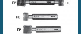
To control threaded parts, a set of gauges is used, which includes:
- threaded working gauges (PR and NOT); -smooth limiting calibers.
In addition, the complete set may also include control thread gauges and special installation gauges.
A thread pass gauge controls the possibility of screwing. It checks diameters, angles of inclination of the profile sides, pitch deviations, including its accumulated value over the length of make-up of the gauge with the controlled surface. In accordance with the Taylor principle, the working pass gauge must have a threaded surface of a full profile with a length equal to the make-up length. The screwability of the gauge with the inspected thread means that the obligatory condition for the suitability of the part is met, but another obligatory condition is the positive results of control with non-go gauges.
A no-go thread gauge only checks the actual mean diameter. To reduce the influence of errors in the angle of inclination of the profile and the pitch of the controlled thread on the make-up, no-go gauges have a shortened thread profile (to minimize the contact length of the sides of the thread profile) and a reduced number of turns (to eliminate the influence of the accumulated pitch error). When testing long threads, it is allowed to make up this gauge with the part being tested on the first two turns of the thread being tested. Screwing of a non-running thread gauge with short threads (up to three turns for a bolt and up to four for a nut) is not allowed.
To check the minimum material limit, limit smooth staples are used along the outer diameter of the bolt, and limit smooth plugs are used along the inner diameter of the nut.
The threads of working plug gauges are controlled by universal means. Working threaded ring gauges are checked with control gauges. Special control gauges are used to monitor the level of wear of rings in use. "Wear" gauges should not screw together with controlled gauges.
To adjust adjustable thread gauges, U-PR and U-NE installation plugs can be used, which are not included in the set of gauges and are manufactured to special order.
The caliber marking includes designations of the caliber, thread, degree of accuracy (for example, IIP, M12 - 6H) and the manufacturer's trademark.
This lecture is taken from the lectures page on standardization of accuracy:
Standardization of accuracy: course of lectures
Perhaps these pages will help you:
| Standardization of accuracy and fit of rolling bearings |
| Tolerances of angles and cones in metrology |
| Pin connections: designations and purpose |
| Keyed connections: designations and purpose |
Thread errors
The main thread errors are pitch incursion and profile angle distortion.
The error (deviation) of the DP step is the difference between the actual and nominal step sizes.
The pitch error consists of local and progressive pitch errors.
Local errors do not depend on the make-up length.
Progressive errors in the pitch of the cut thread arise in proportion to the number of turns along the make-up length.
The error (deviation) of half the thread profile angle Da/2 of a bolt or nut is the difference between the actual and nominal values Da/2.
The influence of deviations in diameters, pitches, and angle of inclination of the side of the profile on the strength of the thread and make-up.
In case of diameter deviations, the bolt and nut may not be screwed together. Deviation of the pitch in any direction worsens the make-up.
Cyclic strength depends on the uniform distribution of forces between turns. The presence of gaps along d2, d1 and d eliminates jamming of the turns, reduces friction between them and increases the compliance of the thread, compensating for manufacturing errors and evenly distributing the load between the turns.
With a progressive error and deviation of half the profile angle, the static strength of the thread decreases. Deviations of the pitch reduce the cyclic strength of the threaded connection, and deviations of the half angle of the profile increase it.
This is the result of the fact that a step error is rarely local. It is usually progressive, increasing in proportion to the number of complete steps along the make-up length (ΔPn).
An accumulated step error occurs:
- due to copying tap or die pitch errors;
- due to errors in the kinematics of the machine when cutting threads with a cutter using the machine feed box;
- due to wear of the lead screw and its temperature and force deformations;
- heterogeneity of the workpiece material and other reasons.
When manufacturing threaded parts, errors in the thread profile and its dimensions are inevitable, which can interfere with make-up and deteriorate the quality of the connections. To ensure make-up and quality of connections, the actual contours of the parts being made up should not exceed the limit contours along the entire make-up length.
The reduced average thread diameter is the average diameter of an imaginary ideal thread, which has the same pitch and flank angle as the main or nominal thread profile, and a length equal to the specified make-up length, which is in close contact (without mutual displacement or interference) with the real one. carvings on the sides of the threads.
Inch thread
BASIC PARAMETERS OF INCH THREADS (standards BSW (Ww), BSF, UNC, UNF)
The peaks and valleys of the inch thread profile, similar to the metric thread, are cut flat. The pitch of an inch thread is determined by the number of threads (turns) per inch 1′, but its apex angle is 55° (Whitworth thread - British standard BSW (Ww) and BSF), apex angle is 60° (American standard UNC and UNF ).
The outer diameter of the thread is measured in inches 1′ = 25.4 mm
— bar ( ' ) symbol of an inch.
Inch thread is characterized by the number of threads per inch. According to American standards, inch threads are made with coarse (UNC) and fine (UNF) pitch. NPSM
is an American standard for inch cylindrical pipe threads.
NPT
is an American standard for inch tapered threads.
Standards:
ASME/ANSI B1.1
– 2003 Unified Inch Screw Threads, UN & UNR Thread Form
ASME/ANSI B1.10M
– 2004 Unified Miniature Screw Threads
ASME/ANSI B1.15
– 1995 Unified Inch Screw Threads, UNJ Thread Form
AMERICAN INCH THREAD
Main parameters of inch threads:
d(D)
– outer diameter of the thread of the bolt and nut, respectively;
dp (Dp)
– average diameter of the thread of the bolt and nut, respectively;
di (Di)
– internal diameter of the thread of the bolt and nut, respectively;
n
– number of threads per inch.
American thread with coarse pitch - UNS
| Thread sizes , inches (mm) | n | D | Dp | Di | Thread sizes , inches (mm) | n | D | Dp | Di |
| inches | inches | ||||||||
| №1 (1,8542) | 64 | 0,0730 | 0,0629 | 0,0561 | |||||
| №2 (2,1844) | 56 | 0,0860 | 0,0744 | 0,0667 | 1 (25,4) | 8 | 1,0000 | 0,9188 | 0,8647 |
| №3 (2,5146) | 48 | 0,0990 | 0,0855 | 0,0764 | 1 1/8 (28,58) | 7 | 1,1250 | 1,0322 | 0,9704 |
| №4 (2,8448) | 40 | 0,1120 | 0,0958 | 0,0849 | 1 1/4 (31,75) | 7 | 1,2500 | 1,1572 | 1,0954 |
| №5 (3,1750) | 40 | 0,1250 | 0,1088 | 0,0979 | 1 3/8 (34,925) | 6 | 1,3750 | 1,2667 | 1,1946 |
| №6 (3,5052) | 32 | 0,1380 | 0,1177 | 0,1042 | 1 1/2 (38,10) | 6 | 1,5000 | 1,3917 | 1,3196 |
| №8 (4,1656) | 32 | 0,1640 | 0,1437 | 0,1302 | 1 3/4 (44,45) | 5 | 1,7500 | 1,6201 | 1,5335 |
| №10 (4,8260) | 24 | 0,1900 | 0,1629 | 0,1449 | |||||
| №12 (5,4864) | 24 | 0,2160 | 0,1889 | 0,1709 | 2 (50,8) | 4 1/2 | 2,0000 | 1,8557 | 1,7594 |
| 2 1/4 (57,15) | 4 1/2 | 2,2500 | 2,1057 | 2,0094 | |||||
| 1/4 (6,3500) | 20 | 0,2500 | 0,2175 | 0,1959 | 2 1/2 (63,5) | 4 | 2,5000 | 2,3376 | 2,2294 |
| 5/16 (7,9375) | 18 | 0,3125 | 0,2764 | 0,2524 | 2 3/4 (69,85) | 4 | 2,7500 | 2,5876 | 2,4794 |
| 3/8 (9,5250) | 16 | 0,3750 | 0,3344 | 0,3073 | |||||
| 7/16 (11,1125) | 14 | 0,4375 | 0,3911 | 0,3602 | 3 (76,2) | 4 | 3,0000 | 2,8376 | 2,7294 |
| 1/2 (12,700) | 13 | 0,5000 | 0,4500 | 0,4167 | 3 1/4 (82,55) | 4 | 3,2500 | 3,0876 | 2,9794 |
| 9/16 (14,2875) | 12 | 0,5625 | 0,5084 | 0,4723 | 3 1/2 (88,9) | 4 | 3,5000 | 3,3376 | 3,2294 |
| 5/8 (15,8750) | 11 | 0,6250 | 0,5660 | 0,5266 | 3 3/4 (95,25) | 4 | 3,7500 | 3,5876 | 3,4794 |
| 3/4 (19,0500) | 10 | 0,7500 | 0,6850 | 0,6417 | 4 (101,6) | 4 | 4,0000 | 3,8376 | 3,7294 |
| 7/8 (22,2250) | 9 | 0,8750 | 0,8028 | 0,7547 | |||||
American fine pitch thread - UNF
| Thread sizes , inches (mm) | n | D | Dp | Di | Thread sizes , inches (mm) | n | D | Dp | Di |
| inches | inches | ||||||||
| №0 (1,524) | 80 | 0,0600 | 0,0519 | 0,0465 | 3/8 (9,525) | 24 | 0,3750 | 0,3479 | 0,3299 |
| №1 (1,8542) | 72 | 0,0730 | 0,0640 | 0,0580 | 7/16 (11,1125) | 20 | 0,4375 | 0,4050 | 0,3834 |
| №2 (2,1844) | 64 | 0,0860 | 0,0759 | 0,0691 | 1/2 (12,700) | 20 | 0,5000 | 0,4675 | 0,4459 |
| №3 (2,5146) | 56 | 0,0990 | 0,0874 | 0,0797 | 9/16 (14,2875) | 18 | 0,5625 | 0,5264 | 0,5024 |
| №4 (2,8448) | 48 | 0,1120 | 0,0985 | 0,0894 | 5/8 (15,875) | 18 | 0,6250 | 0,5889 | 0,5649 |
| №5 (3,1750) | 44 | 0,1250 | 0,1102 | 0,1004 | 3/4 (19,050) | 16 | 0,7500 | 0,7094 | 0,6823 |
| №6 (3,5052) | 40 | 0,1380 | 0,1218 | 0,1109 | 7/8 (22,225) | 14 | 0,8750 | 0,8286 | 0,7977 |
| №8 (4,1656) | 36 | 0,1640 | 0,1460 | 0,1339 | |||||
| №10 (4,8260) | 32 | 0,1900 | 0,1697 | 0,1528 | 1 (25,4) | 12 | 1,0000 | 0,9459 | 0,9098 |
| №12 (5,4864) | 28 | 0,2160 | 0,1928 | 0,1734 | 1 1/8 (28,58) | 12 | 1,1250 | 1,0709 | 1,0348 |
| 1 1/4 (31,75) | 12 | 1,2500 | 1,1959 | 1,1598 | |||||
| 1/4 (6,350) | 28 | 0,2500 | 0,2268 | 0,2113 | 1 3/8 (34,925) | 12 | 1,3750 | 1,3209 | 1,2848 |
| 5/16 (7,9375) | 24 | 0,3125 | 0,2854 | 0,2674 | 1 1/2 (38,10) | 12 | 1,5000 | 1,4459 | 1,4098 |
American thread with extra fine pitch – UNEF
| Thread sizes , inches (mm) | n | D | Dp | Di | Thread sizes , inches (mm) | n | D | Dp | Di |
| inches | inches | ||||||||
| №12 (5,4864) | 32 | 0,2160 | 0,1957 | 0,1822 | |||||
| 1 (25,4) | 20 | 1,0000 | 0,9675 | 0,9459 | |||||
| 1/4 (6,350) | 32 | 0,2500 | 0,2297 | 0,2162 | 1 1/16 (26,987) | 18 | 1,0625 | 1,0264 | 1,0024 |
| 5/16 (7,9375) | 32 | 0,3125 | 0,2922 | 0,2787 | 1 1/8 (28,58) | 18 | 1,1250 | 1,0889 | 1,0649 |
| 3/8 (9,525) | 32 | 0,3750 | 0,3547 | 0,3412 | 1 3/16 (30,162) | 18 | 1,1875 | 1,1514 | 1,1274 |
| 7/16 (11,1125) | 28 | 0,4375 | 0,4143 | 0,3988 | 1 1/4 (31,75) | 18 | 1,2500 | 1,2139 | 1,1899 |
| 1/2 (12,700) | 28 | 0,5000 | 0,4768 | 0,4613 | 1 5/16 (33,337) | 18 | 1,3150 | 1,2764 | 1,2524 |
| 9/16 (14,2875) | 24 | 0,5625 | 0,5354 | 0,5174 | 1 3/8 (34,925) | 18 | 1,3750 | 1,3389 | 1,3149 |
| 5/8 (15,875) | 24 | 0,6250 | 0,5979 | 0,5799 | 1 7/16 (36,512) | 18 | 1,4275 | 1,4014 | 1,3774 |
| 11/16 (17,462) | 24 | 0,6875 | 0,6604 | 0,6424 | 1 1/2 (38,10) | 18 | 1,5000 | 1,4639 | 1,4399 |
| 3/4 (19,050) | 20 | 0,7500 | 0,7175 | 0,6959 | 1 9/16 (39,687) | 18 | 1,5625 | 1,5264 | 1,5024 |
| 13/16 (20,637) | 20 | 0,8125 | 0,7800 | 0,7584 | 1 5/8 (41,27) | 18 | 1,6250 | 1,5889 | 1,5649 |
| 7/8 (22,225) | 20 | 0,8700 | 0,8425 | 0,8209 | 1 11/16 (42,86) | 18 | 1,6875 | 1,6514 | 1,6274 |
| 15/16 (23,812) | 20 | 0,9375 | 0,9050 | 0,8834 | |||||
Thread sizes are the outer diameter of the thread, expressed in fractional fractions of an inch.
One of the main characteristics of an inch screw thread is the number of turns per inch of thread length (n). The number of turns and thread pitch P are related by the ratio: P=1/n
American standards provide for two thread forms:
- thread with a flat cavity, which is designated by the letters UN; - thread with a radius cavity, which is designated by the letters UNR.
The standard defines three classes of thread accuracy. These classes are designated as 1A, 2A, 3A, 1B, 2B, 3B. Accuracy classes 1A, 2A, 3A refer to external threads; accuracy classes 1B, 2B, 3B refer to internal threads. Accuracy class 1A, 1B is the coarsest and is used in cases where quick and easy assembly is required, even with partially dirty and dented threads. Accuracy class 2A, 2B are the most common and are used for general purpose threads. Accuracy class 3A, 3B imposes the most stringent requirements on threads and is used in cases where it is necessary to ensure a minimum clearance in a threaded connection.
Thread designation
.
First, the nominal size is written down, then the number of threads per inch of thread, thread group symbols and accuracy class symbol. The letters LH at the end of the entry indicate left-hand thread. Nominal size is the outside diameter, defined as a fractional size or thread number, or their decimal equivalent. For example: 1/4 – 20UNS – 2A
or
0.250 – 20UNC – 2A BRITISH STANDARD INCH THREADS (BSW (Ww) and BSF)
| Designation threads | BSP size in | thread pitch | largest diameter | smallest diameter | A/F mm | length mm | pipes | thread hole diameter (for drill) mm | ||||||||
| in (TPI) | mm | mm | in | mm | in | DN mm | OD mm | OD in | thickness mm | BSP.PL (Rp) | BSP.F (G) | |||||
| -1 | 1/16 | 28 | 0,907 | 7,723 | 0,304 | 6,561 | 0,2583 | 4±0,9 | 6,60 | 6,80 | ||||||
| -2 | 1/8 | 28 | 0,907 | 9,728 | 0,383 | 8,565 | 0,3372 | 15 | 4±0,9 | 6 | 10,2 | 0,40 | 2 | 8,60 | 8,80 | |
| -4 | 1/4 | 19 | 1,337 | 13,157 | 0,518 | 11,445 | 0,4506 | 19 | 6±1,3 | 8 | 13,5 | 0,53 | 2,3 | 11,50 | 11,80 | |
| -6 | 3/8 | 19 | 1,337 | 16,662 | 0,656 | 14,950 | 0,5886 | 22/23 | 6,4±1,3 | 10 | 17,2 | 0,68 | 2,3 | 15,00 | 15,25 | |
| -8 | 1/2 | 14 | 1,814 | 20,955 | 0,825 | 18,633 | 0,7336 | 27 | 8,2±1,8 | 15 | 21,3 | 0,84 | 2,6 | 18,75 | 19,00 | |
| -10 | 5/8 | 14 | 1,814 | 22,911 | 0,902 | 20,589 | 0,8106 | 16 | 2,6 | — | 21,00 | |||||
| -12 | 3/4 | 14 | 1,814 | 26,441 | 1,041 | 24,120 | 0,9496 | 32 | 9,5±1,8 | 20 | 26,9 | 1,06 | 2,6 | 24,25 | 24,50 | |
| -16 | 1 | 11 | 2,309 | 33,249 | 1,309 | 30,292 | 1,1926 | 43 | 10,4±2,3 | 25 | 33,7 | 1,33 | 3,2 | 30,40 | 30,75 | |
| -20 | 1 1/4 | 11 | 2,309 | 41,910 | 1,650 | 38,953 | 1,5336 | 53 | 12,7±2,3 | 32 | 42,4 | 1,67 | 3,2 | 39,00 | 39,50 | |
| -24 | 1 1/2 | 11 | 2,309 | 47,803 | 1,882 | 44,846 | 1,7656 | 57 | 12,7±2,3 | 40 | 48,3 | 1,90 | 3,2 | 45,00 | 45,00 | |
| -32 | 2 | 11 | 2,309 | 59,614 | 2,347 | 56,657 | 2,2306 | 70 | 15,9±2,3 | 50 | 60,3 | 2,37 | 3,6 | 56,75 | 57,00 | |
| -40 | 2 1/2 | 11 | 2,309 | 75,184 | 2,960 | 72,227 | 2,8436 | 17,5±3,5 | 65 | 76,1 | 3,00 | 3,6 | ||||
| -48 | 3 | 11 | 2,309 | 87,884 | 3,460 | 84,927 | 3,3436 | 20,6±3,5 | 80 | 88,9 | 3,50 | 4 | ||||
| -64 | 4 | 11 | 2,309 | 113,030 | 4,450 | 110,073 | 4,3336 | 25,5±3,5 | 100 | 114,3 | 4,50 | 4,5 | ||||
| -80 | 5 | 11 | 2,309 | 138,430 | 5,450 | 135,472 | 5,3335 | 28,6±3,5 | 125 | 139,7 | 5,50 | 5 | ||||
| -96 | 6 | 11 | 2,309 | 163,830 | 6,450 | 160,872 | 6,3335 | 28,6±3,5 | 150 | 165,1 | 6,50 | 5 | ||||
Related documents:
GOST 3469-91 - Microscopes. Lens thread. Dimensions GOST 4608-81 - Metric thread. Interference fits GOST 5359-77 - Ocular threads for optical instruments. Profile and dimensions GOST 6042-83 - Edison round thread. Profiles, dimensions and maximum dimensions GOST 6111-52 - Conical inch thread with a profile angle of 60 degrees GOST 6211-81 - Conical pipe thread GOST 6357-81 - Cylindrical pipe thread GOST 8762-75 - Round thread with a diameter of 40 mm for gas masks and calibers for her. Main dimensions GOST 9000-81 - Metric thread for diameters less than 1 mm. Tolerances GOST 9484-81 - Trapezoidal thread. Profiles GOST 9562-81 - Single-start trapezoidal thread. Tolerances GOST 9909-81 - Tapered thread of valves and cylinders for gases GOST 10177-82 - Persistent thread. Profile and main dimensions GOST 11708-82 - Thread. Terms and definitions GOST 11709-81 - Metric thread for parts made of plastic GOST 13535-87 - Reinforced thrust thread 45 degrees GOST 13536-68 - Round thread for sanitary fittings. Profile, main dimensions, tolerances GOST 16093-2004 - Metric thread. Tolerances. Clearance fits GOST 16967-81 - Metric threads for instrument making. Diameters and pitches GOST 24737-81 - Single-start trapezoidal thread. Main dimensions GOST 24739-81 - Multi-start trapezoidal thread GOST 25096-82 - Persistent thread. Tolerances GOST 25229-82 - Metric conical thread GOST 28487-90 - Conical locking thread for drill string elements. Profile. Dimensions. Tolerances
Thread fits (with clearance, with interference, transitional)
Clearance fit
There are five main deviations for external threads (d, e, f, g, h) and four main deviations for internal threads (E, F, G, H)
The designation of the thread diameter tolerance zone consists of:
- number indicating the degree of accuracy
- lowercase or uppercase Latin letter indicating the main deviation of a threaded shaft or hole. For example 4h, 7H.
For threads, the tolerance zone designation begins with a number (degree of accuracy), after which the main deviation is recorded.
The designation of the thread tolerance zone consists of:
- designation of the tolerance zone of the average diameter (in first place)
- designation of the tolerance field for the diameter of the protrusions, d - for a bolt, D1 - for a nut (in second place) For example: 7g6g, 5Н6Н.
If the designation of the tolerance field for the diameter of the protrusions coincides with the designation of the tolerance field for the average diameter, then it is not repeated in the designation: For example, 6g6g, 6Н 6Н is written 6g, 6Н.
The designation of the thread tolerance field must follow the designation of the thread: - metric with large pitch - M 12-6g;
- metric with fine pitch - M12 x 1-6H;
- metric fine pitch left - M12 x 1-LH-6H.
The make-up length of group N is not indicated in the thread symbol. designation is indicated in millimeters in the following cases: if it belongs to group L.
Interference fit
The tolerance range for these threads applies to metric threads with diameters from 5 to 45 mm and pitches from 0.8 to 3 mm.
The standard specifies fits intended for steel parts with external threads (usually studs) mating with internal threads in parts made of steel, cast iron, aluminum and magnesium alloys.
Interference threads are used in machines and mechanisms for permanent fastening joints operating under conditions of vibration and variable temperature conditions.
Tables - diameters of threaded holes.
Tables - diameters of threaded holes.
A tap hole is a hole in a material into which an internal thread is cut. The threaded hole is pre-drilled with a twist drill with a diameter of a certain thread size.
There are metric thread types and inch thread types. For metric thread types, dimensions are specified in millimeters. The thread pitch is calculated by measuring the distance between the first and second tooth. On the other hand, thread sizes for inch threads are given in inches, 1 inch is equal to 25.4 mm. Here the thread pitch is determined by the number of threads per inch.
Internal threading holes have a specific size adapted to a specific thread size. This means that the size of the diameter of the twist drill for drilling a hole is determined by the size of the thread being cut.
Important!
The hole for cutting blind threads must be pre-drilled deeper than the length of the thread being cut.
We recommend that you lower the thread hole by the thread diameter.
| Threaded hole diameters (metric thread DIN 13) | ||
| ISO metric threads are measured in mm and are used mainly in Europe | ||
| size mm | thread pitch mm | thread diameter mm |
| M 1 | 0,25 | 0,75 |
| M 1.1 | 0,25 | 0,85 |
| M 1.2 | 0,25 | 0,95 |
| M 1.4 | 0,3 | 1,1 |
| M 1.6 | 0,35 | 1,25 |
| M 1.7 | 0,35 | 1,3 |
| M 1.8 | 0,35 | 1,45 |
| M 2 | 0,4 | 1,6 |
| M 2.2 | 0,45 | 1,75 |
| M 2.3 | 0,4 | 1,9 |
| M 2.5 | 0,45 | 2,05 |
| M 2.6 | 0,45 | 2,1 |
| M 3 | 0,5 | 2,5 |
| M 3.5 | 0,6 | 2,9 |
| M 4 | 0,7 | 3,3 |
| M 4.5 | 0,75 | 3,7 |
| M5 | 0,8 | 4,2 |
| M 6 | 1,0 | 5,0 |
| M 7 | 1,0 | 6,0 |
| M 8 | 1,25 | 6,8 |
| M 9 | 1,25 | 7,8 |
| M 10 | 1,5 | 8,5 |
| M 11 | 1,5 | 9,5 |
| M 12 | 1,75 | 10,2 |
| M 14 | 2,0 | 12,0 |
| M 16 | 2,0 | 14,0 |
| M 18 | 2,5 | 15,5 |
| M 20 | 2,5 | 17,5 |
| M 22 | 2,5 | 19,5 |
| M 24 | 3,0 | 21,0 |
| M 27 | 3,0 | 24,0 |
| M 30 | 3,5 | 26,5 |
| M 33 | 3,5 | 29,5 |
| M 36 | 4,0 | 32,0 |
| M 39 | 4,0 | 35,0 |
| M 42 | 4,5 | 37,5 |
| M 45 | 4,5 | 40,5 |
| M 48 | 5,0 | 43,0 |
| M 52 | 5,0 | 47,0 |
| M 56 | 5,5 | 51,5 |
| M 60 | 5,5 | 54,5 |
| M 64 | 6,0 | 58,0 |
| Diameters of holes for threads (metric thread with fine pitch DIN 13) | ||
| size mm | thread pitch mm | thread diameter mm |
| MF 2.5 x 0.35 | 0,35 | 2,15 |
| MF 2.6 x 0.35 | 0,35 | 2,15 |
| MF 3 x 0.35 | 0,35 | 2,65 |
| MF 3.5 x 0.35 | 0,35 | 3,15 |
| MF 4 x 0.35 | 0,35 | 3,65 |
| MF 4 x 0.5 | 0,5 | 3,5 |
| MF 4.5 x 0.35 | 0,35 | 4,15 |
| MF 4.5 x 0.5 | 0,5 | 4,0 |
| MF 5 x 0.5 | 0,5 | 4,5 |
| MF 5 x 0.75 | 0,75 | 4,25 |
| MF 5.5 x 0.5 | 0,5 | 5,0 |
| MF 5.5 x 0.75 | 0,75 | 4,75 |
| MF 6 x 0.5 | 0,5 | 5,5 |
| MF 6 x 0.75 | 0,75 | 5,25 |
| MF 7 x 0.5 | 0,5 | 6,5 |
| MF 7 x 0.75 | 0,75 | 6,25 |
| MF 8 x 0.5 | 0,5 | 7,5 |
| MF 8 x 0.75 | 0,75 | 7,25 |
| MF 8 x 1 | 1,0 | 7,0 |
| MF 8 x 1.5 | 1,5 | 6,5 |
| MF 9 x 0.5 | 0,5 | 8,5 |
| MF 9 x 0.75 | 0,75 | 8,25 |
| MF 9 x 1 | 1,0 | 8,0 |
| MF 10 x 0.5 | 0,5 | 9,5 |
| MF 10 x 0.75 | 0,75 | 9,25 |
| MF 10 x 1 | 1,0 | 9,0 |
| MF 10 x 1.25 | 1,25 | 8,8 |
| MF 11 x 0.5 | 0,5 | 10,5 |
| MF 11 x 0.75 | 0,75 | 10,25 |
| MF 11 x 1 | 1,0 | 10,0 |
| MF 11 x 1.25 | 1,25 | 9,75 |
| MF 12 x 0.5 | 0,5 | 11,5 |
| MF 12 x 0.75 | 0,75 | 11,25 |
| MF 12 x 1 | 1,0 | 11,0 |
| MF 12 x 1.25 | 1,25 | 10,8 |
| MF 12 x 1.5 | 1,5 | 10,5 |
| MF 13 x 0.5 | 0,5 | 12,5 |
| MF 13 x 0.75 | 0,75 | 12,25 |
| MF 13 x 1 | 1,0 | 12,0 |
| MF 13 x 1.25 | 1,25 | 11,75 |
| MF 13 x 1.5 | 1,5 | 11,5 |
| MF 14 x 0.5 | 0,5 | 13,5 |
| MF 14 x 0.75 | 0,75 | 13,25 |
| MF 14 x 1 | 1,0 | 13,0 |
| MF 14 x 1.25 | 1,25 | 12,8 |
| MF 14 x 1.5 | 1,5 | 12,5 |
| MF 15 x 0.5 | 0,5 | 14,5 |
| MF 15 x 0.75 | 0,75 | 14,25 |
| MF 15 x 1 | 1,0 | 14,0 |
| MF 15 x 1.25 | 1,25 | 13,8 |
| MF 15 x 1.5 | 1,5 | 13,5 |
| MF 16 x 0.5 | 0,5 | 15,5 |
| MF 16 x 0.75 | 0,75 | 15,25 |
| MF 16 x 1 | 1,0 | 15,0 |
| MF 16 x 1.25 | 1,25 | 14,75 |
| MF 16 x 1.5 | 1,5 | 14,5 |
| MF 17 x 0.75 | 0,75 | 16,25 |
| MF 17 x 1 | 1,0 | 16,0 |
| MF 17 x 1.5 | 1,5 | 15,5 |
| MF 18 x 0.5 | 0,5 | 17,5 |
| MF 18 x 0.75 | 0,75 | 17,25 |
| MF 18 x 1 | 1,0 | 17,0 |
| MF 18 x 1.25 | 1,25 | 16,75 |
| MF 18 x 1.5 | 1,5 | 16,5 |
| MF 18 x 2 | 2,0 | 16,0 |
| MF 19 x 1 | 1,0 | 18,0 |
| MF 19 x 1.5 | 1,5 | 17,5 |
| MF 20 x 0.5 | 0,5 | 19,5 |
| MF 20 x 0.75 | 0,75 | 19,25 |
| MF 20 x 1 | 1,0 | 19,0 |
| MF 20 x 1.25 | 1,25 | 18,75 |
| MF 20 x 1.5 | 1,5 | 18,5 |
| MF 20 x 2 | 2,0 | 18,0 |
| MF 21 x 1 | 1,0 | 20,0 |
| MF 21 x 1.5 | 1,5 | 19,5 |
| MF 22 x 0.5 | 0,5 | 21,5 |
| MF 22 x 0.75 | 0,75 | 21,25 |
| MF 22 x 1 | 1,0 | 21,0 |
| MF 22 x 1.25 | 1,25 | 20,75 |
| MF 22 x 1.5 | 1,5 | 20,5 |
| MF 22 x 2 | 2,0 | 20,0 |
| MF 23 x 1 | 1,0 | 22,0 |
| MF 23 x 1.5 | 1,5 | 21,5 |
| MF 24 x 0.5 | 0,5 | 23,5 |
| MF 24 x 0.75 | 0,75 | 23,25 |
| MF 24 x 1 | 1,0 | 23,0 |
| MF 24 x 1.25 | 1,25 | 22,75 |
| MF 24 x 1.5 | 1,5 | 22,5 |
| MF 24 x 2 | 2,0 | 22,0 |
| MF 25 x 1 | 1,0 | 24,0 |
| MF 25 x 1.5 | 1,5 | 23,5 |
| MF 25 x 2 | 2,0 | 23,0 |
| MF 26 x 1 | 1,0 | 25,0 |
| MF 26 x 1.25 | 1,25 | 24,75 |
| MF 26 x 1.5 | 1,5 | 24,5 |
| MF 26 x 2 | 2,0 | 24,0 |
| MF 27 x 1 | 1,0 | 26,0 |
| MF 27 x 1.5 | 1,5 | 25,5 |
| MF 27 x 2 | 2,0 | 25,0 |
| MF 28 x 1 | 1,0 | 27,0 |
| MF 28 x 1.5 | 1,5 | 26,5 |
| MF 28 x 2 | 2,0 | 26,0 |
| MF 30 x 1 | 1,0 | 29,0 |
| MF 30 x 1.5 | 1,5 | 28,5 |
| MF 30 x 2 | 2,0 | 28,0 |
| MF 30 x 3 | 3,0 | 27,0 |
| MF 32 x 1 | 1,0 | 31,0 |
| MF 32 x 1.5 | 1,5 | 30,5 |
| MF 32 x 2 | 2,0 | 30,0 |
| MF 32 x 3 | 3,0 | 29,0 |
| MF 33 x 1 | 1,0 | 32,0 |
| MF 33 x 1.5 | 1,5 | 31,5 |
| MF 33 x 2 | 2,0 | 31,0 |
| MF 33 x 3 | 3,0 | 30,0 |
| MF 34 x 1 | 1,0 | 33,0 |
| MF 34 x 1.5 | 1,5 | 32,5 |
| MF 34 x 2 | 2,0 | 32,0 |
| MF 34 x 3 | 3,0 | 31,0 |
| MF 35 x 1 | 1,0 | 34,0 |
| MF 35 x 1.5 | 1,5 | 33,5 |
| MF 35 x 2 | 2,0 | 33,0 |
| MF 35 x 3 | 3,0 | 32,0 |
| MF 36 x 1 | 1,0 | 35,0 |
| MF 36 x 1.5 | 1,5 | 34,5 |
| MF 36 x 2 | 2,0 | 34,0 |
| MF 36 x 3 | 3,0 | 33,0 |
| MF 38 x 1 | 1,0 | 37,0 |
| MF 38 x 1.5 | 1,5 | 36,5 |
| MF 38 x 2 | 2,0 | 36,0 |
| MF 38 x 3 | 3,0 | 35,0 |
| MF 39 x 1.5 | 1,5 | 37,5 |
| MF 39 x 2 | 2,0 | 37,0 |
| MF 39 x 3 | 3,0 | 36,0 |
| MF 40 x 1 | 1,0 | 39,0 |
| MF 40 x 1.5 | 1,5 | 38,5 |
| MF 40 x 2 | 2,0 | 38,0 |
| MF 40 x 3 | 3,0 | 37,0 |
| MF 42 x 1.5 | 1,5 | 40,5 |
| MF 42 x 2 | 2,0 | 40,0 |
| MF 42 x 3 | 3,0 | 39,0 |
| MF 42 x 4 | 4,0 | 38,0 |
| MF 45 x 1 | 1,0 | 44,0 |
| MF 45 x 1.5 | 1,5 | 43,5 |
| MF 45 x 2 | 2,0 | 43,0 |
| MF 45 x 3 | 3,0 | 42,0 |
| MF 45 x 4 | 4,0 | 41,0 |
| MF 48 x 1 | 1,0 | 47,0 |
| MF 48 x 1.5 | 1,5 | 46,5 |
| MF 48 x 2 | 2,0 | 46,0 |
| MF 48 x 3 | 3,0 | 45,0 |
| MF 48 x 4 | 4,0 | 44,0 |
| MF 50 x 1 | 1,0 | 49,0 |
| MF 50 x 1.5 | 1,5 | 48,5 |
| MF 50 x 2 | 2,0 | 48,0 |
| MF 50 x 3 | 3,0 | 47,0 |
| MF 50 x 4 | 4,0 | 46,0 |
| MF 52 x 1 | 1,0 | 51,0 |
| MF 52 x 1.5 | 1,5 | 50,5 |
| MF 52 x 2 | 2,0 | 50,0 |
| MF 52 x 3 | 3,0 | 49,0 |
| MF 52 x 4 | 4,0 | 48,0 |
| MF 54 x 1.5 | 1,5 | 52,5 |
| MF 54 x 2 | 2 | 52 |
| MF 54 x 3 | 3 | 51 |
| MF 54 x 4 | 4 | 50 |
| MF 55 x 1.5 | 1,5 | 53,5 |
| MF 55 x 2 | 2 | 53 |
| MF 55 x 3 | 3 | 52 |
| MF 55 x 4 | 4 | 51 |
| MF 56 x 1.5 | 1,5 | 54,5 |
| MF 56 x 2 | 2 | 54 |
| MF 56 x 3 | 3 | 53 |
| MF 56 x 4 | 4 | 52 |
| MF 58 x 1.5 | 1,5 | 56,5 |
| MF 58 x 2 | 2 | 56 |
| MF 58 x 3 | 3 | 55 |
| MF 58 x 4 | 4 | 54 |
| MF 60 x 1.5 | 1,5 | 58,5 |
| MF 60 x 2 | 2 | 58 |
| MF 60 x 3 | 3 | 57 |
| MF 60 x 4 | 4 | 56 |
| MF 62 x 1.5 | 1,5 | 60,5 |
| MF 62 x 2 | 2 | 60 |
| MF 62 x 3 | 3 | 59 |
| MF 62 x 4 | 4 | 58 |
| MF 64 x 1.5 | 1,5 | 62,5 |
| MF 64 x 2 | 2 | 62 |
| MF 64 x 3 | 3 | 61 |
| MF 64 x 4 | 4 | 60 |
| British Standard Pipe (BSP/ G) - pipe cylindrical inch Whitworth thread | ||
| thread size/inch | number of turns/inch | hole diameter mm |
| BSP 1/8 | 28 | 8,8 |
| BSP 1/4 | 19 | 11,8 |
| BSP 3/8 | 19 | 15,3 |
| BSP 1/2 | 14 | 19,0 |
| BSP 5/8 | 14 | 21,0 |
| BSP 3/4 | 14 | 24,5 |
| BSP 7/8 | 14 | 28,3 |
| BSP 1 | 11 | 30,5 |
| BSP 1.1/8 | 11 | 35,5 |
| BSP 1.1/4 | 11 | 39,5 |
| BSP 1.3/8 | 11 | 42,0 |
| BSP 1.1/2 | 11 | 45,0 |
| BSP 1.5/8 | 11 | 49,6 |
| BSP 1.3/4 | 11 | 51,0 |
| BSP 2 | 11 | 57,0 |
| BSP 2.1/4 | 11 | 63,3 |
| BSP 2.1/2 | 11 | 72,8 |
| BSP 2.3/4 | 11 | 79,0 |
| BSP 3 | 11 | 85,5 |
| BSP 3.1/4 | 11 | 91,6 |
| BSP 3.1/2 | 11 | 98,0 |
| BSP 3.3/4 | 11 | 104,0 |
| BSP 4 | 11 | 110,7 |
| Unified National Coarse Thread (UNC) - American national inch thread, basic pitch. | ||
| thread size/inch | number of turns/inch | hole diameter mm |
| UNC Nr. 1 | 64 | 1,5 |
| UNC Nr. 2 | 56 | 1,8 |
| UNC Nr. 3 | 48 | 2,1 |
| UNC Nr. 4 | 40 | 2,3 |
| UNC Nr. 5 | 40 | 2,6 |
| UNC Nr. 6 | 32 | 2,9 |
| UNC Nr. 8 | 32 | 3,5 |
| UNC Nr. 10 | 24 | 3,9 |
| UNC Nr. 12 | 24 | 4,5 |
| UNC 1/4 | 20 | 5,2 |
| UNC 5/16 | 18 | 6,6 |
| UNC 3/8 | 16 | 8 |
| UNC 7/16 | 14 | 9,4 |
| UNC 1/2 | 13 | 10,8 |
| UNC 9/16 | 12 | 12,3 |
| UNC 5/8 | 11 | 13,5 |
| UNC 3/4 | 10 | 16,5 |
| UNC 7/8 | 9 | 19,5 |
| UNC 1 | 8 | 22,3 |
| UNC 1.1/8 | 7 | 25 |
| UNC 1.1/4 | 7 | 28,3 |
| UNC 1.3/8 | 6 | 30,8 |
| UNC 1.1/2 | 6 | 34 |
| UNC 1.5/8 | 5 | 37,1 |
| UNC 1.3/4 | 5 | 39,5 |
| UNC 1.7/8 | 4,5 | 42 |
| UNC 2 | 4,5 | 45 |
| UNC 2.1/4 | 4,5 | 51,5 |
| UNC 2.1/2 | 4 | 57,2 |
| UNC 2.3/4 | 4 | 63,25 |
| UNC 3 | 4 | 69,85 |
| Unified National Fine Thread (UNF) - American national inch thread, fine pitch. Analogue of metric thread with fine pitch. | ||
| thread size/inch | number of turns/inch | hole diameter mm |
| UNF Nr. 0 | 80 | 1,25 |
| UNF Nr. 1 | 72 | 1,55 |
| UNF Nr. 2 | 64 | 1,85 |
| UNF Nr. 3 | 56 | 2,1 |
| UNF Nr. 4 | 48 | 2,4 |
| UNF Nr. 5 | 44 | 2,7 |
| UNF Nr. 6 | 40 | 3,0 |
| UNF Nr. 8 | 36 | 3,5 |
| UNF Nr. 10 | 32 | 4,1 |
| UNF Nr. 12 | 28 | 4,65 |
| UNF 1/4 | 28 | 5,5 |
| UNF 5/16 | 24 | 6,9 |
| UNF 3/8 | 24 | 8,5 |
| UNF 7/16 | 20 | 9,9 |
| UNF 1/2 | 20 | 11,5 |
| UNF 9/16 | 18 | 13,0 |
| UNF 5/8 | 18 | 14,5 |
| UNF 3/4 | 16 | 17,5 |
| UNF 7/8 | 14 | 20,5 |
| UNF 1 (14) | 14 | 23,3 |
| UNF 1 (12) | 12 | 23,3 |
| UNF 1.1/8 | 12 | 26,5 |
| UNF 1.1/4 | 12 | 29,5 |
| UNF 1.3/8 | 12 | 32,5 |
| UNF 1.1/2 | 12 | 36,0 |
| Britisch Standard Whitworth (BSW/ WW) - British Whitworth carving. | ||
| thread size/inch | number of turns/inch | hole diameter mm |
| BSW 1/8 | 40 | 2,6 |
| BSW 5/32 | 32 | 3,2 |
| BSW 3/16 | 24 | 3,8 |
| BSW 1/4 | 20 | 5,1 |
| BSW 5/16 | 18 | 6,5 |
| BSW 3/8 | 16 | 7,9 |
| BSW 7/16 | 14 | 9,3 |
| BSW 1/2 | 12 | 10,5 |
| BSW 9/16 | 12 | 12,0 |
| BSW 5/8 | 11 | 13,5 |
| BSW 3/4 | 10 | 16,5 |
| BSW 7/8 | 9 | 19,5 |
| BSW 1 | 8 | 22,0 |
| BSW 1.1/8 | 7 | 25,0 |
| BSW 1.1/4 | 7 | 28,0 |
| BSW 1.3/8 | 6 | 30,5 |
| BSW 1.1/2 | 6 | 33,5 |
| BSW 1.3/4 | 5 | 39,0 |
| BSW 2 | 4,5 | 44,5 |
| British Standard Fine (BSF) British standard fine thread. | ||
| thread size/inch | number of turns/inch | hole diameter mm |
| BSF 3/16 | 32 | 4,0 |
| BSF 1/4 | 26 | 5,3 |
| BSF 5/16 | 22 | 6,8 |
| BSF 3/8 | 20 | 8,3 |
| BSF 7/16 | 18 | 9,7 |
| BSF 1/2 | 16 | 11,1 |
| BSF 9/16 | 16 | 12,7 |
| BSF 5/8 | 14 | 14,0 |
| BSF 11/16 | 14 | 15,7 |
| BSF 3/4 | 12 | 16,8 |
| BSF 13/16 | 12 | 18,5 |
| BSF 7/8 | 11 | 19,8 |
| BSF 15/16 | 11 | 21,5 |
| BSF 1 | 10 | 22,8 |
| BSF 1.1/8 | 9 | 25,5 |
| BSF 1.1/4 | 9 | 28,6 |
| BSF 1.3/8 | 8 | 31,5 |
| BSF 1.1/2 | 8 | 34,6 |
| BSF 1.5/8 | 8 | 38,1 |
| BSF 1.3/4 | 7 | 40,8 |
| BSF 2 | 7 | 47,2 |
| NPT - National Pipe Taper - national American pipe thread (tapered). | ||
| thread size/inch | number of turns/inch | hole diameter mm |
| NPT 1/16 | 27 | 6,25 |
| NPT 1/8 | 27 | 8,5 |
| NPT 1/4 | 18 | 11,1 |
| NPT 3/8 | 18 | 14,7 |
| NPT 1/2 | 14 | 18,0 |
| NPT 3/4 | 14 | 23,3 |
| NPT 1 | 11,5 | 29,3 |
| NPT 1.1/4 | 11,5 | 38,0 |
| NPT 1.1/2 | 11,5 | 44,3 |
| NPT 2 | 11,5 | 56,3 |
| NPT 2.1/2 | 8 | 66,5 |
| NPT 3 | 8 | 82,5 |
| NPT 3.1/2 | 8 | 95 |
| NPT 4 | 8 | 107,7 |
| 5″ – 8 NPT | 8 | 3,175 |
| 6″ – 8 NPT | 8 | 3,175 |
| 8″ – 8 NPT | 8 | 3,175 |
| 10″ – 8 NPT | 8 | 3,175 |
| 12″ – 8 NPT | 8 | 3,175 |
| NPTF - National Pipe Taper Fuel - American tapered pipe thread. | ||
| thread size/inch | number of turns/inch | hole diameter mm |
| 1/16″ – 27 NPTF | 27 | 0,94 |
| 1/8″ – 27 NPTF | 27 | 0,94 |
| 1/4″ – 18 NPTF | 18 | 1,411 |
| 3/8″ – 18 NPTF | 18 | 1,411 |
| 1/2″ – 14 NPTF | 14 | 1,814 |
| 3/4″ – 14 NPTF | 14 | 1,814 |
| 1″ – 11 1/2 NPTF | 11,5 | 2,209 |
| 1 1/4″ – 11 1/2 NPTF | 11,5 | 2,209 |
| 1 1/2″ – 11 1/2 NPTF | 11,5 | 2,209 |
| 2″ – 11 1/2 NPTF | 11,5 | 2,209 |
| 2 1/2″ – 8 NPTF | 8 | 3,175 |
| 4″ – 8 NPTF | 8 | 3,175 |
| Tr – Trapezgewinde – trapezoidal thread. | ||
| size mm | thread pitch mm | thread diameter mm |
| TR 9 x 2 | 2 | 6,5 |
| TR 10 x 2 | 2 | 7,5 |
| TR 11 x 3 | 3 | 7,5 |
| TR 12 x 3 | 3 | 8,5 |
| TR 14 x 3 | 3 | 10,5 |
| TR 16 x 4 | 4 | 11,5 |
| TR 18 x 4 | 4 | 13,5 |
| TR 20 x 4 | 4 | 15,5 |
| TR 22 x 5 | 5 | 16,5 |
| TR 24 x 5 | 5 | 17,5 |
| TR 26 x 5 | 5 | 20,5 |
| TR 28 x 5 | 5 | 22,5 |
| TR 30 x 6 | 6 | 23 |
| TR 32 x 6 | 6 | 25 |
| TR 34 x 6 | 6 | 27 |
| TR 36 x 6 | 6 | 29 |
| TR 38 x 7 | 7 | 30 |
| TR 40 x 7 | 7 | 32 |
| TR 42 x 7 | 7 | 34 |
| TR 44 x 7 | 7 | 36 |
| TR 46 x 8 | 8 | 37 |
| TR 48 x 8 | 8 | 39 |
| TR 50 x 8 | 8 | 41 |
| TR 52 x 8 | 8 | 43 |
| TR 55 x 9 | 9 | 45 |
| TR 60 x 9 | 9 | 50 |
| TR 65 x 10 | 10 | 54 |
| TR 70 x 10 | 10 | 59 |
| TR 75 x 10 | 10 | 64 |
| TR 80 x 10 | 10 | 69 |
| TR 85 x 12 | 12 | 72 |
| TR 90 x 12 | 12 | 77 |
| TR 95 x 12 | 12 | 82 |
| TR 100 x 12 | 12 | 87 |
| TR 105 x 12 | 12 | 92 |
| TR 110 x 12 | 12 | 97 |
| TR 115 x 14 | 14 | 99 |
| TR 120 x 14 | 14 | 104 |
| TR 125 x 14 | 14 | 109 |
| TR 130 x 14 | 14 | 114 |
| TR 135 x 14 | 14 | 119 |
| TR 140 x 14 | 14 | 124 |
| TR 145 x 14 | 14 | 129 |
| TR 150 x 16 | 16 | 132 |
| TR 155 x 16 | 16 | 137 |
| TR 160 x 16 | 16 | 142 |
| TR 165 x 16 | 16 | 147 |
| TR 170 x 16 | 16 | 152 |
| TR 175 x 16 | 16 | 157 |
| TR 180 x 18 | 18 | 160 |
| TR 185 x 18 | 18 | 165 |
| TR 190 x 18 | 18 | 170 |
| TR 195 x 18 | 18 | 175 |
| TR 200 x 18 | 18 | 180 |
| TR 210 x 20 | 20 | 188 |
| TR 220 x 20 | 20 | 198 |
| TR 230 x 20 | 20 | 208 |
| TR 240 x 22 | 22 | 216 |
| TR 250 x 22 | 22 | 226 |
| TR 260 x 22 | 22 | 236 |
| TR 270 x 24 | 24 | 244 |
| TR 280 x 24 | 24 | 254 |
| TR 290 x 24 | 24 | 264 |
| TR 300 x 24 | 24 | 274 |
Transitional landings
Fitments intended for steel parts with external threads mating with internal threads in parts made of steel, cast iron, aluminum and magnesium alloys.
The make-up length is similar to the lengths for interference fits. Transitional fits ensure precise centering, for example M12-4Н6(2)/ 4jk), assembly and disassembly is possible.
Monitoring the accuracy of threaded parts
Measuring the average diameter of a thread using the three-wire method