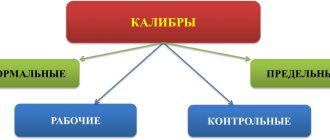
General information and classification of calibers
It should be said right away that gauges do not allow one to completely accurately determine the geometric size of a product; the tool is intended to establish compliance of the part parameters with the dimensions indicated in the drawing. In other words, gauges are used to determine tolerances when manufacturing a part.
Many automakers and builders use this tool to sort parts. Despite the simplicity of the caliber design, it can be used to quickly and easily control a product of even the most complex configuration. True, the tool also has some disadvantages - insufficient versatility and the inability to detect significant deviations in size.
Depending on the type and purpose, calibers are divided into:
- plug gauge;
- ring gauge;
- clamp gauge.
Also, the instrument is usually divided into extreme and normal. Limit gauges have two main parameters, one of which corresponds to the maximum (pass) size of the part, the second – to the minimum (no pass). Normal gauges include the size required for a particular part.
Limit type tools are used more often; normal gauges are usually used as control gauges. In addition, extreme calibers are easy to use without special skills, and the operation of a normal tool requires a high level of professionalism.
The gauges used to carry out control measurements and determine the shape of the part at the initial stage are called working gauges, and those used to control threads are called counter-gauge gauges. There are also receiving gauges used to determine the quality of manufactured products.
Depending on the purpose, there are also several options for the tool. For external threads, threaded ring gauges are used, counter-plug gauges are used for conical rings, for smooth rings, smooth conical plug gauges or conical counter-plug gauges are suitable. Internal threads are measured using smooth or threaded cone plug gauges.
Thread inspection methods | 02/13/2012
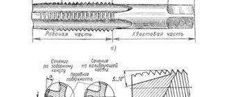
The main thread parameters are the outer, inner and average diameters, pitch and profile angle, as they determine the operational properties of the threaded connection (accuracy, strength, nature of contact, and others). During the manufacturing process of threaded parts, any of these thread elements may have manufacturing errors. In addition, deviations are possible: from the concentricity of the diametrical sections; on specified parameters characterizing the relative position of the thread and other surfaces of the part; discrepancy in the roughness of the threaded surface, etc. All this leads to a violation of interchangeability, deteriorates the quality and make-up of a threaded connection, and reduces its strength. There are two methods for monitoring the accuracy of threads - differentiated (element-by-element) and complex. The differentiated method is used when tolerances for each thread parameter are specified separately. At the same time, the pitch, average diameter, and half of the profile angle are separately controlled. This method is complex and labor-intensive, therefore it is used to control precise threads (gauges, thread-forming tools, special threaded parts), and is also used when setting up a technological process and when investigating the causes of defects. The complex control method is used for threaded parts, the average diameter tolerance of which is the total tolerance. The method is based on simultaneous control of the average diameter, pitch, half of the profile angle, internal and external diameters of the thread by comparing the actual dimensions with the limit ones. This is ensured by the use of extreme calibers. In large-scale and mass production, control of extreme thread gauges is the main thing. This method is also used in single and small-scale production. Thread control with gauges. The kit for checking cylindrical threads includes bushings (ETC) and impassable (NOT) maximum calibers. Working calibers - gauges for checking the correct dimensions of the thread during its manufacture. Control gauges (counter-calibers) - calibers for monitoring or regulating (setting) the sizes of working calibers. To control the dimensions of internal threads, so-called thread plug gauges ( Fig.1)
The screwability of the pass-through plug gauge with the nut means that the average diameter of the nut thread does not exceed the established minimum limit size, and errors in the profile angle and thread pitch of the nut are compensated by a corresponding increase in the average diameter. At the same time, checking with this gauge ensures that the outer diameter of the nut is not less than the outer diameter of the bolt. A no-go plug gauge, as a rule, should not be screwed into the nut. Screwing is allowed:
- for blind threads - no more than two turns;
- for through threads - no more than two turns on each side).
For short threads (up to four turns), screwing in a non-go-through plug gauge is allowed:
- for blind threads - up to two turns on one side;
- for through threads - up to two turns in total on both sides.
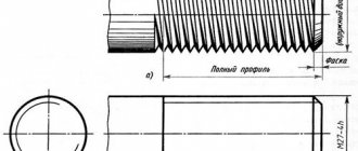
The plug test ensures that the average diameter of the nut is not larger than the specified size limit. To control the dimensions of external threads, so-called thread gauge rings are used ( Fig. 2 ).
The threaded ring through passage must be threaded onto the bolt or similar type of fastener being tested, indicating that the bolt's mean thread diameter is within the specified largest size limit and that errors in the bolt's profile angle and thread pitch are compensated for by a corresponding reduction in the mean diameter. Also, testing with this gauge ensures that the inside diameter of the bolt is not larger than the inside diameter of the nut. A no-go threaded ring should generally not be threaded onto a bolt. Screwing is allowed no more than two turns. Pass-through thread gauges have a full thread profile ( Fig. 3, a ) and a length equal to the make-up length. In fact, they should be a prototype of the mating part. Non-go thread gauges have a shortened profile ( Fig. 3, b ) with a minimum length of the sides of the thread profile and a reduced number of turns. This is done in order to reduce the influence of half-angle and pitch errors and control only the average diameter.
The full thread profile of the gauges is made with a groove of any shape or with a rounded cavity. A shortened thread profile of plug gauges is obtained by reducing the outer diameter of the plugs and cutting grooves at the sockets along the internal diameter; for ring gauges - by increasing the internal diameter and cutting a groove at the socket along the outer diameter. Instead of rigid threaded ring gauges, you can use through and non-go through adjustable ring gauges ( Fig. 4 )
The design of these calibers provides a special adjusting screw, with the help of which, in the conditions of a measuring laboratory using special installation gauges, the caliber is adjusted to a given size and wear is compensated. Roller thread clamps are also used to control external threads (Fig. 5)
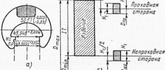
A double-limit roller bracket has two pairs of rollers, in which the thread profile and the distance between the average diameters of the threads of the first pair correspond to the go-through ring, and the same parameters of the second pair correspond to the non-go-through ring. The rollers are installed with eccentricity, which makes it possible to adjust the size. The use of threaded clamps makes it possible to measure parts on centers and significantly reduces auxiliary inspection time because screwing is not required. Threaded staples have a longer lifespan than rings. In Fig. Figure 6 shows the location of the tolerance fields of the average diameter of gauges for monitoring metric threads: a) internal; b) external. Maximum deviations are counted from the corresponding maximum thread dimensions of parts, which in turn are the nominal dimensions of the gauges.
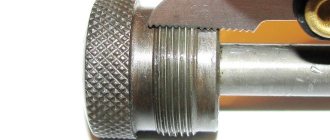
To increase the service life of working thread gauges, a wear tolerance has been established. The tolerance field for wear of passing gauges partially extends beyond the tolerance field of the part thread, and the tolerance field for wear of non-go gauges is located in the tolerance field of the part thread. Marking of thread gauges. When marking, the gauge is marked with the thread size, caliber designations PR or NOT, and the manufacturer's brand. Example of marking: M16X1.5-6g, PR. Control of the outer diameter of the bolt is carried out with extreme smooth staples (Fig. 7), and the internal diameter of the nut is carried out with extreme smooth plugs ( Fig. 8 )
Tapered threads are also controlled by limit plug gauges (Fig. 9) and rings (Fig. 10). Compliance of the thread with the requirements is determined by the axial position of the end of the part relative to the measuring plane of the gauge.
Ring gauges, plug gauges and clamp gauges - their features and purpose
Threaded plug gauges have a one-piece design, complemented by inserts on a conical shank. The tool consists of a threaded part, which is long, and a non-threaded part, which is short. The pass gauge has a full profile, the no pass gauge has from 3 to 5.5 turns in length. In addition, at the end of the non-pass part there is a cylindrical guide. The main task of these instruments is to measure the dimensions of products with the smallest average diameter.
During operation, the plug gauge must be screwed into controlled rings. If the process occurs easily and freely, then the average diameter being checked is not less than the established specific size.
Ring gauges come in two types: they are rigid (non-adjustable) and adjustable. Non-adjustable gauges feature full-width threads, while adjustable gauges have a limited thread profile. In addition, the adjustable rings are equipped with rollers that allow you to adjust the degree of wear. One of the advantages of adjustable gauges is that they can be adjusted repeatedly, thereby increasing the wear resistance and longevity of the tool.
Non-adjustable ring gauges are used to control large product diameters and internal diameters of external threads. The outer diameter cannot be measured this way. Plug gauges can be used to check the degree of ring wear.
The most productive types of gauges are considered to be staples, which are most often used for measuring external threads. Such gauges are easily fixed directly to the product being measured and are quite easy to control and adjust when worn. Unfortunately, such instruments also have their drawbacks: they are easily deformed, leading to significant measurement errors.
TOLERANCES FOR SMOOTH CALIBERS
5.1. The location of the tolerance fields of smooth gauges, as well as the tolerances and values that determine the position of the tolerance fields and the wear limit of the gauges for monitoring the outer diameter of the external thread must correspond to those indicated in Fig. 10 and in Table 7, for monitoring the internal diameter of the internal thread - indicated in Fig. 11 and in table 8.
Damn.10
Table 7
µm
| Td according to GOST 6357 | H2 | HP | Z2 |
| St. 140 to 335 | 16 | 4 | 38 |
| 335 » 850 | 30 | 6 | 54 |
Damn.11
Table 8
µm
| TD1 according to GOST 6357 | H1 | Z1 |
| St. 180 to 375 | 16 | 38 |
| 375 «710 | 26 | 52 |
Features of calculating thread gauges
When designing thread gauges, the following indicators are taken into account:
- step;
- controlled thread tolerance fields;
- make-up length;
- external nominal cross-section.
To calculate metric threads, the nominal internal and average cross-section of the connection is taken into account. For trapezoidal threads, the diameters of the nut (internal and external) and screw (internal) are also taken into account.
The specific shape of the gauge is selected depending on the type of tool.
In modern production, caliber calculations are carried out using special programs.
Basic requirements for calibers
Regardless of the type and purpose, any caliber must meet certain requirements:
- Manufacturing accuracy - the working dimensions of the tool must correspond to the manufacturing tolerances established.
- High rigidity with low weight is necessary to reduce errors in the deformation of gauges (especially large staples) during measurement. Light weight makes it possible to increase the sensitivity of control of medium and large sizes.
- Wear resistance - this indicator is necessary to ensure minimal costs for the manufacture and periodic checking of calibers. For this purpose, the working surface of the tool is made of alloy steel, which is subsequently hardened to increased hardness and chrome-plated.
- The optimal design of the gauges ensures high performance when performing measurements.
- Incorporating heat treatment into the production stage allows for stable tool dimensions to be achieved.
- Anti-corrosion properties are extremely important for the safety of calibers.