GOST 2533-88Group G28
INTERSTATE STANDARD CALIBERS FOR CYLINDRICAL PIPE THREAD Approvals Gauges for straight pipe thread. Tolerances
MKS 17.040.30OKP 39 3154
Date of introduction 1989-01-01
INFORMATION DATA
1. DEVELOPED AND INTRODUCED by the Ministry of Machine Tool and Tool Industry of the USSR
2. APPROVED AND ENTERED INTO EFFECT by Resolution of the USSR State Committee on Standards dated April 27, 1988 N 1167
3. The standard fully complies with ST SEV 354-87.
4. INSTEAD GOST 2533-79
6. REFERENCE REGULATIVE AND TECHNICAL DOCUMENTS
| Designation of the referenced technical document | Item number |
| GOST 6357-81 | Introductory part, section 1, 3.3, 3.7, 4.1, 5.1 |
| GOST 24939-81 | 2.2 |
6. REISSUE
This standard applies to threaded and smooth gauges for monitoring cylindrical pipe threads in accordance with GOST 6357 and establishes the types of gauges, thread profile, length of the working part, tolerances and formulas for determining the sizes of threaded and smooth gauges.
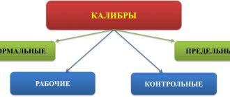
TYPES OF CALIBERS
1. TYPES OF CALIBERS
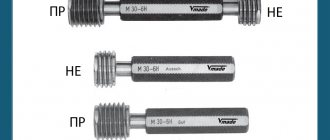
1.1. Gauges for monitoring tapered threads must be manufactured in the following types:
gauges for tapered external threads:
1 - threaded conical ring gauge (Fig. 3);
2 - threaded conical control plug gauge for a threaded conical ring gauge (Fig. 7);
3 - smooth conical ring gauge (Fig. 4);
4 - smooth conical control plug gauge for a smooth conical ring gauge (Fig. 8);
gauges for tapered internal threads:
5 — threaded conical plug gauge (Fig. 5);
6 - smooth conical plug gauge (Fig. 6).
1.2. Gauges for checking conical threads of types 1, 3, 5 and 6 must be manufactured in the following versions:
1 - gauge (plug or ring) with a reference plane corresponding to the nominal position of the main plane of the tapered thread.
2 - gauge (plug or ring) with control planes corresponding to the nominal positions of the main plane of the conical thread and with planes corresponding to the largest and smallest limiting dimensions of the axial displacement of the main plane. Execution 2 is preferred.
1.3. Gauges for monitoring conical external and cylindrical internal threads intended for mutual screwing must be made of the following types: gauges for conical external threads connected to internal cylindrical threads:
7 — threaded ring gauge (Fig. 9);
8 — threaded conical control plug gauge (Fig. 10); gauge for cylindrical internal threads connected to tapered external threads:
9 - threaded conical plug gauge (Fig. 10). Note. Instead of type 9 gauge, it is allowed to use PR and NOT plug gauges in accordance with GOST 24997 to control cylindrical internal threads.
1.4. The caliber designation must consist of the type of caliber and the designation of the thread and the designation of this standard. Examples of symbols for each type of caliber are given in Appendix 2.
2 Normative references
This standard uses references to the following interstate standards:
GOST 2016-86 Threaded gauges. Technical conditions GOST 4608-81 Basic standards of interchangeability. Metric thread. Interference fitsGOST 8724-2002 (ISO 261-98) Basic standards of interchangeability. Metric thread. Diameters and pitchesGOST 9150-2002 (ISO 68-1-98) Basic standards of interchangeability. Metric thread. ProfileGOST 11709-81 Basic standards of interchangeability. Metric thread for parts made of plasticGOST 16093-2004 Basic norms of interchangeability. Metric thread. Tolerances. Landings with clearanceGOST 16967-81 Basic norms of interchangeability. Metric thread for instrument making. Diameters and pitches GOST 24705-2004 Basic norms of interchangeability. Metric thread. Basic dimensionsGOST 24706-81 Basic standards of interchangeability. Metric thread for instrument making. Basic dimensions GOST 24834-81 Basic standards of interchangeability. Metric thread. Transitional fits GOST 24939-81 Calibers for cylindrical threads. Kinds
Note - When using this standard, it is advisable to check the validity of the reference standards using the “National Standards” index compiled as of January 1 of the current year, and according to the corresponding information indexes published in the current year. If the reference standard is replaced (changed), then when using this standard you should be guided by the replaced (changed) standard. If the reference standard is canceled without replacement, then the provision in which a reference is made to it is applied in the part that does not affect this reference.
NOTATION
This standard establishes the following designations:
| — the distance between two adjacent control planes of the ring gauge; |
| — the distance between two adjacent control planes of the plug gauge; |
| — the distance between the control planes of calibers of types 7 and 9; |
| — nominal width of the groove of the threaded conical ring gauge; |
| — nominal width of the groove of the threaded conical plug gauge; |
| — nominal outer diameter of the internal thread in the main plane; |
| — nominal internal diameter of the internal thread in the main plane; |
| - nominal average diameter of the internal thread in the main plane; |
| — the largest average diameter of the ring gauge in the main plane; |
| — the smallest average diameter of the ring gauge in the main plane; |
| — nominal outer diameter of the external thread in the main plane; |
| — nominal internal diameter of the external thread in the main plane; |
| — nominal average diameter of the external thread in the main plane; |
| — the largest average diameter of the plug gauge in the main plane; |
| — the smallest average diameter of the plug gauge in the main plane; |
| — upper deviation of the external thread size; |
| — approval for the production of a smooth conical gauge for internal threads; |
| — approval for the production of a smooth conical gauge for external threads; |
| — approval for the production of a smooth conical control plug gauge for a smooth conical ring gauge; |
| — angle of inclination of the side of the thread of the gauges; |
| — length of the external thread from the end to the main plane; |
| — length of the internal thread from the end to the main plane; |
| - the nominal length of the working surface of the caliber, measured along the axis of the caliber; |
| — basic distance of the caliber-ring; |
| — basic gauge-plug distance; |
| — gauge thread pitch; |
| — nominal radius of curvature of the groove of a threaded conical ring gauge; |
| — nominal radius of curvature of the groove of a threaded conical plug gauge; |
| — tolerance for the manufacture of the average diameter of the threaded control plug gauge; |
| — tolerance of the average diameter of the external thread; |
| — tolerance of the average diameter of the internal thread; |
| — tolerance for the manufacture of the average diameter of the threaded plug gauge; |
| — tolerance for the manufacture of the average diameter of the threaded ring gauge; |
| — tolerance of the angle of inclination of the side of the thread of the gauges; |
| — average permissible wear of threaded plug gauges and ring gauges; |
| — average permissible wear of a smooth conical plug gauge; |
| — average permissible wear of a smooth conical ring gauge; |
| — displacement of the tolerance field of the outer diameter of the threaded conical plug gauge; |
| — displacement of the tolerance field of the internal diameter of the threaded conical plug gauge; |
| — displacement of the middle of the tolerance field of a smooth conical ring gauge; |
| — axial displacement of the main plane of type 9 gauge, corresponding to a tolerance field of 6H of the average diameter of the cylindrical internal thread; |
| — axial displacement of the main plane of the external tapered thread relative to the nominal location; |
| - axial displacement of the main plane of the internal tapered thread relative to the nominal location. |
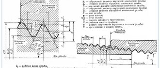
PROFILE AND LENGTH OF THE WORKING PART OF CALIBERS
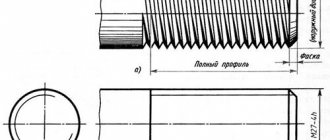
3.1. Plug gauges of types 2, 5, 8 and 9 must have a profile in accordance with Figure 1, ring gauge of type 1 - in accordance with Figure 2.
Damn.1. Plug gauges types 2, 5, 8 and 9
Damn.1
Damn.2. Type 1 ring gauge
Damn.2
The profiles must be made with radii (gauge-ring) and (gauge-plug), which mate tangentially with the straight part of the profile, or with grooves and respectively. The shape of the grooves is arbitrary. Dimensions , , and should not be more than those indicated in Table 1.
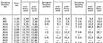
Table 1
mm
| , no more | , no more | , no more | , no more | |
| 1 | — | 0,072 | 0,25 | 0,14 |
| 1,5 | 0,19 | 0,108 | 0,37 | 0,21 |
| 2 | 0,25 | 0,144 | 0,50 | 0,29 |
The type 7 ring gauge must have the full profile of the PR ring gauge in accordance with GOST 24497*. _______________ *Probably an error in the original. You should read GOST 24997.
3.2. The lengths of the working part of the calibers must correspond to those indicated in Figures 3-10 and in Tables 2 and 3.
Damn.3. Threaded cone ring gauges. View 1
Threaded cone ring gauges
View 1
Damn.3
Damn.4. Smooth conical ring gauges. View 3
Smooth conical ring gauges
View 3
Figure 4
Damn.5. Threaded cone plug gauges. View 5
Threaded conical plug gauges
View 5
Figure
Damn.6. Smooth conical plug gauges. View 6
Smooth conical plug gauges
View 6
Figure 6
Damn.7. Threaded conical control plug gauge. View 2
Threaded conical control plug gauge
View 2
Fig.7
Damn.8. Smooth conical control plug gauge. View 4
Smooth conical control plug gauge
View 4
Fig.8
Damn.9. Threaded ring gauge. View 7
Threaded ring gauge
View 7
Figure 9
Damn 10. Threaded cone plug gauges Types 8, 9
Threaded cone plug gauges
Types 8, 9
Drawing 10
table 2
| Type of caliber | ||||||||||||
| Nom. | Prev. off | Nom. | Prev. off | Nom. | Prev. off | Nom. | Prev. off | Nom. | Prev. off | Nom. | Prev. off | |
| 1; 3 | — | — | — | — | — | — | ||||||
| 2; 4 | — | — | — | — | — | — | — | — | — | |||
| 5; 6 | — | — | — | — | — | — | ||||||
| 7 | — | — | — | — | — | — | — | — | ||||
| 8; 9 | — | — | — | — | — | — | — | — | ||||
Note. For caliber type 8, the size is not regulated (see Appendix 1, paragraph 7).
Table 3
mm
| Nominal thread diameter, | * | |
| From 6 to 10 | 1 | 2,40 |
| » 12 » 22 | 1,5 | 3,04 |
| 24 | 1,5 | 3,20 |
| 27 » 45 | 2 | 3,58 |
| 48 » 60 | 2 | 3,78 |
________________ * Corresponds to a tolerance field of 6H, converted to axial displacement.
Appendix A (reference)
Calculation of the dimensions of the elements of the actual thread profile of thread gauges
A.1 Dimensions, mm, and , mm, of the actual thread profile of gauges PR (1), PR (4), PR (7), NE (9), NE (11), NE (14), PR (26) and PR (27) is calculated using the formula
; ,
where is the outer diameter of the thread gauges, mm;
— average diameter of thread gauges, mm.
NOTE Values are calculated in accordance with A.5. calculated using the formulas given in tables 10 and 12.
A.2 Values of dimensions and actual thread profile of gauges KPR-PR (2), U-PR (8), KNE-PR (12), KNE-NE (13), KPR-PR (28), KPR-NE (29 ), K-I (30), U-SR (31), U-SR (32) and U-SR (33) - according to Table 1.
A.3 Dimensions, mm, and , mm, of the actual thread profile of gauges KPR-NE (3), U-PR (5), K-I (6), U-NE (10), U-NE (15), KI-NE (16), PR (21), NE (22), PR (34), SR (35), SR (36) and SR (37) are calculated by the formula
; ,
where is the average diameter of thread gauges, mm;
— internal diameter of thread gauges, mm.
Note - calculated using the formulas given in tables 10-13; calculated in accordance with A.6.
A.4 If the values of , , and are less than or equal to zero, then the gauge can be manufactured with the smallest achievable groove.
Note - Dimensions , , and are initial for the design of a thread-forming tool and are not subject to mandatory control.
A.5 To calculate the outer diameter of the gauge thread (Figures 2 and 4), the value should be subtracted from the values of the outer diameter along the radii calculated using the formulas in Tables 10 and 12.
A.6 To calculate the internal diameter of the gauge thread (Figures 1 and 3), the value should be added to the values of the internal diameter along the radii calculated using the formulas in tables 10-13.
TOLERANCES OF THREAD GAUGES
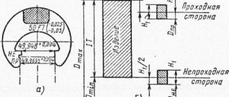
4.1. The location of the tolerance fields for the average thread diameter of the gauges for controlling external threads must correspond to those indicated in Figure 11, for controlling internal threads - in Figure 12.
Damn 11. Location of tolerance fields for the average thread diameter of gauges for checking external threads
Damn.11
Damn.12. Location of tolerance fields for the average thread diameter of gauges for checking internal threads
Damn.12
Note. The numbers next to the tolerance fields indicate the types of calibers.
4.2. Tolerances and values that determine the position of tolerance fields and wear limits must correspond to those indicated in Table 4.
Table 4
Dimensions in microns
| ; | , mm | |||||||
| for ring gauge | for plug gauge | |||||||
| St. 80 to 125 | 1 | 14 | 10 | 8 | 60 | 50 | 16 | — |
| 1 | — | 12 | — | 60 | — | — | 18 | |
| St. 125 to 200 | 1,5 | 18 | 12 | 10 | 80 | 65 | 21 | 18 |
| 2 | 18 | 12 | 10 | 100 | 85 | 21 | — | |
| St. 200 to 315 | 2 | — | 14 | — | 100 | — | — | 21 |
Note. and is determined by recalculating the axial displacement tolerances of the main plane of the thread (external and internal) 2 and 2.
4.3. The tolerance of the angle of inclination of the side of the thread of the gauges must correspond to:
| 30′ - for a step | =1 mm; |
| 24′ » » | =1.5 mm; |
| 20′ » » | =2.0 mm. |
Note. The position of the tolerance field is symmetrical relative to the nominal angle of inclination of the thread flank ().
4.4. The thread pitch tolerance of the gauges must correspond to:
| 5 microns - for working calibers; |
| 3 µm "control". |
Notes: 1. Pitch tolerance values refer to the distances between any threads of the gauge.
2. The actual deviation can have a minus or plus sign.
4.5. The cone deviation, including the deviation of the cone angle, the deviation from the straightness of the generatrix (line of the average diameter) and the deviation from roundness in any section must be within the tolerance zone of the average diameter of the gauge thread. The tolerance zone for the average diameter of the gauge thread is indicated in Fig. 13.
Damn 13. Tolerance zone of average diameter of gauge thread
Damn.13
4.6. The maximum deviations for the coincidence of the control plane of type 1 gauge with the control plane of type 2 control gauge and the plane of type 7 caliber with the control plane of type 8 control gauge should not exceed those indicated in Table 5.
Table 5
mm
| Maximum caliber deviations | ||
| new | worn out | |
| 1 | ±0,048 | +0,192 |
| 1,5; 2 | ±0,064 | +0,256 |
(Changed edition, Amendment No. 2).
*Size for reference.
Official publication ★
Reproduction is prohibited
| Designation traffic jams | using - 1 BRIDGE 1 | d | R | L | D' | Weight, kg, no more | Child 1 Insert PR GOST 17756 O piece) | Det. 2 Insert NOT GOST 17757 (1 piece) | Det. 3 handle GOST N748 (1 pc.) |
| Part designation | |||||||||
| 8221-3013 | 2,0 | 0,40 | 62,0 | 6 | 0,0126 | 8221-0013/1 | 8221-1013/1 | 8054-001! | |
| #221-3015 | 2,2 | 0,45 | 62,0 | 8221-0015/1 | 8221-1015/1 | ||||
| 8221-3017 | — | 2,5 | 0,45 | 62,0 | 8221-0017/1 | 8221-1017/1 | |||
| 8221-3019 | 3,0 | 0,50 | 62,0 | 0,0130 | 8221-0019/1 | 8221-1019/1 | |||
| 8221-3021 | 3,5 | 0,60 | 63,0 | 8221-0021/1 | 8221-1021/1 | ||||
| 8221-3023 | 4,0 | 0,70 | 64,5 | 0,0136 | 8221-0023/1 | 8221-1023/1 | |||
| 8221-3024 | 0,50 | 63,5 | 8221-0024/1 | 8221-1024/1 | |||||
| 8221-3025 | 4,5 | 0,75 | 65,0 | 0,0137 | 8221-0025/1 | 8*221-1025/1 | |||
| 8221-3026 | 0,50 | 63,5 | 8221-0026/1 | 8221-1026/1 | |||||
| 8221-3027 | 5,0 | 0,80 | 65,0 | 0,0139 | 8221-0027/1 | 8221-1027/1 | |||
| 8221-3028 | 0,50 | 63,5 | 8221-0028/1 | 8221-1028/1 | |||||
| 8221-3029 | — | 5,5 | 0,50 | 70,5 | 8 | 0,0284 | 8221-0029/1 | 822М029/1 | 8054-0012 |
| 8221-3030 | 6,0 | 1,00 | 75,5 | 0,0295 | 8221-0030/1 | 8221-1030/1 | |||
| 8221-3031 | 0,75 | 75,0 | 8221-0031/1 | 8221-1031/1 | |||||
| 8221-3032 | 0,50 | 70,5 | 8221-0032/1 | 8221-1032/1 | |||||
| 8221-3033 | — | 7,0 | 1,00 | 75,5 | 0,0305 | 8221-0033/1 | 8221-1033/1 | ||
| 822,1-3034 | 0,75 | 75,0 | 8221-0034/1 | 8221-1034/1 | |||||
| 8221-3035 | 0,50 | 70,5 | 0,0300 | 8221-0035/1 | 8221-1035/1 | ||||
| 8221-3036 | 8,0 | 1,25 | 80,0 | 0,0340 | 8221-0036/1 | 8221-1036/1 | |||
| 8221-3037 | 1,00 | 78,5 | 8221-0037/1 | 8221-1037/1 | |||||
| 8221-3038 | 0,75 | 75,0 | 0,0330 | 8221-0038/1 | 8221-1038/1 | ||||
| 8221-3039 | — | 0,50 | 73,5 | 8221-0039/1 | 8221-1039/1 | ||||
| 8221-3040 | 9,0 | 1,25 | 80,0 | 0,0360 | 8221-0040/1 | 8221-1040/1 | |||
| 8221-3041 | 1,00 | 78,5 | 8221-0041/1 | 8221-1041/1 | |||||
| 8221-3042 | 0,75 | 75,0 | 0,0350 | 8221-0042/1 | 8221-1042/1 | ||||
| 8221-3048 | 0,50 | 73,5 | 8221-0043/1 | 8221-1043/1 | |||||
| 8221-3044 | 10,0 | 1,50 | 83.5 | 0,041 | 8221-0044/1 | 8221-1044/1 |
| Designation traffic jams | TO & A 2 b S o | d | R | L | D | Weight, kg, no more | Det. /* Insert PR GOST 17756 (1 pc.) | Det. 2. Insert NOT GOST 17757 (1 pc.) | Det. 3. Handle GOST 14748 (1 piece) |
| A O CIS | Part designation | ||||||||
| S221-3045 | 1,25 | 83,0 | 0,041 | 8221-0045/1 | 8221-1045/1 | ||||
| 8221-3046 | 10,0 | 1,00 | 78,5 | 8 | 8221-0046/1 | 8221-1046/1 | 8054-0012 | ||
| 8221-3047 | 0,75 | 75,0 | 0,036 | 8221-0047/1 | 8221-1047/1 | ||||
| 8221-3048 | 0,50 | 73,5 | 8221-0048/1 | 8221-1048/1 | |||||
| 8221-3049 | 1,50 | 93,5 | 0,049 | 8221-0049/1 | 8221-1049/1 | ||||
| 8221-3050 | 11,0 | 1,00 | 88,5 | 8221-0050/1 | 8221-1050/1 | ||||
| 8221-3051 | 0,75 | 85,0 | 0,044 | 8221-0051/1 | 8221-1051/1 | ||||
| 8221-3052 | 0,50 | 83,5 | 8221-0052/1 | 8221-1052/1 | |||||
| 8221-3053 | 1,75 | 98,0 | 8221-0053/1 | 8221-1053/1 | |||||
| 8221-3054 | 1,50 | 96,0 | 0,055 | 8221-0054/1 | 8221-1054/1 | ||||
| 8221-3055 | 12,0 | 1,25 | 93,0 | 8221-0055/1 | 8221-1055/1 | ||||
| 8221-3056 | 1,00 | 88,5 | 10 | 8221-0056/1 | 8221-1056/1 | 8054-0013 | |||
| 8221-3057 | 0,75 | 88,0 | 0,050 | 8221-0057/1_ | 8221-1057/1 | ||||
| 8221-3058 | 0,50 | 83,5 | 8221-0058/1 | 8221-1058/1 | |||||
| 8221-3059 | 2,00 | 100,5 | 0,068 | 82210059/1 | 8221-1059/1 | ||||
| 8221-3060 | 1,50 | 96,0 | 82210060/1 | 8221-1060/1 | |||||
| 8*221-3061 | 14 | 1,25 | 93,0 | 0,062 | 8221-0061/1 | 8221-1061/1 | |||
| 8221-3062 | 1,00 | 91,5 | 82210062/1 | 3221-1062/1 | |||||
| 8221-3063 | 0,75 | 88,0 | 0,054 | 8221-0063/1 | 8221-1063/1 | ||||
| 8221-3064 | 0,50 | 83,5 | 8221-0064/1 | 8221-1064/1 | |||||
| 8221-3065 | 15 | 1,50 | 108,0 | 0,099 | 8221-0065/1 | 8221-1065/1 | |||
| 8221-3066 | 1,00 | 103,5 | 82210066/1 | 8221-1066/1 | |||||
| 8221-3067 | 2,00 | 112,5 | 0,112 | 8221-0067/1 | 8221-1067/1 | ||||
| 8221-3068 | 16 | 1,50 | 108,0 | 13 | 82210068/1 | 8221-1068/1 | 8054-0014 | ||
| 8221-3069 | 1,00 | 103,5 | 0,107 | 82210069/1 | 8221-1069/1 | ||||
| 8221-3070 | 0,75 | 100,0 | 0,096 | 8221-0070/1 | 3221-1070/1 | ||||
| 8221-3071 | 0,50 | 95,5 | 0,090 | 8-2210071/1 | 8221-1071/1 |
Continuation
| Designation traffic jams | Apply bridge | d | R | L | ABOUT | Weight, kg, no more | Child 1 Insert PR GOST 17756 (1 piece) | Det 2 Insert NOT GOST 17757 (1 piece) | Det 3 Handle GOST 14748 (1 piece) |
| Part designation | |||||||||
| 8221-3072 | 17 | 1,50 | 108,0 | 13 | 0,112 | 8221-0072/1 | 8221-1072/1 | 8054-0014 | |
| 8221-3073 | 1,00 | 103,5 | 0,107 | 8221-0073/1 | 8221-1073/1 | ||||
| 8221-3074 | 18 | 2,50 | 119,5 | 0,141 | 8221-0074/1 | 8221-1074/1 | |||
| 8221-3075 | 2,00 | 114,5 | 8221-0075/1 | 8221-1075/1 | |||||
| 8221-3076 | 1,50 | 108,0 | 0,131 | 3221-0076/1 | 8221-1076/1 | ||||
| 8221-3077 | 1,00 | 103,5 | 0,117 | 8221-0077/1 | 8221-1077/1 | ||||
| 8221-3078 | 0,75 | 100,0 | 0,112 | 8221-0078/1 | 8221-1078/1 | ||||
| 8221-3079 | 0,50 | 98,5 | 8221-0079/1 | 8221-1079/1 | |||||
| 8221-3080 | 20 | 2,50 | 131,5 | 16 | 0,213 | S221-0080/1 | 8221-1080/1 | 8054-0015 | |
| 8221-3081 | 2,00 | 126,5 | 8221-0081/1 | 8221-1081/1 | |||||
| 8221-3082 | 1,50 | 120,0 | 0,187 | 8221-0082/1 | 8221-1082/1 | ||||
| 8221-3083 | 1,00 | 115,5 | 8221 0083/1 | 8221-1083/1 | |||||
| 8221-3084 | 0,75 | 112,0 | 0,170 | 8221-0084/1 | 8221-1084/1 | ||||
| 8221-3085 | 0,50 | 110,5 | 8221-0085/1 | 8221-1085/1 | |||||
| 8221-3086 | 22 | 2,50 | 131,5 | 0,231 | 8221-0086/1 | 8221-1086/1 | |||
| 8221-3087 | 2,00 | 126,5 | 8221-0087/1 | 8221-1087/1 | |||||
| 8221-3088 | 1,50 | 120,0 | 0,212 | 8221-0088/1 | 8221-1088/1 | ||||
| 8221-3089 | 1,00 | 115,5 | 0,196 | 8221-0089/1 | 8221-1089/1 | ||||
| 8221-3090 | 0,75 | 112,0 | 0,185 | 8221-0090/1 | 8221-1090/1 | ||||
| 8221-3091 | 0,50 | 110,5 | 8221-0091/1 | 8221-1091/1 | |||||
| 8221-3092 | 24 | 3,00 | 139,5 | 0,281 | 8221-0092/1 | 8221-1092/1 | |||
| 8221-3093 | 2,00 | 126.5 123.5 | 0,238 | 8221 0093/1 | 8221-1093/1 | ||||
| 8221-3094 | 1,50 | 0,235 0,220 | 8221-0094/1 | 8221-1094/1 | |||||
| 8221-3095 | 1,00 | 118,5 | 8221-0095/1 | 8221-1095/1 | |||||
| 8221-3096 | 0,75 | 114,5 | 8221-0096/1 | 8221 1096/1 | |||||
| 25 | 20 | 0,317 0,310 | |||||||
| 8221-3097 | 2,00 | 138,5 | 8221-0097/1 | 8221-1097/1 | 8054-0016 | ||||
| 8221-3098 | 1,50 | 135,5 | 8221 0098/1 | 8221-1098/1 |
| Designation traffic jams | t SI IN y l * o | d | R | L | D | Weight, kg, not more | Child 1 Insert PR GOST 17756 (1 piece) | Det 2 Insert YA GOST J 7757 (1 piece) | Det. 3, Handle GOST 14748 (1 piece) |
| tii About SG | Part designation | ||||||||
| 8221-3099 | 25 | 1,00 | 130,5 | 0,300 | 1 8221-0099/1 | 8221-1099/1 | |||
| 8221-3100 | 26 | 1,50 | 135,5 | 0,315 | | 8221-0100/1 | 8221-1100/1 | |||
| 8221-3101 | 3,ii | 151,5 | 0,400 | ‘8221-0101/1 | 8221-1101/1 | ||||
| 8221-3102 | 2,00 | 138,5 | 0,347 | 8221-01’02/1 | 8221-1102/1 | ||||
| 8221-3103 | 27 | 1,50 | 135,5 | 0,335 | 8221-0103/1 | 8221-1103/1 | |||
| 8221-3104 | 1,00 | 130,5 | 0,305 | 8221-0104/1 | 8221-1104/1 | ||||
| 8221-3105 | 0,75 | 126,5 | 8221-0105/1 | 8221-1105/1 | |||||
| 8221-3106 | 2,00 | 138,5 | 0,355 | 8221-0106/1 | 8221-1106/1 | ||||
| 8221-3107 | 28 | 1,50 | 135,5 | 20 | 8221-0107/1 | 8221-1107/1 | 8054-0016 | ||
| 8221-3108 | 1,00 | 130,5 | 0,315 | 8221-0108/1 | 8221-1108/1 | ||||
| 8221-3109 | 3,50 | 158,0 | 0,480 | 8221-0109/1 | 8221-1109/1 | ||||
| 8221-3110 | 3,00 | 154,5 | 8221-0110/1 | 8221-1110/1 | |||||
| 8221-3111 | 30 | 2,00 | 140,5 | 0,395 | 8221-0111/1 | 8221-1111/1 | |||
| 8221-3112 | 1,50 | 137,5 | 8221-0112/1 | 8221-1112/1 | |||||
| 8221-3113 | 1,00 | 132,5 | 0,355 | 8221-0113/1 | 8221-1113/1 | ||||
| 8221-3114 | 0,75 | 129,5 | 8221-0114/1 | 8221-0114/1 | |||||
| 8221-3115 | 32 | 2,00 | 142.5 | 0,480 | 8221-0115/1 | 8221-1115/1 | |||
| 8221-3116 | 1,50 | 139,5 | 8221-0116/1 | 8221-1116/1 | |||||
| 8221-3117 | 3,50 | 160,0 | 0,67 | 8221-0117/1 | 8221-1117/1 | ||||
| 8221-3118 | 3,00 | 156,5 | 8221-0118/1 | 8221-1118/1 | |||||
| 8221-3119 | 33 | 2,00 | 142,5 | 0,56 | 8221-0119/1 | 8221-1119/1 | |||
| 8221-3120 | 1,50 | 139,5 | 8221-0120/1 | 8221-1120/1 | |||||
| 8221-3121 | 1,00 | 134,5 ; | 24 | 0,50 | 8221-0121/1 ■ | 8221-1121/1 | 8054-0017 | ||
| 8221-3122 | 0,75 | 131,5 | 8221-0122/1 : | 8221-1122/1 | |||||
| 8221-3123 | 35 | 1,50 | 139,5 | 0,57 : | 8221-0123/1 , | 8221-1123/1 | |||
| 8221-3124 | 36 ‘ | 4,00 | 167,0 | 0,78 ; | 8221-0124/1 , | S221-1124/1 | |||
| 8221-3125 | 3,00 | 156,5 | O O | 8221-0125/1 1 | 8221-1125/1 |
Continuation
| Designation traffic jams | <and TO X a>l 2 fr- I'm about | d | R | L | D | Weight, kg, no more | Yaet 1 Insert PR GOST 17756 (1 piece) | Child 2 Insert NOT GOST) 7757 * 1 piece) | Det. 3. Handle GOST 14748 (1 pc.) |
| o>o as | Part designation | ||||||||
| 8221-3126 | 2,00 | 144,0 | 0,63 | 8221-0126/1 | 8221-1126/1 | ||||
| 3221-3127 | 36 | 1,50 | 139,5 | 0,57 | 8221-0127/1 | 8221-1127/1 | |||
| 8221-3128 | 1,00 | 135,5 | 8221-0128/1 | 8221-1128/1 | |||||
| 8221-3129 | 38 | 1,50 | 140,0 | 0,60 | S221-0129/1 | 8221-1129/1 | |||
| 8221-8130 | 4,00 | 167,0 | 0,88 | 8221-0130/1 | 8221 -1130/1 | ||||
| 8221-3131 | 3,00 | 156,5 | 24 | 0,78 | 8221-0131/1 | 8221-1131/1 | 8054-0017 | ||
| 8221-3132 | 39 | 2,00 | 144,0 | 8221-0132/1 | 8221-1132/1 | ||||
| 8221-3133 | 1,50 | 140,0 | 0,67 | 3221-0133/1 | 8221-1133/1 | ||||
| 8221-3134 | 1,00 | 136,5 | 8221-0134/1 | 8221 1134/1 | |||||
| 8221-3135 | 3,00 | 156,5 | 0,81 | 8221-0135/1 | 8221-1135/1 | ||||
| 8221-3136 | 40 | 2,00 | 144,0 , | 0,68 | 8221-0136/1 | 8221-1136/1 | |||
| 8221-3137 | 1,50 | 140,0 | 8221-0137/1 | 8221-1137/1 | |||||
| 8221-3138 | 4,5 | 188,0 | 1,19 | 8221-0138/1 | 822L-1138/1 | ||||
| 8221-3139 | 4,0 | 183,0 | 8221-0139/1 | 8221-1339/1 | |||||
| 8221-3140 | 42 | 3,0 | 168,5 | 1,00 | В'221-0140/1 | 8221-1140/1 | |||
| 8221-3141 | 2,0 | 158,0 | 8221-0141/1 | 8221-1141/1 | |||||
| 8221-3142 | 1,5 | 154,0 | 0,87 | 8221-4)140/1 | 8221-114(2/1 | ||||
| 8221-3143 | 1,0 | 150,5 | 8221-0143/1 | 8221-1143/1 | |||||
| 8221-3144 | 4,5 | 188,0 | 28 | 1,30 | 8221-0144/1 | 8221-1144/1 | 8054-0018 | ||
| 8221-3145 | 4,0 | 183,0 | 8221-0145/1 | 8221-1145/1 | |||||
| 8221-3146 | 45 | 3,0 | 168,5 | 1,07 | 8221-0146/1 | 8221-1146/1 | |||
| 8221-3147 | 2,0 | 158,0 | 0,93 | 8221-0147/1 | 8221-1147/1 | ||||
| 8221-3148 | 1,5 | 154,0 | 8221-0148/1 | 8221-1148/1 | |||||
| 8221-3149 | 1,0 | 150,5 | 0,89 | 8221-0149/1 | 8221-1149/1 | ||||
| 8221-3150 | 5,0 | 195,5 | 1,55 | 8221-0150/1 | 8221-1150/1 | ||||
| 8221-3151 | 48 | 4,0 | 184,0 | 1,44 , | 3221-0151/1 . | 8221-1151/1 | |||
| 8221-3152 | 3,0 | 170,0 | 1,18 | 8221-0152/1 ; | 8221-1152/1 |
| Designation piobok | To X 2 liters | d | R | 1 | ABOUT | Weight, kg, no more | Child 1-Insert PR GOST 17756 (1 pc.) | Det. 2. Insert NOT GOST 17757 (1 piece) . | Det. 3. Handle GOST 14748 (1 piece) |
| 0-0 Cr s | Part designation | ||||||||
| 8221-3153 | 2,0 | 158,0 | 8221-0153/1 | 8221-1153/1 | |||||
| 8221-3154 | 48 | 1,5 | 154,0 | 1,00 | 8221 L) 154/1 | 822 Ml 54/1 | |||
| 8221-3155 | 1,0 | 150,5 | 28 | 8221-0155/1 | 8221-1155/1 | 8054-0018 | |||
| 8221-3156 | 3,0 | 170,0 | 1,23 | 8221-0156/1 | 8221-1156/1 | ||||
| 8221-3157 | 50 | 2,0 | 158,0 | 1,06 | 8221-0157/1 | 8221-1157/1 | |||
| 8221-3158 | 1,5 | 154,0 | 8221-0158/1 , | 8221-1158/1 |
P
14748.
Note. Use of handles is allowed
version 2 according to GOST
An example of a symbol for a double-sided plug for monitoring a threaded hole with a right-hand thread M10x 1.25 with a tolerance range of 6H:
CALCULATION OF THREAD GAUGES
The dimensions of the outer, middle and inner diameters of the thread of the gauges must be determined according to the formulas indicated in Table 6.
Table 6
| Type of caliber | Diameters in the main plane | ||||||
| Outer | Average | Interior | |||||
| Nom. | Prev. off | Nom. | Prev. off | Wear limit | Nom. | Prev. off | |
| 1; 7 | , no less | — | |||||
| 2 | — | , no more | — | ||||
| 5; 9 | , no more | — | |||||
| 8 | — | , no more | — | ||||
Note. The dimensions and maximum deviations of the average diameter of ring gauges of types 1 and 7 are indicated to coordinate the tolerance fields of control gauges and control them with universal measuring instruments.
7 Formulas for calculating the maximum sizes of calibers
7.1 The dimensions of the thread diameters of gauges for monitoring external threads according to GOST 4608 (without sorting into groups), GOST 11709, GOST 16093 and GOST 24834 should be determined according to the formulas given in Table 10, for internal threads - in Table 11.
Table 10
| Caliber designation | Name and purpose of caliber | Figure number | Outside diameter | Average diameter | Inner diameter | |||||
| Nom. | Prev. off | Nom. | Prev. off | Nom. | Prev. off | |||||
| PR (1) | Threaded straight-through non-adjustable ring gauge | 2 | Along the groove or radius, not less | |||||||
| KPR-PR (2) | Threaded control go-through plug gauge for the new threaded go-through non-adjustable ring gauge | 1 | See note 6 | Along a groove or radius, no more | ||||||
| KPR-NOT (3) | Threaded control no-go plug gauge for the new threaded go-through non-adjustable ring gauge | 3 | Along a groove or radius, no more | |||||||
| PR (4) | Threaded straight-through adjustable ring gauge | 2 | Along the groove or radius, not less | Not regulated, but determined by the calibers U-PR (5) and KPR-NE (3) | ||||||
| U-PR (5) | Threaded installation plug gauge for threaded straight-through adjustable ring gauge | 1 | Along a groove or radius, no more | |||||||
| K-I (6) | Threaded control plug gauge for monitoring the wear of threaded straight-through non-adjustable and adjustable ring gauges | 3 | See note 4 | Along a groove or radius, no more | ||||||
| PR (7) | Threaded pass-through clamp gauge | 2 | Dimensions and maximum deviations are not regulated, but are determined by the U-PR (8) and KPR-NE (3) calibers. Radial runout of rollers is no more than 5 microns. | |||||||
| U-PR (8) | Threaded installation plug gauge for threaded pass-through clamp gauge | 1 | Along a groove or radius, no more | |||||||
| NOT (9) | Threaded no-go clamp gauge | 4 | Dimensions and maximum deviations are not regulated, but are determined by the U-NE (10) and KNE-NE (13) gauges. Radial runout of rollers is no more than 5 microns. Execution of the video in accordance with 4.8. | |||||||
| U-NE (10) | Threaded installation plug gauge for threaded no-go clamp gauge | 1 | Along a groove or radius, no more | |||||||
| NOT (11) | Threaded no-go non-adjustable ring gauge | 4 | Along the groove or radius, not less | |||||||
| KNE-PR (12) | Threaded control go-through plug gauge for a new threaded non-go through non-adjustable ring gauge | 1 | Along a groove or radius, no more | |||||||
| ___________________ * Original error. Should read "". — Note from the database manufacturer. | ||||||||||
| KNE-NE (13) | Threaded control no-go gage-plug for a new threaded no-go non-adjustable ring gage | 1 | Along a groove or radius, no more | |||||||
| NOT (14) | Threaded no-go adjustable ring gauge | 4 | Along the groove or radius, not less | Not regulated, but determined by the U-NE (15) and KNE-NE (13) calibers | ||||||
| U-NE (15) | Threaded installation plug gauge for threaded no-go adjustable ring gauge | 1 | Along a groove or radius, no more | |||||||
| KI-NE (16) | Threaded control plug gauge for monitoring the wear of threaded no-go non-adjustable and adjustable ring gauges | 1 | See note 4 | Along a groove or radius, no more | ||||||
| Notes 1 Numerical values should be taken taking into account their signs. 2 Formulas for calculating sizes and maximum deviations of the average diameter of ring gauges PR (1) and HE (11) are given for coordinating the tolerance fields of control gauges and monitoring ring gauges with measuring instruments. 3 When calculating the executive dimensions of gauges, the smallest limit size for ring gauges and the largest maximum size for control plug gauges should be determined. 4 The values of both plug gauges K-I (6) and KI-NE (16) should be taken according to table 5 for ring gauges. 5 When calculating the dimensions of ring gauges PR (1) with a nominal thread diameter over 160 mm, by agreement with the customer, it is allowed to increase the tolerance of the internal diameter ± to ±. 6 If for ring gauges NOT (11) and NOT (14), with a small thread pitch and a large tolerance of the average diameter, it turns out to be impossible to make the outer diameter larger than the largest outer diameter of the controlled thread, then it should be reduced so that there is dullness no larger than 0.03 mm. The same applies to the outer diameter of the control plug gauges. 7 Due to possible cases of incorrect assessment of the suitability of threads with small pitches, ring gauges HE (11) and HE (14) are recommended to be used to control threads with average diameter tolerances of the 4th and 6th degrees of accuracy - starting from a pitch of 0.4 mm, 7th degree of accuracy - starting from a step of 0.5 mm, 8th degree of accuracy - starting from a step of 1.0 mm and degrees of accuracy 9th and 10th - starting from a step of 1.25 mm. It is recommended to check threads with smaller pitches using measuring instruments. 8 If the internal diameter of the ring gauges NOT (11) and NOT (14) is less than the internal diameter of the ring gauges PR (1) and PR (4), then for the smallest internal diameter of the ring gauges NOT (11) and NOT (14) the corresponding smallest internal diameter of the ring gauges PR (1) and PR (4) is accepted and with a positive maximum deviation equal to the tolerance of the internal diameter of the ring gauges NOT (11) and NOT (14). 9 Instead should be used, and instead -, if and were calculated according to the formulas specified in Appendix A for the actual thread profile. 10 When inspecting threads of accuracy levels 7–10 on parts made of plastics produced by injection molding or pressing, by agreement with the customer, it is allowed to use only threaded go-through and smooth non-go-through gauges. | ||||||||||
Table 11
| Caliber designation | Name and purpose of caliber | Figure number | Outside diameter | Average diameter | Inner diameter | ||||
| Nom. | Prev. off | Nom. | Prev. off | Wear limit | Nom. | Prev. off | |||
| PR (21) | Threaded feedthrough gauge - plug | 1 | Along a groove or radius, no more | ||||||
| NOT (22) | Threaded no-go gauge - plug | 3 | Along a groove or radius, no more | ||||||
| Notes 1 When calculating the executive dimensions of calibers, the largest maximum size should be determined. 2 If for plug gauges HE (22), with a small thread pitch and a large tolerance of the average diameter, it turns out to be impossible to make the internal diameter smaller than the smallest internal diameter of the controlled thread, then it should be increased so that the thread cavities have a bluntness of no more than 0 .03 mm. 3 Due to possible cases of incorrect assessment of the suitability of threads with small pitches, the plug gauge HE (22) is recommended to be used to control threads with average diameter tolerances of accuracy degrees 4, 5 and 6 - starting from a pitch of 0.4 mm, degree 7th accuracy - starting with a step of 0.5 mm and degrees of accuracy 8th and 9th - starting with a step of 0.8 mm. It is recommended to check threads with smaller pitches using measuring instruments. 4 Instead should be used, and instead -, if and were calculated using the formulas specified in Appendix A for the actual thread profile of the gauges. | |||||||||
7.2 The dimensions of the thread diameters of gauges for checking external threads in accordance with GOST 4608, sorted into groups, must be determined according to the formulas given in Table 12, for internal threads - in Table 13.
Table 12
| Caliber designation | Name and purpose of caliber | Figure number | Outside diameter | Average diameter | Inner diameter | |||
| Nom. | Prev. off | Nom. | Prev. off | Nom. | Prev. off | |||
| PR (26) | Threaded pass-through clamp gauge (with shortened thread profile) | 4 | Dimensions and maximum deviations are not regulated, but are determined by the KPR-PR (28) and KPR-NE (29) calibers. Radial runout of rollers is no more than 5 microns. Execution of the video in accordance with 4.8. | |||||
| PR (27) | Threaded straight-through non-adjustable ring gauge (with shortened thread profile) | 4 | Along the groove and radius, not less | |||||
| KPR-PR (28) | Threaded control pass-through gauge-plug for the new threaded pass-through non-adjustable gauge-ring and threaded installation gauge-plug for the threaded pass-through gauge-bracket | 1 | Along a groove or radius, no more | |||||
| KPR-NOT (29) | Threaded control no-go plug gauge (with full thread profile) for the new threaded go-through non-adjustable ring gauge | 1 | Along a groove or radius, no more | |||||
| K-I (30) | Threaded control plug gauge (with full thread profile) for monitoring the wear of a threaded straight-through non-adjustable ring gauge | 1 | Along a groove or radius, no more | |||||
| U-SR (31) | Threaded installation plug gauge for a measuring device used for sorting threads into groups I or II when sorting into two groups | 1 | Along a groove or radius, no more | |||||
| U-SR(32) | Threaded installation plug gauge for a measuring device used for sorting threads into l and ll groups when sorting into three groups | 1 | Along a groove or radius, no more | |||||
| U-SR(33) | Threaded installation plug gauge for a measuring device used for sorting threads into groups II and III when sorting into three groups | 1 | Along a groove or radius, no more | |||||
| Notes 1 When calculating the executive dimensions of gauges, the smallest limit size for ring gauges and the largest maximum size for control plug gauges should be determined. 2 Instead should be used , and instead - , if and were calculated using the formulas specified in Appendix A for the actual thread profile of the gauges. | ||||||||
Table 13
| Caliber designation | Name and purpose of caliber | Figure number | Outside diameter | Average diameter | Inner diameter | ||||
| Nom. | Prev. off | Nom. | Prev. off | Wear limit | Nom. | Prev. off | |||
| PR (34) | Threaded feedthrough plug gauge (with shortened thread profile) | 3 | Along a groove or radius, no more | ||||||
| SR (35) | Thread sorting gauge-plug for sorting threads on I and | 3 | It is allowed to increase the smallest limit size of the average diameter of the gauge thread by a value of up to to ensure a reserve for wear | Along a groove or radius, no more | |||||
| SR(36) | Thread sorting gauge-plug for sorting threads on I and | 3 | Along a groove or radius, no more | ||||||
| SR(37) | Threaded sorting plug gauge for sorting threads into groups II and III when sorting into three groups | 3 | Along a groove or radius, no more | ||||||
| Notes 1 When calculating the executive dimensions of gauges, the largest maximum size should be determined. Should be used instead if it was calculated using the formulas specified in Appendix A for the actual thread profile of the gauges. | |||||||||
7.3 The dimensions of the diameters of smooth gauges for monitoring the outer diameter of the external thread should be determined according to the formulas given in Table 14, for monitoring the internal diameter of the internal thread - in Table 15.
Table 14
| Caliber designation | Name and purpose of caliber | Caliber diameter, mm | |
| Nom. | Prev. off | ||
| PR (17) | Smooth pass-through ring gauge or smooth pass-through clamp gauge | ||
| NOT (18) | Smooth no-go clamp gauge or smooth no-go ring gauge | ||
| K-PR (19) | Smooth check-through plug gauge for the new smooth pass-through clamp gauge | ||
| K-NOT (20) | Smooth control pass-through plug gauge for the new smooth non-go-through clamp gauge | ||
| K-I (25) | Smooth check gauge-plug for monitoring the wear of the smooth pass-through gauge-clip | ||
| Notes 1 Values should be taken taking into account their signs. 2 When calculating the executive dimensions of gauges, the smallest limit size for ring gauges (staples) and the largest maximum size for plug gauges should be determined. | |||
Table 15
| Caliber designation | Name and purpose of caliber | Caliber diameter, mm | |
| Nom. | Prev. off | ||
| PR (23) | Smooth pass-through plug gauge | ||
| NOT (24) | Smooth no-go plug gauge | ||
| Note - When calculating the executive dimensions of gauges, the smallest limit size for ring gauges (staples) and the largest maximum size for plug gauges should be determined. | |||
TOLERANCES FOR SMOOTH CALIBERS
6.1. The location of the tolerance fields of the gauges for monitoring the outer diameter of the external thread must correspond to that indicated in Figure 14, for monitoring the internal diameter of the internal thread - in Figure 15.
Damn.14. Location of tolerance fields of gauges for controlling the outer diameter of an external thread
Damn.14
Damn.15. Location of tolerance fields of gauges for monitoring the internal diameter of the internal thread
Damn.15
6.2. Tolerances and values that determine the position of tolerance fields and wear limits must correspond to those indicated in Table 7.
Table 7
µm
| 1_ 1,5 2 | 5 | 5 | 1,5 | 32 48 64 | 22 | 20 |
6.3. The cone deviation, including the cone angle deviation, the generatrix deviation from straightness and the deviation from roundness in any section, must be within the tolerance zone of the corresponding diameter in the main plane.
6.4. The maximum deviations in the coincidence of the control plane of type 3 caliber with the control plane of type 4 control caliber should not exceed ±0.056 mm for a new caliber and +0.296 mm for an extremely worn one.
CALCULATION OF SMOOTH CONE GAUGES
The dimensions in the main plane of smooth conical gauges should be determined according to the formulas indicated in Table 8.
Table 8
| Type of caliber | Nom. | Limit deviations | Wear limit |
| 3 | |||
| 4 | — | ||
| 6 |
Note. The size and maximum deviations of the internal diameter of the type 3 ring gauge are indicated to coordinate the tolerance fields of the control gauge and control them by universal means.
APPENDIX 1 (mandatory). RULES FOR APPLICATION OF CALIBERS
APPENDIX 1 Mandatory
1. Threaded cone gauges of types 1 and 5 to control the displacement of the main plane of the conical thread. When screwing together a threaded cone gauge in version 1 with a conical thread, its control plane must coincide with the end of the product. The permissible deviation should not exceed those specified in Table 2 of GOST 25229. When screwing a threaded cone gauge in version 2 with a product, the end of the product must be between the control planes of the gauge or coincide with one of them. When using calibers as receiving gauges (at the consumer of products), discrepancies between the end of the products and the control plane of calibers in version 1 are allowed by ±1.5. For calibers in version 2, the end of the product is allowed to extend beyond the ledges of the caliber by 0.5.
2. Smooth cone gauges of types 3 and 6 to control the deviations of the cut of the tips of the conical thread. Smooth cone gauges are used only in combination with threaded cone gauges. In this case, the position of the same control planes of the threaded conical and smooth conical gauges in relation to the end of the product must coincide. The permissible deviation from the coincidence of the same control planes of threaded and smooth conical gauges should not exceed ±1 mm.
3. Threaded conical control plug gauge of type 2 for monitoring a threaded conical ring gauge of type 1. When screwing the control gauge with the ring gauge, their control planes must coincide. Limit deviations from coincidence should not exceed the values specified in Table 5 of this standard.
4. Smooth conical control plug gauge of type 4 to control a smooth conical ring gauge of type 3. The control gauge must fit into the ring gauge, and their control planes must coincide. The maximum deviations from coincidence are specified in clause 6.4 of this standard.
5. Thread ring gauge type 7 to control the displacement of the main plane of a conical external thread intended for screwing with a cylindrical internal thread. When screwing a type 7 ring gauge with a product, the end of the product must be between the control planes of the gauge or coincide with one of them.
6. Threaded conical plug gauge type 9 for monitoring the average diameter of a cylindrical thread intended for screwing with a tapered external thread. When screwing a type 9 plug gauge with a product, the end of the product must be between the control planes of the gauge or coincide with one of them.
7. Threaded conical control plug gauge of type 8 for monitoring the threaded ring gauge of type 7. The plane of the ring gauge of type 7 must coincide with the control plane (coinciding with the main plane) of the control gauge of type 8.
8. Limit deviations from coincidence are indicated in Table 5 of this standard.
GAUGES FOR CYLINDRICAL THREADS
Kinds
Gauges for parallel threads.
Types GOST
24939-81
MKS 17.040.30 OKI 39 3100
Date of introduction 01/01/82
1. This standard applies to threaded and smooth gauges for monitoring cylindrical threads with tolerances in accordance with GOST 4608 GOST 6357 GOST 9562 GOST 13535 GOST 16093 GOST 24739 GOST 24834 GOST 25096 and ST SEV 3962 and establishes the names of types of gauges and their designations.
This standard does not apply to gauges of types 3.6, 11 and 22 for thread control in accordance with GOST 24739 in terms of the rules for their use.
The standard fully complies with ST SEV 1921.