01.07.2020
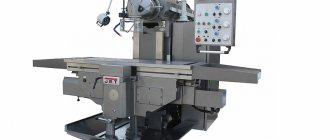
Today, one of the most popular equipment options is under the spotlight. Let's look at what a dividing head for a milling machine is, the main features of the unit, what types there are, where it is used, how to operate it correctly, and so on. We will try to provide as many facts as possible so that you understand whether to install it to perform operations that are relevant to you or not.
Note that it can also be an important component of slotting, boring, drilling, planing equipment models. With its help, teeth, splines and grooves are cut, markings are made, the table is positioned, polyhedra and interdental cavities are machined, and rotation is coordinated with axial feed.
Now the definition: a simple or universal dividing head (UDG) is an equipment, that is, an additional machine tool, horizontally oriented, that serves to securely secure the workpiece, as well as to rotate it to the desired angle and/or divide it into the required number of parts equal to or not.
It expands the technological capabilities of the equipment and opens up new options and positions for processing parts. This determines the breadth of its modern use in mass and individual production, along with ease of installation, ease of commissioning, and reliable operation even under significant workload.
Information about the manufacturer of dividing heads UDG-200 (UDG-D-200)
The developer and manufacturer of the UDG-200 (UDG-D-200) dividing heads until 1990 was the Leningrad Optical-Mechanical Association LOMO .
Currently, the production and sale of universal dividing heads UDG-160 (UDG-D-160), UDG-200 (UDG-D-200), UDG-250 (UDG-D-250), UDG-320 (UDG-D- 320) is carried out by Production , which was founded in 1990 on the basis of OJSC LOMO.
Products manufactured by the Leningrad Optical-Mechanical Association LOMO
- UDG-100 (UDG N-100)
- universal dividing head 100 (Ø 200) - UDG-135 (UDG N-135)
- universal dividing head 135 (Ø 270) - UDG-160 (UDG-D-160)
- universal dividing head Ø 160 - UDG-200 (UDG-D-200)
- universal dividing head Ø 200 - UDG-250 (UDG-D-250)
- universal dividing head Ø 250
UDG-200 (UDG-D-200) universal dividing head. Purpose, scope
The dividing head UDG-200 (UDG-D-200) makes it possible to perform various milling, gear hobbing, boring, drilling, marking and other work related to rotating a part at a given angle.
Parts can be processed using the UDG-200 in centers, in a chuck or on a spindle mandrel.
Using the universal dividing head UDG-200, you can perform the following operations:
- direct division of circles by a multiple of 24, i.e. on 2, 3, 4, 6, 8, 12, 24
- simple division of circles into a number of parts from 2 to 400 and into some numbers over 400
- differential division of circles into a number of parts from 43 to 400 without intervals
- milling of spirals with pitches from 25 to 400 mm
- gear milling
- setting the axis of the workpiece at the required angle relative to the machine table
- various works on milling machines related to dividing a circle into unequal parts in degrees, cutting spirals, etc.
Dividing heads. General information
Dividing heads are a device for universal and cantilever milling machines, which significantly expands their technological capabilities.
They are used in the manufacture of various tools (mills, reamers, countersinks, taps), normalized machine parts (bolt heads, nut faces, castle nuts), when milling gears, sprockets, cutting grooves and splines at the ends (gear couplings) and other parts . Dividing heads are used to secure and divide workpieces into equal parts when milling squares, hexagons, cutting gears, sprockets and other similar work, and to rotate workpieces at a given angle. Universal dividing heads also serve to impart rotation of the workpiece when cutting helical grooves on universal milling machines.
Depending on the head design, the workpiece circumference can be divided into equal or unequal parts. When cutting helical grooves, the workpiece is simultaneously subjected to continuous rotational and translational movements, as, for example, when processing chip grooves in drills, cutters, taps, reamers and countersinks.
Dividing heads serve:
- to set the axis of the workpiece at the required angle relative to the machine table
- for periodically rotating the workpiece around its axis at a certain angle (dividing into equal and unequal parts)
- for continuous rotation of the workpiece when cutting helical grooves or helical teeth of gears
Dividing heads are:
- Limb with dividing disks:
- universal
- semi-universal
- simple division
- direct division
Typically, dividing heads are made single-spindle. Sometimes multi-spindle (two- and three-spindle) ones are used for simultaneous processing of two or three workpieces, respectively. Limbless dividing heads allow the dividing process to be carried out using replaceable gears. In this case, the handle of the dividing head is turned one or more full turns. However, the design and kinematic diagram of dialless dividing heads is much more complicated than dial ones.
Universal dividing heads UDG-D
Previously, our industry produced universal dividing heads UDG N-100, UDG N-135 and UDG N-160 with center heights H = 100, H = 135 and H = 160 mm.
, the largest diameter of the workpiece being processed D is taken as the main size of the dividing heads . According to the standard, a series of six standard sizes of heads is adopted: D = 160; 200; 250; 320; 400 and 500 mm. Model names UDG-D-160, UDG-D-200, UDG-D-250, UDG-D-400, UDG-D-500.
The gear ratio of the worm pair of these heads is 1: 40 (N=40), i.e., the head spindle rotates a full turn in 40 turns of the handle.
The range of division of the workpiece circumference is up to 400 parts, including prime numbers.
Universal dividing heads allow dividing workpieces using three methods: direct, simple and differential and are used to complete milling machines of domestic and foreign production.
Each size of the machine (according to the width of the table) must correspond to a certain standard size of the dividing head. Thus, for cantilever milling machines No. 2 (with a table width of 320 mm) we recommend a dividing head with the largest diameter of the workpiece being processed D = 250 mm, and for milling machines No. 3 (with a table width of 400 mm) - an UDG-D-320 dividing head etc.
Designation of high-precision (P) dividing heads:
- UDG-D-160 - 7036-0051P
- UDG-D-200 - 7036-0052P
- UDG-D-250 - 7036-0053P
- UDG-D-320 - 7036-0054P
- UDG-D-400 - 7036-0055P
Designation of dividing heads of normal (N) accuracy:
- UDG-D-160A - 7036-0051
- UDG-D-200A - 7036-0052
- UDG-D-320A - 7036-0054
- UDG-D-250A - 7036-0053
- UDG-D-400A - 7036-0055
Dividing head design
To process elements of parts located on conical surfaces, for example, when milling cavities to form teeth of bevel wheels, countersinks, countersinks, etc., the body is rotated around a horizontal axis in a vertical plane at a given angle relative to the base of the head.
Dividing heads are usually available for installation on the left end of the workbench. However, domestic machine tool factories produce dividing heads designed for installation on the right side of the table.
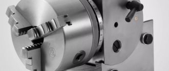
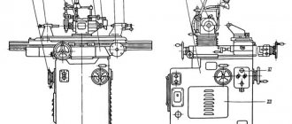
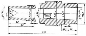
The UDG-D-200 dividing head has a cast iron base 16 with tie rods 17, on which a housing 18 is installed. By loosening the nuts 19 (Fig. 3), you can rotate the housing to a certain angle. The rotation angle is measured using the scale and vernier 20 (see Fig. 2).
On the supporting plane of the base of the dividing head there are two keys that are precisely fitted parallel to the spindle, which are used to install the head in the groove of the milling machine table. The housing contains a spindle with a through hole. The ends of the spindle are bored to a Morse taper. A center 21 is installed at one end, and a mandrel 13 (see Fig. 1) for differential division is installed at the other. The front end of the spindle has a thread and a centering belt 22 (see Fig. 2) for installing and fastening a flange with a self-centering chuck or a driver. On the spindle collar there is a dial 9 of direct division, which has twenty-four holes.
On the spindle, in its middle part, sits a worm wheel with a circular groove at the end, into which the end of a clamp 23 mounted in the housing 18 fits. The worm wheel receives rotation from a worm located in an eccentric sleeve. The worm can be engaged or disengaged by turning the eccentric sleeve using handle 24 (see Fig. 3) with sector 25.
The dividing disk is mounted on a shaft mounted in sliding bearings in cover 26 (see Fig. 2). The cover is fixed on the body 18 with a centering bore and is fixedly attached to the base.
Bevel and cylindrical gears are installed on the shaft of the dividing disk, as well as a drive bar that has a handle with a lock that moves along the required row of holes on the dividing disk. A sliding sector 27, consisting of rulers 28 and a clamping screw 29, is pressed to the dividing disk using a spring, with the help of which the rulers are installed at the required angle. The spring washer prevents spontaneous rotation of the sector.
The mechanical drive shaft 30 from the machine is mounted in plain bearings and located in a sleeve 31 with a flange. The sleeve is attached to cover 26. At the end of the shaft there is a bevel gear, which is in constant mesh with the bevel gear sitting on the shaft of the dividing disk. The dividing disk is fixed in the required position with stopper 7.
Tailstock
The tailstock serves to support the second end of the workpiece when installing it in the centers or chuck of the dividing head. The center of the headstock can be moved in horizontal and vertical directions. At the base 32 there is a housing 33, which is connected to the rail by a pin. By rotating the head of the gear shaft, the housing can be raised, lowered and rotated relative to the axis of the pin. In the required position, the tailstock is secured to the machine table using bolts and nuts.
The movement of the quill 34 with the half-center 35 is carried out by rotation of the handwheel 36 mounted on the screw.
On the supporting plane of the base there are two guide keys, aligned with the axis of the quill; The keys ensure that the centers of the dividing head and the tailstock coincide when they are installed on the machine table.
Lunette
The steady rest is an additional support when processing long and thin parts. In its body 37 there is a screw that moves with the help of a nut 38. The screw has a prismatic head 39; with the help of a locking screw 40 the head can be secured at the required height.
Advantages
Working with the dividing head of a milling machine allows you to:
- • Increase the range of actions performed several times (compared to its absence).
- Ensure the most accurate and current position of the workpiece in relation to the table, both horizontal and vertical.
- • Simplify all operations related to metal objects of various sizes.
In addition, it should be noted the practical advantages characteristic of the equipment itself. So, it is quite reliable and can withstand even intensive use, and therefore is suitable for high-performance facilities. Plus, it is quite easy to learn - with a little practice, it will not be difficult to maintain, especially for an experienced craftsman. Thanks to these advantages, it pays for itself relatively quickly. In modern conditions, this is definitely an important and necessary equipment.
List of controls for the dividing head UDG-200
- Locking handle. Fixing holes on the pitch circle of the pitch disc
- Screw. Fastening the head housing to the base
- Stopper. Spindle lock
- Screw. Fastening the eccentric bushing with a worm
- Eccentric bushing handle. Turning the worm on and off
- Screw. Leash attachment
- Screw. Attaching the locking handle
- Latch. Fixing the direct division dial
- Screw. Attaching the indexing disc stopper pin
- Stopper pin. Locking the dividing disk
- Drive bushing. Guitar mount
- Flywheel. Tailstock half-center movement
- Screw. Tailstock half-center mount
- Cylindrical. Moving the tailstock wheel in the vertical direction
- Bolt. Tailstock housing mount
- Limiter. Aligning holes on the dividing disk when dividing
- Screw. Fastening the bar with handle and lock
UDG-200 Lubrication points of the universal dividing head
Lubrication points of the universal dividing head UDG 160
- I - Disc shaft and bevel gear. Lubricate daily
- II - Cylindrical and bevel gears. Pouring 100 g of oil through the lid
- III - Front spindle bearing. Lubricate daily
- IV - Worm pair. Pouring 200 g of oil into the housing
- V - Rear spindle bearing. Lubricate daily
- VI - Quill and tailstock screw. Lubrication every two days
- VII - Dividing head drive shaft. Lubrication every two days
UDG-200 Kinematic diagram of the universal dividing head
Kinematic diagram of the universal dividing head UDG-200
In simple division, rotation of the spindle 1 is transmitted from the handle 2 with a lock through a pair of spur gears 3, a worm 4 and a worm wheel 5 located in the middle part of the spindle. In this case, the dividing disk 6 must be secured using the stopper 7, and the clamp 8 of the direct division dial 9 is turned off.
In differential division, the angle of rotation of the spindle is determined by the amount of rotation of the handle with the lock relative to the dividing disk and the amount of rotation of the disk itself, which receives rotation from the spindle through the replaceable gears 10 of the guitar 11 and a pair of bevel gears 12. To transmit rotation from the spindle to the replaceable gears of the guitar, a mandrel 13 is used, on the cylindrical neck of which a replaceable gear 14 is installed. In this case, the dividing disk must be released from the stopper, and the direct division dial lock must be turned off.
When cutting a spiral, the spindle receives rotation from the lead screw of the milling machine through the replaceable gears of the guitar, a pair of bevel gears 12, an intermediate shaft 15, cylindrical gears 3, a worm 4 and a worm wheel 5. In this case, the dividing disk must be released from the stopper, and the dial clamp must be directly division is turned off.
Calculation table of divisions
| Division parts | Number of revolutions | Counted holes | Total holes |
| 2 | 20 | — | — |
| 3 | 13 | 11 | 33 |
| 4 | 13 | 9 | 39 |
| 5 | 13 | 13 | 39 |
| 6 | 19 | — | — |
| 7 | 8 | — | — |
| 8 | 6 | 22 | 33 |
| 9 | 6 | 20 | 30 |
| 10 | 6 | 26 | 39 |
| 11 | 5 | 35 | 49 |
| 12 | 5 | 15 | 21 |
| 13 | 5 | — | — |
| 14 | 4 | 24 | 54 |
| 15 | 4 | — | — |
| 16 | 3 | 10 | 30 |
| 17 | 3 | 3 | 39 |
| 18 | 2 | 42 | 49 |
| 19 | 2 | 18 | 21 |
| 20 | 2 | 22 | 33 |
| 21 | 2 | 20 | 30 |
| 22 | 2 | 28 | 39 |
Operating procedure
Direct division
Direct division is used when dividing a circle into 2, 3, 4, b, 8, 12 and 24 parts in cases where great accuracy is not required.
When dividing directly, you must:
- disengage the worm from engagement with the worm wheel by turning handle 24 (see Fig. 3) until it stops
- release the direct division dial clamp from engagement
The spindle is turned by hand by rotating the workpiece or chuck. The angle of rotation is measured using a degree scale marked on the direct division dial and a line on the front spindle bushing.
Secure the spindle in the required position using clamp 23 (see Fig. 2).
When dividing into parts or faces, the calculation is made using the formula
N = 360°/a(1)
where n is the number of parts or faces; A
a is the spindle rotation angle.
Simple division
A simple division of a circle into equal and unequal parts is carried out with a stationary dividing disk using a handle with a lock. The amount of rotation of the handle is measured by the holes on the dividing disk and is fixed with a locking rod.
Differential division
Dividing a circle into a number of parts greater than 42, not a multiple of the number of holes on the dividing disk, can be done by a differential method, the essence of which is that the angle of rotation of the spindle is determined by the amount of rotation of the handle with the lock relative to the dividing disk and the amount of rotation of the disk receiving rotation from the spindle through replacement guitar gears.
The guitar is mounted on a cylindrical shank on which it can be rotated and secured in the desired position. To install replacement gears, the guitar is equipped with movable pins and adapter bushings. To transmit rotation to the replaceable gears, a mandrel is inserted into the rear cone of the spindle, onto the cylindrical neck of which the replaceable gear is installed.
Before starting work, turn the handle to check the smooth rotation of all installed gears.
When performing differential division, the indexing disk stop must be turned off.
The adjustment procedure for differential division is the same as for simple division.
Differential division is only possible with the spindle in a horizontal position.
Spiral Grooving
Milling of spiral grooves is carried out by longitudinal movement of the milling machine table and simultaneous rotation of the part fixed in the dividing head relative to its axis. For coordinated rotation of the part with longitudinal movement of the table, a guitar is installed with a set of replaceable gears that transmit rotation from the machine lead screw to the dividing head spindle.
Procedure for setting up and using
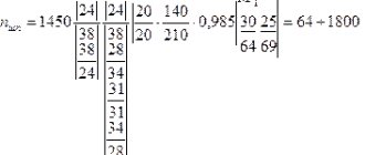
How to use the dividing head on a milling machine and make transitions? This depends on the model purchased, the scale division price and other characteristics. Current standards are also important: for parts of accuracy class VIII you should be guided by the data of GOST 1.758, for IX - 1.643.
In general, preliminary debugging and preparation for operation comes down to choosing a sector based on the diameter of the circle and the required number of parts. You need to do the following:
- • convert a full cycle (360 degrees) into the required number of steps;
- • calculate the appropriate sine of the angle;
- • rotate the disk by the just found radial value;
- • fix the body with a clamp (or the handle of the unit) and place the main tool in this position.
Typically, manufacturers in their instructions indicate the formula by which the angle of the dividing head is calculated, so let’s see how to work with UDG further, let’s not dwell only on calculations, let’s move on to practice.
So, it is necessary to install the workpiece in the machine’s mandrel and, with longitudinal feed, carry out the desired operation. There is a step to consider, which depends on what kind of task is being performed. For example, when creating teeth, the discrete movement must be equal to the distance between the cavities of adjacent elements.
Productivity can be increased without compromising quality by returning the table to its original position in an accelerated manner. The most reliable way to fix it in the disk hole is with a spring.
Technical characteristics of the head UDG-200
| Parameter name | UDG-160 | UDG-200 | UDG-250 | UDG-320 |
| Main settings | ||||
| Accuracy class according to GOST 8-82 | P | P | P | P |
| Center height, mm | 85 | 105 | 130 | 165 |
| Largest diameter of the workpiece, mm | 160 | 200 | 250 | 320 |
| Distance from the base of the dividing head to the end of the spindle in its vertical position: no more than, mm | 180 | 235 | 280 | 350 |
| Angle of rotation of the spindle in the vertical plane down from the center line: not less than, degrees | 5 | 5 | 5 | 5 |
| Angle of rotation of the spindle in the vertical plane upwards from the center line: not less than, degrees | 95 | 95 | 95 | 95 |
| Takar chuck diameter, mm | 100 | 125 | 160 | 160 |
| Spindle taper | Morse No. 2 | Morse No. 3 | Morse No. 4 | Morse No. 5 |
| Spindle end thread | M33 | M39 | M52 | M60 |
| Spindle hole diameter, mm | 14,9 | 20,2 | 26,5 | 38,2 |
| Worm gear ratio | 1 : 40 | 1 : 40 | 1 : 40 | 1 : 40 |
| Division range including prime numbers | 2..400 | 2..400 | 2..400 | 2..400 |
| Diameter of holes for replacement wheels, mm | 20x19 | 20x19 | 20x19 | 32x19 |
| Number of dividing disk holes | 16,19,23 30,33,39 49 | 16,17,19 21,23,29 30,31 | 16,17,19 21,23,29 30,31 | 16,17,19 21,23,29 30,31 |
| Number of dividing disc holes on the other side | 17,21,29 31,37,41 54 | 33,37,39 41,43,47 49,54 | 33,37,39 41,43,47 49,54 | 33,37,39 41,43,47 49,54 |
| Dividing value of the direct division dial, deg | 15 | 15 | 15 | 15 |
| Replaceable gear module | 1,5 | 1,5 | 1,5 | 2,5 |
| Width of guide keys, mm | 12 | 14 | 18 | 18 |
| Dimensions and weight of the dividing head | ||||
| Overall dimensions of the head base, mm | 212 x 156 | 260 x 180 | 260 x 180 | 290 x 234 |
| Dividing head weight, kg | 35,5 | 50 | 53,5 | 101 |
- Universal dividing heads UDG N-100, UDG N-135, UDG N-160 Instructions for use, 1970
- Universal dividing heads UDG D-160, UDG D-200, UDG D-250, UDG D-320, UDG D-400 Technical description and operating instructions, 1983
- Universal dividing head UDG-D-160A Passport, (TU2-024-4475-75)
- Teplitsky B.M. Mazo G.I. Dividing mechanisms, 1974
Bibliography
Related Links. Additional Information
- Milling machines: general information, classification, designation
- Comparative characteristics of cantilever milling machines of the 6N, 6M, 6R, 6T
- Feed box for console milling machines of the 6M : 6M12P, 6M13P, 6M82, 6M83, 6M82Sh, 6M83Sh
- Feed box for console milling machines of the 6P : 6P12, 6P13, 6P82, 6P83, 6P82Sh, 6P83Sh
- Feed box for console milling machines 6T : 6T12, 6T13, 6T82, 6T83, 6T82Sh, 6T83Sh
- Milling machine repair technology
- Adjustment of milling machines
- Friction clutch. Friction shaft. Friction clutches in metal-cutting machines
- Automatic cycles of milling machines (6P12)
- Testing and checking metal-cutting machines for accuracy
- Directory of universal milling machines
- Manufacturers of metal-cutting machines in Russia
- Manufacturers of milling machines in Russia
Home About the company News Articles Price list Contacts Reference information Interesting video KPO woodworking machines Manufacturers
DIY dividing disk - Metals, equipment, instructions
Increasing the functionality of production equipment is possible after installing a dividing head. It is necessary for the production of complex parts and workpieces. This component is often included by default. If it is missing, it is necessary to correctly select the optimal model.
Purpose of the dividing head
To form a part of the desired shape, it may need to be offset relative to the axis of the machine. This can be done using a dividing head. It can be either a separate part of the structure or its component.
The component is mounted on the equipment frame. It has various options for fixing the product, which depend on the type of attachment. The position is adjusted using several handles and a dial. The latter has holes that fix the position of the dividing component.
A similar tool may be needed to perform the following processes:
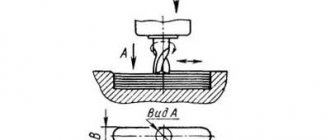
- milling grooves on the surface. This does not require great precision. It is important to control the depth and width of the workpiece;
- formation of edges on parts. This is true for non-standard nuts, tools, and shanks. The operation requires high precision;
- milling splines and grooves. This often requires significant displacements of the workpiece. Therefore, you should choose a dividing disk model with a minimum error rate.
To increase the speed of work, the part should not be constantly dismantled. Changing its position relative to the machine cutter occurs using the tool described above. Particularly difficult is the formation of helical grooves. This operation can only be performed using an accurate model.
Before purchasing a dividing head for a specific type of equipment, you must check its compatibility with the machine. Any independent alteration of the installation part may affect the quality of the product.
Types of dividing head
Multi-function dividing head
Considering the specifics of the application, you should familiarize yourself in detail with the types and general classification of dividing heads. They are mandatory for universal milling machines. The configuration of horizontal milling machines is carried out only when it is necessary to perform complex work.
First of all, you need to decide on the types of work performed on the machine. Particular attention is paid to the accuracy of their implementation. The next parameter is the complexity and accuracy of setting up the equipment for operation. Depending on these factors, you can select models with high accuracy and acceptable error rates. In some cases, such a device is made independently.
There is the following classification of milling dividing heads:
- simple. A special feature is its simple setup and ease of control. The main component is the spindle, on which the workpiece is attached on one side, and the second is connected to a special disk (limbo). The surface of the latter has holes (from 2 to 24). With their help, the part is shifted relative to the milling axis;
- combined. Control occurs using a handle. The greater the number of clicks, the greater the distance between the central axis of the workpiece and the cutting tool. Used for the manufacture of complex parts;
- universal. They are a complex technological complex, the adjustment of which is carried out both using the switching number of the handle and during the movement of the disk itself. This is done by a system of gears. This type of DG is called differential.
It is also recommended that you familiarize yourself with the accepted labeling. It will help you determine the optimal model and find out its parameters. As an example, we can consider the decoding of the name UDG-40-D250:
- UDG. This device designation is Universal Dividing Head;
- 40 – gear ratio value. It shows how many turns of the handle the spindle will rotate 360°;
- D250 is the maximum permissible size of the workpiece being processed.
UDG class models are most often used to form complex edges and surfaces. They are made to order or are components of universal milling machines.
Rarely encountered optical types are marked ODG-5, where 5 is the price of one division in seconds.
Technical characteristics of UDG
| Head | UDG 400 | UDG 320 | UDG 250 | UDG 160 | UDG 125 |
| Workpiece diameter, mm | 400 | 320 | 250 | 160 | 125 |
| Worm pair | 1 in 40 | 1 in 40 | 1 in 40 | 1 in 40 | 1 in 40 |
| Diameter of replacement wheels | 32 x f9 | 32 x f9 | 20 x f9 | 20 x f9 | 20 x f9 |
| Spindle diameter, mm | 38,2 | 38,2 | 26,5 | 14,9 | 20,2 |
| Dial division price | 15 | 15 | 15 | 15 | 15 |
| Chuck diameter, mm | 200 | 160 | 160 | 100 | 125 |
| Key width, mm | 22 | 18 | 18 | 12 | 14 |
| Weight, kg | 106 | 101 | 536,6 | 25 | 28 |
UDG 400 UDG 320 UDG 250 UDG 160 UDG 125
Calculation table of divisions
| Division parts | Number of revolutions | Counted holes | Total holes |
| 2 | 20 | — | — |
| 3 | 13 | 11 | 33 |
| 4 | 13 | 9 | 39 |
| 5 | 13 | 13 | 39 |
| 6 | 19 | — | — |
| 7 | 8 | — | — |
| 8 | 6 | 22 | 33 |
| 9 | 6 | 20 | 30 |
| 10 | 6 | 26 | 39 |
| 11 | 5 | 35 | 49 |
| 12 | 5 | 15 | 21 |
| 13 | 5 | — | — |
| 14 | 4 | 24 | 54 |
| 15 | 4 | — | — |
| 16 | 3 | 10 | 30 |
| 17 | 3 | 3 | 39 |
| 18 | 2 | 42 | 49 |
| 19 | 2 | 18 | 21 |
| 20 | 2 | 22 | 33 |
| 21 | 2 | 20 | 30 |
| 22 | 2 | 28 | 39 |
Self-production
Homemade dividing head
One of the disadvantages of factory models is their high cost. Therefore, to perform simple operations, a homemade structure is made. For practical implementation, certain components will be required.
First of all, you will need a worm gearbox. You can pick it up from used machines or grind it yourself. It is also necessary to use a lathe chuck (optimal diameter 65 mm) and a dial. The latter can be taken from old drawing drawing boards. To limit processing, it is recommended to install a locking screw.
Before you start making parts, you need to configure the divider. To do this, you can take any standard part and carve any shape. After comparing it with a similar one, additional adjustment is performed.