Surface cleanliness during turning depends on the depth and speed of cutting, the quality of the workpiece material and other characteristics. Finish turning and grinding make it possible to obtain a part with the required degree of roughness.
Metal processing is the main type of work that allows you to obtain the necessary part with specific specified technical parameters. The technique of working on a lathe is aimed at removing an excess layer of metal from a workpiece to give the part the desired geometric shape and size. Additionally, during the processing process, the desired surface is formed (the texture can be achieved by grinding). Lathes belong to the class of metal-cutting industrial units, where various cutters are used for turning and processing.
During the work, the following types of metal parts and components can be obtained: bushings, threaded nuts, shafts, gears, cylinders, rings of various diameters and other components of rotating mechanisms. Turning work is carried out in various fields of industrial activity. Lathe units are installed in large manufacturing enterprises, workshops or even home workshops. Previously, the processing process was carried out manually - all work was done mechanically.
Modern turning equipment is equipped with a computer program system, which allows processing and grinding processes to be carried out with maximum automation. The specified programs are aimed at the most accurate turning of metal workpieces, as a result of which the dimensions correspond to the specified ones down to hundredths of a millimeter.
Grinding heads for lathes
Modern trends in the integration of combined machining have meant that grinding can also be carried out on lathes. When quality problems come to the fore, attention is always paid to the finishing process, which is called grinding - performing mechanical action in several passes to reduce initial errors. It is impossible to carry out finishing using a turning tool with the same quality as when using grinding heads due to the rounding of the cutting edge. Also, do not forget that vibration may occur on a lathe at small feeds, which will lead to errors. For this reason, even with the emergence of new materials that can withstand heavy impact for a long time and not change their shape, grinding remains the main method used to obtain a surface of a high class of roughness.
Requirement for grinding heads
The production of rotating bodies on lathes has been carried out over the past several decades. As a rule, grinding was carried out using other equipment. This moment was determined by the following technological process:
- performing rough turning to remove a large layer of metal;
- performing fine turning to prepare the part for the finishing stage of the technological process;
- finishing on a cylindrical grinding machine.
Such a technological process determines an increase in costs due to the installation of a special machine for finishing processing. When creating a large batch of products, purchasing a grinding machine pays off, but in small-scale production, its purchase will lead to an increase in the cost of one product. A way out of the situation is the use of special grinding heads, which can also be used to obtain a surface with a high roughness class.
Design Features
Grinding heads are a special design that is used to significantly expand the capabilities of a turning group machine. This mechanism conventionally refers to equipment. Design features include:
- the presence of its own electric motor, the power of which can be from 1 kW or more. This point determines that the head can become equipment for various models of lathes. as a rule, turning equipment has a closed gearbox and does not have a separate drive for connecting the equipment in question;
- the installed electric motor is connected to the lathe circuit, which determines the versatility of the entire structure. there is also a three-phase plug for inclusion in a separate power circuit;
- the head has its own frame, which, during modernization, can be rigidly attached instead of a standard tool holder. This point determines that the equipment makes it possible to obtain high-quality surfaces with high mechanization of the process. steel is used in the manufacture of the frame, which helps prevent vibration during operation by increasing the rigidity of the structure;
- rotation is transmitted using a belt drive to reduce speed.
The design is quite simple. When considering it, it is worth paying attention to the type of frame. This is due to the fact that only a certain type of bed can be used instead of a tool holder for a certain model of lathe.
Grinding head VGR 150
There are several popular models of cylindrical grinding heads, among which we note the VGR 150. It has the following features:
- comes with an external grinding spindle with a wheel diameter of 125 millimeters;
- the VGR 150 version can also be used for grinding internal surfaces with a wheel with a diameter of 8 to 40 millimeters;
- The model can be installed on a lathe with a pin diameter for the tool holder of no more than 22.5 millimeters. at the same time, the VGR 150 frame has a contact surface of 202 by 102 millimeters;
- for external grinding, the spindle speed at idle is 5000 rpm, for internal grinding - 16,800 rpm at idle. during operation, the indicator can decrease significantly, which depends on the value of the cross feed. with a strong feed, there is a possibility of the belt slipping on the installed pulleys, which eliminates the possibility of displacement of the output shaft of the electric motor relative to the windings, as well as its deformation;
- VGR 150 drive shafts are mounted on precision bearings;
- the spindle sleeve and motor base are adjustable, which greatly increases the versatility of the device;
- using a belt drive, you can adjust the rotation speed of the circle depending on the tasks assigned; as a rule, there are 2 gears;
- VGR 150 can be used to obtain dimensions with an accuracy ranging from 0.01 to 0.02 millimeters. this point determines that model 150 and 200 can be used to obtain a highly clean surface.
The maximum diametrical size of the workpiece when using VGR 150 is limited by the longitudinal movement of the support and depends on the features of the lathe.
Using the equipment in question, steel and cast iron can undergo finishing on a lathe. In this case, it is possible to achieve the same roughness index as when using cylindrical grinding equipment. Model 200 differs from the considered power of the installed electric motor and the maximum diametrical dimensions of the installed circles. Similarly, the cost of producing parts can be reduced by increasing the versatility of the equipment used. At the same time, we note that the equipment is suitable for old and new turning equipment, as it has universal application.
How to properly organize a workplace
The turning specialization of a master requires from a specialist not only practical knowledge, but also professional knowledge of theory. Qualification in metal processing using this type of equipment requires you to properly organize your own workplace. This zone is the entire area of the production workshop, within which there is one or more types of machines of this type.
In addition to grinding and turning machines, the room should be equipped with separate cabinets where you can store auxiliary things: technical instructions, tables, reference books. Lubricants and coolants (if necessary) should be kept near the immediate workplace. According to fire safety rules, there must be a fire extinguisher in the room that meets the standards in terms of power and volume.
It is recommended to use the following household items for cleaning and removing chips: turning oiler (suitable for storing lubricating oil), brushes, scoops, wiping materials (used for grinding). It is also necessary to arrange a seating area with chairs and stools.
The temperature in the work shop or workshop should be no more than 25 degrees Celsius according to fire safety standards. As temperatures rise, metal parts can expand, causing mechanisms to jam. Cutters for the workpiece being processed and other sharp objects should not be in an unfixed position. Special tool boxes are designed for them. For convenience and to avoid vibration, a wooden base should be laid in front of the machine. In modern industrial centers, a rubberized floor can be used, eliminating any vibrations in the room. For previous generations of equipment, it is necessary to protect yourself from the risk of shocks. This can lead to incorrect feed of the cutter to the processed workpiece when the machine is running. When using grinding equipment, it is recommended to use durable gloves that protect exposed skin from the negative effects of moving elements.
It is unacceptable to have any uncleaned dirt or shavings before starting the process. Some coarse particles may have entered the mechanism and there is an increased risk of them flying out or scattering during the process. The lack of work uniform and safety glasses can lead to injuries of varying severity. The workplace should be cleaned after each shift. In constant operation, it is important to clean the equipment from chips and coarse particles every few hours.
The standards described above are optional (except for the need to have a fire extinguisher). However, every turning laboratory or workshop must comply with established safety regulations. These standards are studied by qualified personnel before taking up their positions. The remaining parameters and requirements regarding workplace equipment are formed and prepared based on various factors: the size of the workshop, the amount of equipment, the dimensions of production, the shape of workpieces, and the type of company.
Devices for fixing workpieces
For fastening workpieces, universal devices are used - centers, bushings and mandrels. Centers are used for parts longer than three meters with base surfaces in the form of center holes. Depending on the design, they are divided into rotating and stationary, and are installed in the headstock and tailstock quills. The angle of the front center taper depends on the type of work. For normal operations it is 60°, for heavy work - 90°. The material is tool steel with a hardness of HRC 55-58.
There are various design options for centers to perform special operations:
- Grooved centers for processing hollow workpieces.
- Centers with undercut. Used for end cutting.
- Spring-loaded or “floating” centers – for precise installation of parts along the end.
The figure above shows the designs of the centers: a - ordinary; b - corrugated; c - with recess, d - rotating for workpieces with central recesses; d - rotating for workpieces with conical ends.
In the event that a part cannot be fixed in the chuck, for example due to an irregular geometric shape, a special device is used for securing workpieces on machines - a faceplate. This is a flat disk with radial or concentric grooves, which is attached to the machine spindle through a flange. The grooves can have a T-shaped or figured shape in cross section. The workpiece is centered and fixed on the faceplates using replaceable clamps and adjustments.
For turning some workpieces with internal through holes, fixation using a mandrel is used. These devices are divided into center and spindle. In turn, center ones are divided into solid and expanding.
The figure above shows the mandrels in section: a - center; b - spindle; 1 - rod; 2 - workpiece; 3 - split element; 4 - nut.
Additional supports
When processing workpieces of large length and small diameter, additional supports - rests - are used to ensure reliable fixation. They are necessary to increase the rigidity of the workpieces being processed. Depending on the design, the rests can be:
- mobile;
- motionless;
- modernized with a self-aligning coupling;
- self-aligning, with bearings built into the cams.
Fixed devices are used for processing shaft blanks whose length exceeds 10 product diameters. Before installing the steady rest, it is necessary to secure the workpiece in the centers and machine the neck for the cams. The steady rest itself consists of a cast iron body with a hinged lid to facilitate fixation of the workpiece. The body is attached to the frame with a strap and a bolt. The cams are moved using adjusting screws, and special screws are used to fix them in the desired position. Some designs use rollers instead of cams to reduce friction.
Movable rests are installed directly on the caliper carriage. This attachment is also used for turning long shafts, in particular for finishing, threading and other operations. The adjustable cam system allows the steady rest to be adjusted to the shaft size.
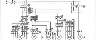
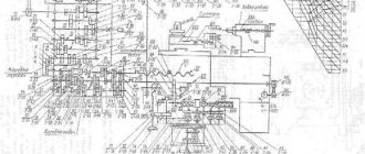
Location of controls for thread grinding machine 5822
Location of controls for thread grinding machine 5822
List of controls for thread grinding machine 2A106P
- switch for connecting and disconnecting the machine from the electrical network;
- handle for starting, reversing and stopping the table and spindle of the product;
- push-button control panels for electric motors;
- compartment for replaceable gears;
- guitars for adjusting thread pitch and differential (under the cover);
- handle for turning on the back movement;
- handle for turning on the table stroke (link for increasing the thread pitch);
- product speed tachometer;
- guitar for backing adjustment (under the cover);
- screws with a dial for correcting the thread pitch;
- a screw with a dial for inserting a circle into the thread;
- coolant pipeline valve;
- cams for automatically stopping the table during plunge-cut grinding (under the cover);
- handle for quick removal and supply of the grinding head;
- cross feed flywheel;
- fine cross feed dial;
- ruler for grinding tapered threads;
- cams for automatic table stop;
- gap compensator for adjusting double-sided grinding (under the cover);
- roller for manually turning the product spindle (under the cover);
- machine lubrication button;
- replaceable device for straightening and rolling the wheel (under the cover);
- control panel for an automatic wheel dressing device and a wheel rolling device;
- plug socket for center sanding fixture;
- clamping handle of the mechanism for inserting the wheel into the thread of the thread being ground.
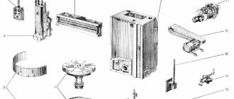
Milling and grinding accessories
In modern metalworking, devices for milling the surface of the workpiece are widely used. With its help, you can select grooves and grooves, contour processing and milling planes. The fixture can be equipped with face and end mills for the corresponding operations.
Special grinding devices are used in piece and small-scale production, when it is not economically feasible to purchase a special machine for this operation. The grinding device has its own electric motor which is connected to the lathe circuit. The head of the device has its own frame, which is attached instead of the tool holder. Rotation is carried out using a belt drive.
The use of various devices allows you to use the full potential of the lathe and is economically justified in terms of reducing operating costs.
What are the types of professional machines of this type?
Turning equipment can be as follows:
- Screw-cutting lathes;
- Turret lathes;
- Carousel equipment;
- Lathe units.
These industrial units have different levels of automation and mechanical structure.
The first version of lathes is designed for forming threaded surfaces on metal workpieces and processing them during rotational actions of the workpiece (forming cylinders, cones, cutting internal holes). It consists of several key elements. The bed is a large and durable base (usually made of cast iron or other heavy metal). The rest of the equipment is attached to it. The headstock moves along two parallel guides along with the caliper. The spindle allows you to attach the necessary attachment to the equipment for further processing of the workpiece. It is secured using a special chuck, which is installed on the right side of this part. The support provides not only fixation of the nozzle (cutter), but also its controlled control for precise processing of the installed metal workpiece.
If the machine has completely mechanical controls, then levers are used for controlled movements of the cutter. The gearbox is controlled in the same way, and the process of turning the lathes on and off is carried out using special keys.
A turret-type machine also allows for boring, reaming, countersinking, turning workpieces with cutters and giving them different geometric shapes. The name of this equipment comes not from the processing technology, but from the method of attaching the cutter (attachment). The turret holds the cutter using a special block. Due to this, the functionality of the equipment is expanded.
Lathe units differ in the axis for securing the workpieces. It is installed horizontally, due to which processing is not carried out longitudinally. This allows you to easily process round cylinders, tapered shafts or pipes made of different materials. Here the turning process is carried out in a similar way as in turret or screw-cutting equipment. The difference lies in the general design of the key components. In some cases, these machines can be used for grinding processes to create the desired texture on a workpiece of the desired shape.
Carousel equipment is used for processing large workpieces that do not fit into standard-sized machines. They allow you to process metal in the same way as other units of this type, but the potential size of the workpiece can be significantly increased. To do this, a cutter of the required shape is installed in the chuck.
Types of accessories for the machine
There are different types of lathe attachments. Accessories for lathes are produced in a wide range. This makes it possible for the master to choose the best option in accordance with the task.
Vibration mounts
Vibration mounts (aka vibration isolators) are designed for active or passive vibration isolation of different types of machines: small, medium or large. The use of vibration supports will help improve the quality of parts processing.
Centers
Lathe centers are used to fix the workpiece, which has a body of rotation on the tailstock of the lathe. The center allows you to process parts at high speed and with minimal runout.
Ammo
These are devices for accurately securing a workpiece on a machine. Thanks to the use of lathe chucks, the functionality of the machine itself is significantly increased, and it also becomes possible to process complexly shaped parts. Mainly used to secure workpieces for metal cutting operations.
Fists
Lathe jaws can be:
- Straight - needed to clamp the workpiece from the outside for the shaft.
- Reverse - necessary for clamping the workpiece only from the inside.
- Overlays - necessary for fastening long or short workpieces of large diameters.
Typically, turning jaws are made of non-ferrous metals and steel without heat treatment.
Jaw chucks
Specialized for clamping rectangular and cylindrical workpieces.
- Two-jaw - necessary for securing complex workpieces with shaped parts. Double-jaw attachments can clamp a variety of surfaces into interchangeable jaws.
- Three-jaw chucks are one of the most common cartridges. They are installed on almost any lathe. In turn, they are divided into three types:
- Spiral.
- Rack and pinion.
- Eccentric.
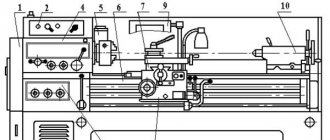
Machine layout
The base of the machine is a cast iron frame (column 100), on which all the main components of the machine are mounted (Fig. 4).
At the left end of the table (gr. 110), moving along the rolling guides, a headstock (gr. 400) is mounted. An electric motor is installed on the headstock to drive the product spindle, move the table and backing movement of the grinding headstock (gr. 361), connected by gear wheels to the feeding mechanism of the dressing devices (gr. 671).
In the left niche of the front part of the frame there is a pumping unit for lubricating the machine - a reservoir, a pump and a filter.
In the right niche of the front part of the frame there is a pumping unit for lubricating the grinding spindle - a reservoir, a pump, a filter and a float relay.
Electrical equipment and electrical wiring of the machine are mounted in the niches of the rear part of the frame.
A lead screw with a mechanism for correcting the pitch of the ground thread is mounted at the bottom of the table. The movable running nut is located on the frame.
A splined shaft (gr. 380) is mounted in the front part of the table (inside it), which transmits rotation from the headstock to the backing mechanism.
In the front niche of the frame there is a mechanism for transverse feeding, backing and conical grinding (gr. 300).
The rotating unit of the grinding spindle (gr. 220) is mounted on the vertical front wall of the grinding headstock housing. An electric motor for driving the grinding wheel is installed on the rotary segment located at the rear end of the headstock housing. In the niche of the headstock, behind the grinding wheel, replaceable devices for dressing single- and multi-thread wheels are installed. Each of the devices is fixed on the slide of a common mechanism along with the ruling devices. At the bottom of the headstock there is a mechanism for compensating feedstock feed. Under the casing, hung on the left side of the frame, an electric machine amplifier (an electric motor and a DC generator mounted in one housing) is installed on the floor to supply current to the headstock electric motor.
On the right side of the machine there is a unit consisting of a cooling oil tank, a cooling pump, a magnetic separator, a filter and a suction fan.
Rules for using mandrels
There is a list of rules for using turning mandrels:
- The accuracy of the mounting hole must be no lower than the seventh quality, and the surface cleanliness must be no worse than Ra 1.0.
- The tool must be positioned along the center axis of the machine.
- The contact surface of the turning mandrel should be maximum.
- To avoid deformation and deformation of the tool during the cutting process, the hardness of the holder collet material should not be less than 44 HRC.
- The greater the overhang of the mandrel, the more securely it must be secured. It is strictly forbidden to fasten long mandrels by pressing screws to a cylindrical or other surface. To install long mandrels, it is necessary to use additional equipment.
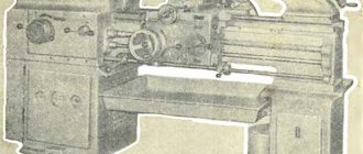
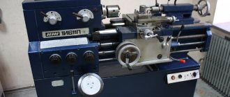
General view and general structure of the machine 5822
Photo of thread grinding machine 5822
Photo of thread grinding machine 5822
Photo of thread grinding machine 5822
Photo of thread grinding machine 5822
Grinding heads of lathes: drawings, VGR-150
Grinding head VGR-150-ChR with speed control.
Materials such as steel or cast iron, regardless of heat treatment level, can be ground on a lathe using this accessory in the same way as on a cylindrical grinder.
In addition, the presence of smooth adjustment of the rotation speed makes it possible to ideally select processing modes when polishing stainless steel and non-ferrous metals.
This can therefore reduce your capital investment by increasing the versatility of your existing equipment.
The main advantages of the VGR-150-ChR grinding head:
- the grinding spindle shaft rotates in precision angular contact bearings;
- The external grinding spindle is driven by a V-belt;
- The internal grinding spindle is driven by a flat belt,
- The rotation speed of the spindles is regulated by simply rotating the handle and is selected smoothly, depending on the type of task.
- the ability to grind working surfaces from 10 mm in internal diameter (largely depends on the grinding stone mandrel) and up to a minimum of 8 mm for external grinding. The maximum diameter of the external grinding depends on the dimensions of your lathe, but it is recommended, for reasons of efficient performance, no more than 350 mm.
- accuracy within 0.01 – 0.02 mm;
- high surface cleanliness;
Grinding heads for lathe. VGR-150-VSh (internal grinding)
To expand the capabilities of the lathe, special mechanized equipment is produced - the VGR-150 grinding head. It consists of a 1.1 kW electric motor connected to the power supply of the lathe, a bed installed on a universal lathe instead of a standard tool holder, and a high-speed spindle.
In this configuration, the VGR-150 head has one spindle for internal grinding. Internal grinding is carried out using abrasive grinding attachments with a diameter of 8 to 40 mm. Internal grinding attachments - cutters are glued to the mandrel included in the spindle kit.
Information about the manufacturer of thread grinding machine 5822
Manufacturer of thread grinding machine 5822 Moscow plant of jig boring machines "MZKRS" , founded in 1942
Machines produced by the Moscow plant of jig boring machines MZKRS
- 2A450
- jig boring machine 630 x 1100 - 2D450
- jig boring machine 630 x 1120 - 2E450
jig boring machine 630 x 1120 - 2E450AF1
jig boring machine 630 x 1120 - 2E450AF30
jig boring machine with CNC630 x 1120 - 5K822V
– universal high-precision thread grinding machine Ø 150 - 525
— semi-automatic gear cutting machine for cutting spiral bevel wheels Ø 500 - 2450
— jig boring machine 630 x 1100 - 5822
universal thread grinding machine Ø 150 - 5822m
universal thread grinding machine Ø 150