Information about the manufacturer of the universal sharpening machine 3E642
The manufacturer of the universal sharpening machine 3E642 is Vitebsk sharpening machine plant Visas , founded in 1897.
Since 1940, the company has specialized in the production of sharpening equipment and today is the only manufacturer in the CIS of machines for the manufacture and sharpening of any cutting tool. The plant's products are used in more than sixty countries around the world.
Machines produced by the Vitebsk sharpening machine plant, Visas
- 3A64
- universal sharpening machine Ø 250 x 650 - 3A64M
- universal sharpening machine Ø 250 x 650 - 3A64D
- universal sharpening machine Ø 250 x 600 - 3A662
- semi-automatic grinding machine for hob cutters Ø 200 x 280 - 3B642
- universal sharpening machine with hydraulic drive Ø 250 x 630 - 3B642
- universal sharpening machine Ø 250 x 630 - 3D641E
universal sharpening machine with hydraulic drive Ø 200 x 400 - 3D642E
- universal sharpening machine with hydraulic drive Ø 250 x 630 - 3E642
- universal sharpening machine Ø 250 x 630 - 3E642E
- universal sharpening machine with hydraulic drive Ø 250 x 500 - 3M642
- universal sharpening machine Ø 250 x 500 - 3D692
- universal sharpening machine for circular saws, semi-automatic Ø 275..1430 - 3E692
- universal sharpening machine for semi-automatic circular saws Ø 250..1430 - 3662
— grinding machine for hob cutters, semi-automatic Ø 125 x 200 - VZ-318, VZ-318E
- universal sharpening machine Ø 200 x 500 - VZ-818, VZ-818E
- universal sharpening machine Ø 200 x 500 - VZ-319
– universal tabletop sharpening machine Ø 100 x 200 - BDS-4
- combined wood cutting machine - BDS-5
- combined wood cutting machine
Machine 3E642E. Universal sharpening. Manual. Electrical equipment
This instruction manual for the “Universal sharpening machine 3E642E” contains information necessary both for the maintenance personnel of this machine and for the employee directly involved in working on this machine. This manual is an electronic version in PDF format of the original paper version. This documentation contains the Manual (instructions) for operating the electrical equipment of the 3E642E universal sharpening machine.
CONTENT
Characteristics of electrical equipment Power system Initial start-up Description of operation
- Operation of the electrical automation circuit of the machine
- Operation of the skid reverse board
Interlocks Alarm system Protection Instructions for safety measures Possible malfunctions and methods for eliminating them
download the operating manual for the electrical equipment of the universal sharpening machine 3E642E in good quality from the link below.
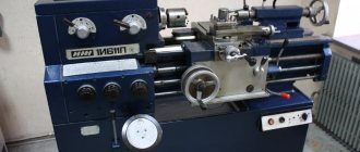
3E642 Universal sharpening machine. Purpose and scope
3E642 universal sharpening machine replaced the outdated model 3D642E
.
3E642 universal sharpening machine is designed for sharpening the main types of cutting tools: cutters, milling cutters, countersinks, etc. made of tool steel, hard alloy, cermets with abrasive, diamond and CBN wheels.
Machine 3E642 (3E642E) replaced the outdated model 3D642E
(3D642E) and was discontinued in 1994. Currently, production of the “legendary” models of sharpening machines 3E642 and 3E642E has been resumed.
Grinding machines 3E642 have a cast iron frame, this increases the accuracy of processing and reduces vibrations caused during processing of the part. Additionally, the machines can be equipped with a sine plate for securing workpieces, a device for radius sharpening of cutters and multi-edge end tools, a device for external cylindrical grinding, for internal grinding, for sharpening right- and left-handed countersinks, etc.
3E642 machine sharpens and refines metal-cutting tools made not only of hard alloy or tool steel, but also of mineral ceramics. Metal-ceramic compounds are characterized by a high tungsten content and high heat resistance. Therefore, sharpening of cermet tools is carried out using diamond and CBN wheels.
The sharpening machine 3E642 performs the following grinding work:
- external and internal cylindrical grinding;
- flat grinding.
Operating principle of the machine
Sharpening a multi-edge tool on a machine can be done using two methods:
- with supply for product turnover;
- with feed on each tooth to a hard stop.
Sharpening with feed to product revolution
Part of the allowance is removed sequentially from each tooth. After the product has been rotated, the wheel is fed again and the cycle is repeated.
Using this method, you can sharpen a multi-blade tool either manually or in an automatic cycle.
Sharpening with feed on each tooth to a hard stop
The allowance is removed from one tooth of the tool, and the position of the cutting part of the grinding wheel is fixed with a rigid stop. Then the circle is retracted, division is made and the operation is repeated on each tooth.
Design and technological features of the sharpening machine 3E642
- impressive technological capabilities with compact dimensions;
- backlash-free table drive from the flywheel;
- cast iron bed allows you to reduce vibrations when processing the part and increase the accuracy of processing;
- the dust extraction system increases the comfort of using the machine;
- a large list of additional devices necessary for the implementation of technical specifications;
- a sine plate installed on the machine allows you to solve many problems;
- turning the grinding wheel motor in the direction opposite to the spindle allows you to significantly speed up readjustment and increase technological capabilities.
The 3E642 machine has the ability to install a wide range of devices on it, in particular for securing workpieces, which allows you to process almost any cutting tool.
The 3B642 machine is manufactured in the following versions:
- with stepless regulation of the rotation speed of the grinding spindle (3e342e);
- with step-by-step speed control of the grinding spindle (3e342).
According to the design of the guides, the machines are manufactured:
- with closed steel guides with preload;
- with open monolithic cast iron guides with preload.
The climatic design and placement category of machines, separately located equipment and accessories comply with GOST 15150-69 for delivery to the areas:
with a temperate climate - UHL4;
Machine accuracy class – P.
History of production of universal sharpening machines
The 3M642 (3M642E) machine is the previous analogue of the 3D642 (3D642E) machines.
The 3D642 (3D642E) machine is the previous analogue of the 3E642E (3E642E) machines.
The 3E642 (3E642E) machine is a previous analogue of the VZ-318 (VZ-318E) and VZ-818 (VZ-818E) machines.
Machines models 3E642 and 3E642E were discontinued in 1994.
Currently, production of the “legendary” models of sharpening machines 3E642E and 3E642 has been resumed.
Machines of the VZ-318 and VZ-318E models were discontinued in 2008.
Machine tools of the VZ-818 and VZ-818E models are currently produced by the plant.
Machine passport 3E642E. Universal sharpening.
This instruction manual for the “Universal sharpening machine 3E642E” contains information necessary both for the maintenance personnel of this machine and for the employee directly involved in working on this machine. This manual is an electronic version in PDF format of the original paper version. This documentation contains the Passport and Manual (instructions) for the operation of the 3E642E universal sharpening machine.
CONTENT
General information about the machine Basic technical data and characteristics
- Technical characteristics of the machine
- Basic data
Scope of delivery Safety precautions
- Safety requirements for transporting and installing the machine
- Safety requirements when working on the machine
Composition of the machine Design, operation of the machine and its components
- Operating principle of the machine
- General layout of the machine
- Principal kinematic diagram
- Description of the design of the individual components of the machine
Lubrication system Installation procedure
- Unpacking and transporting the machine
- Reactivation of the machine
- Installation
- Preparing for initial launch
- Initial launch
Operating procedure
- Setting the grinding wheel speed
- Installing the grinding wheel
- Installing the grinding wheel guard
- Adjusting the axial clearance in the bearing units of the grinding head
- Rotate the grinding head in the horizontal plane
- Rotating the grinding head in a vertical plane
- Rotating the bracket with the electric motor and reinstalling the grinding head
- Vertical movement of the grinding head
- Transverse movement of the grinding head
- Longitudinal movement of the table
- Multi-pass sharpening
- Sharpening a multi-edge tool on the back surface
- Sharpening cylindrical cutters
- Sharpening shank or sheath end mills
- Sharpening reamers
- Sharpening of shaped backed cutters with helical flutes
Possible malfunctions and methods for eliminating them Features of disassembly and assembly during repair Acceptance certificate
- Test results
Preservation and packaging information
- Certificate of conservation
- Packaging Certificate
Instructions for maintenance, operation and repair
- Adjusting the belt drive of the grinding head drive
- Recommendations for choosing cutting modes
download the passport of the universal sharpening machine 3E642E in good quality from the link below.
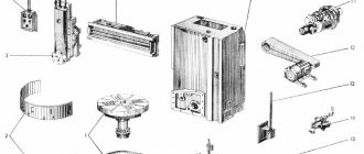
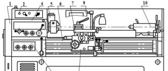
Location of components of the sharpening machine 3E642
Location of components of the sharpening machine 3e642
Specification of components of the sharpening machine 3E642
| No. PP | Name | 3E642E | 3E642 |
| 1 | Machine bed | 3B642E.10.000 | ZB642.10.000 |
| 2 | Table feed hydraulic cylinder | 3E642E.73.000 | — |
| 3 | Desk base | 3E642E.11.000 | 3E642.11.000 |
| 4 | Grinding head | 3E642E.31.000 | 3E642E.31.000 |
| 5 | Table reverse mechanism | 3E642E.43.000 | — |
| 6 | Manual table movement mechanism | 3E642E.41.000 | 3E642E.41.000 |
| 7 | Hydrocommunications | 3E642E.70.000 | — |
| 8 | Main control panel | 3E642E.85.000 | — |
| 9 | Control Panel | 3E642E.15.000 | 3E642.15.000 |
| 10 | Left control panel | 3E642E.83.000 | 3E642.83.000 |
| 11 | Cooling | 3E642E.60.000 | 3E642E.60.000 |
| 12 | Remote control housing | 3E6423.12.000 | |
| 13 | Carriage with column | 3E642E.20.000 | 3E642E.20.000 |
| 14 | Electrical equipment. Position on the machine | 3E642E.80.000 | 3E642.80.000 |
| 15 | Table lifting mechanism | 3E642E.21.000 | 3E642E.21.000 |
| 16 | Grinding head | 3E642E.30A.000 | 3E642E.30A.000 |
| 17 | Set of casings | 3E642E.92.000 | 3E642E.92.000 |
| 18 | Set of mandrels | 3E642E.91.000 | 3E642E.91.000 |
| 19 | Work desk | 3E642E.40.000 | 3E642.40.000 |
| 20 | Fine feed mechanism | 3M642E.26.000 | 3M642E.26.000 |
| 21 | Cross feed mechanism | 3E642E.23.000 | 3E642E.23.000 |
| 22 | Electrical equipment. Panel location | 3E642E.81.000 | 3E642.81.000 |
| Extended grinding head | 3E642E.32.000 | 3E642E.32.000 | |
| Slide reverse block | 3E642E.86.000 | — | |
| Set of tools and accessories | 3E642E.90.000 | 3E642E.90.000 | |
| Right control panel | 3E642E.84.000 | 3E642.84.000 | |
| Fencing | 3E642E.93.000 | 3E642E.93.000 | |
| Dust extraction | 3M642E.94.000 | 3M642E.94.000 | |
| Set of accessories | 3E642E.95.000 | 3E642E.95.000 | |
| Table lift gearbox | 3M642E.25.000 | 3M642E.25.000 | |
| Electrical equipment. Panel location | 3E642E.82.000 | — | |
| Main control panel | — | 3E642.82.000 |
Technical characteristics 3E642
| Parameter | Meaning | |
| Indicators of the workpiece processed on the machine | ||
| The largest diameter of the product installed in the center headstocks, mm | 250* | |
| Maximum length of the product installed in the center headstocks, mm | 630** | |
| Maximum length of the processed surface, mm | 450 | |
| * 330 mm using fixture 3E642EP32 | ||
| ** 1040 mm using devices 3E642E.P61 and 3E642E.P73 | ||
| Indicators of the tool installed on the machine | ||
| The largest diameters of the installed grinding wheel type 1 according to ISO 525-86 (GOST 2424-83), as well as CBN and diamond grinding wheels of similar shape and size, mm | 200 | |
| other types, mm | 150 | |
| Indicators of working and installation movements | ||
| Maximum longitudinal movement of the table, mm | 450 | |
| The largest angle of rotation of the table in the horizontal plane in the middle position, degrees. | ||
| - clockwise | 45 | |
| - counterclock-wise | 45 | |
| The largest angle of rotation of the table in the horizontal plane according to the precision rotation scale, degrees. | ||
| - clockwise | 8 | |
| - counterclock-wise | 8 | |
| Maximum vertical movement of the grinding head, mm | 250 | |
| Maximum transverse movement of the grinding head, mm | 230 | |
| Maximum displacement of the grinding wheel axis in the horizontal plane due to the eccentric plate, mm | 100 | |
| The largest angle of rotation of the grinding head in the horizontal plane, degrees. | 360 | |
| The largest angle of rotation of the grinding head in the vertical plane, degrees. | ||
| - clockwise | 200 | |
| - counterclock-wise | 20 | |
| Indicators of the main and auxiliary movements of the machine | ||
| Limits of rotation speed of the grinding spindle, min -1 | 2800; 4000; 5600; 8000 | |
| Speed of vertical mechanized movement of the grinding head, mm/min | 390 | |
| Indicators of the power characteristics of the machine | ||
| Main drive drive power, kW | 0.71/0.85 | |
| Total power of electric motors installed on the machine, kW | 0.89/1.03 | |
| Other options | ||
| Overall dimensions of the machine (together with separately located units and electrical equipment), mm | ||
| Length | 1380 | |
| Width | 1940 | |
| Height (without lamp) | 1150 | |
| Weight of the machine together with separately located units and electrical equipment), kg | 1200 | |
| Processing roughness indicators (per batch) of sample products | ||
| Grinding with the end of an abrasive wheel, microns | Ra <= 0.32 | |
| Grinding with the end of a diamond wheel, microns | Ra <= 0.08 | |
| Machine accuracy class | ||
| Machine accuracy class according to GOST 8-82 | IN | |
| Universal headstock VZ-318.P1 | ||
| Maximum length of the product installed in the centers of the universal and tailstocks, mm | 360 | |
| Rotation angle, degrees. | ||
| in the horizontal plane | 360 | |
| in the vertical plane | 240 | |
| Inner spindle cone according to GOST 25557-82 | Morse 5AT6 | |
| Number of divisions when working with a dividing disk | 3,4,6,8,12,24 | |
| Front headstock VZ-318.P2 | ||
| Internal cone of the quill according to GOST 25557-82 | Morse 2AT7 | |
| Rear headstock VZ-318.P3 | ||
| Internal cone of the quill according to GOST 25557-82 | Morse 2AT7 | |
| Quill stroke, mm | 20 | |
| Universal support 3E642E.P4 (see previous figure) | ||
| Prop movement, mm | ||
| greatest | 15 | |
| one turn of the dial | 1.0 | |
| one division of the dial | 0.05 | |
| Device for linear straightening of wheels and installation of centers VZ-318.P5 | ||
| Center height, mm | 125 | |
| Technical characteristics of electrical equipment | ||
| Type of current | 50 | |
| frequency Hz | 2 | |
| Voltage, V | 380 | |
| Number of electric motors on the machine | 2 | |
| Main drive motor | ||
| Type | AIR71V4/2 | |
| power, kWt | 0.71/0.85 | |
| Rotation speed, min -1 | 1500/3000 | |
| Electric motor for vertical movement of the grinding head | ||
| Type | AIR56V4 | |
| power, kWt | 0.18 | |
| Rotation speed, min -1 | 1500 | |
| Lubrication system indicators | ||
Delivery set 3E642 (included in the price of the machine)
| Designation | Name | Col. | Note |
| 3E642.00.000 | Complete machine | 1 | Cargo space dimensions, cm LxBxH 60x210x130 Gross 1650 kg Net 1200 kg |
| Included in the kit and the cost of the machine | |||
| Replacement Parts | |||
| VZ-318M.92.010 | Housing (for wheel Ø100 mm) | 1 | |
| VZ-318M.92.030 | Housing (for wheel Ø150 mm) | 1 | |
| 3M642E.P4.020 | Prop | 1 | |
| 3M642E.P4.010/19 | Prop | 1 | |
| Tools and accessories: | |||
| VZ-318M.90.010 | Key | 1 | |
| VZ-318M.90.020 | Key | 2 | |
| VZ-318M.90.202 | Puller | 1 | |
| VZ-318M.91.030 | Mandrel | 1 | Ø 20 mm. |
| VZ-318M.91.010 | Mandrel | 1 | Ø 32 mm. |
| VZ-318M.93.000 | Dust extraction | 1 | |
| Keys D48-80 | 1 | ||
| VZ-318.P1 | Universal headstock | 1 | |
| VZ-318.P2 | Headstock | 1 | |
| VZ-318.P3 | Tailstock | 1 | |
| 3E642E.P4 | Universal prop | 1 | |
| VZ-318.P5 | Device for linear straightening of wheels and setting centers | 1 | |
| VZ-318M.90.203 | Center finder | 1 | |
| VZ-318M.90.204 | Center | 1 | |
The 3E642 universal sharpening machine is used for mass production of cutting tools.
Location of controls for sharpening machine 3E642
Location of controls for sharpening machine 3e642
Control panel for universal sharpening machine 3E642
Control panel for universal sharpening machine 3e642
I — main control panel of the 3E642E machine;
II - main control panel of the 3E642 machine;
III - side left control panel of the 3E642E machine;
IV - side left control panel of the 3E642 machine;
V - right control panel of the machine 3E642E and 3E642
List of controls for sharpening machine 3E642
- Main machine console
- Quick cross feed handwheel
- Fine cross feed switch handle
- Fine cross feed handwheel
- Grinding wheel speed switch
- Table stops
- Table hydraulic cylinder shutdown button (3E642E)
- Turntable Clamp Screw
- Central table fixing screw
- Grinding head bracket fixing screw
- Wheelhead lifting wheel
- Table speed throttle (3E642E)
- Flywheel for longitudinal table movement
- Electrical cabinet locks
- Handwheel for moving the table from the side workstations
- Side control panel
- Introductory machine
- Grinding wheel stop button
- Grinding wheel start button
- "Machine on" lamp
- Toggle switch for turning on cooling or vacuum cleaner
- Grinding wheel rotation direction switch
- Grinding wheel speed switch
- All stop button
- Button for vertical movement of the grinding head
- Button “Start table” (3E642E)
- Button "Stop table" (3E642E)
- Button “Start hydraulic drive” (3E642E)
- Lamp “Hydraulic drive: on” (3E642E)
- Switch "Cooling, vacuum cleaner"
Machine passport 3E642. Universal sharpening.
This instruction manual for the “Universal sharpening machine 3E642” contains information necessary both for the maintenance personnel of this machine and for the employee directly involved in working on this machine. This manual is an electronic version in PDF format of the original paper version. This documentation contains the Passport and Manual (instructions) for the operation of the 3E642 universal sharpening machine.
CONTENT
General information about the machine Basic technical data and characteristics
- Technical characteristics of the machine
- Basic data
Scope of delivery Safety precautions
- Safety requirements for transporting and installing the machine
- Safety requirements when working on the machine
Composition of the machine Design, operation of the machine and its components
- Operating principle of the machine
- General layout of the machine
- Principal kinematic diagram
- Description of the design of the individual components of the machine
Lubrication system Installation procedure
- Unpacking and transporting the machine
- Reactivation of the machine
- Installation
- Preparing for initial launch
- Initial launch
Operating procedure
- Setting the grinding wheel speed
- Installing the grinding wheel
- Installing the grinding wheel guard
- Adjusting the axial clearance in the bearing units of the grinding head
- Rotate the grinding head in the horizontal plane
- Rotating the grinding head in a vertical plane
- Rotating the bracket with the electric motor and reinstalling the grinding head
- Vertical movement of the grinding head
- Transverse movement of the grinding head
- Longitudinal movement of the table
- Multi-pass sharpening
- Sharpening a multi-edge tool on the back surface
- Sharpening cylindrical cutters
- Sharpening shank or sheath end mills
- Sharpening reamers
- Sharpening of shaped backed cutters with helical flutes
Possible malfunctions and methods for eliminating them Features of disassembly and assembly during repair Acceptance certificate
- Test results
Preservation and packaging information
- Certificate of conservation
- Packaging Certificate
Instructions for maintenance, operation and repair
- Adjusting the belt drive of the grinding head drive
- Recommendations for choosing cutting modes
download the passport of the universal sharpening machine 3E642 in good quality from the link below.
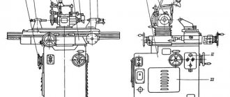
General layout of the sharpening machine 3E642. Description of the design of individual components
The machine is designed with longitudinal movement of the table (from a hydraulic cylinder and manually) on a fixed base, transverse (manual) and vertical (mechanized and manual) movements of the grinding headstock. The machine mechanisms are mounted inside and on the upper plane of the bed and carriage with a column.
A hydraulic station, a cooling unit, and a frequency drive are installed next to the machine.
bed
The bed (Fig. 8) is a box-shaped cast iron. The upper front part of the frame has processed plates for attaching the table base to them. On the upper part of the frame, a trough is cast on three sides to drain the coolant, which drains along the inclined bottom of the trough through an opening in the rear part of the frame into a cooling tank, which is installed at the rear wall of the frame.
Inside the frame there are two electronic niches that are closed with doors.
Table base
Body I (Fig. 9) of the table base is a cast iron casting of rectangular cross-section.
On both sides of the niche on the rear wall there are two axially movable gear wheels 7 with handwheels 6, which serve to carry out longitudinal movement of the table along the base guides.
To protect the table from vertical movements under lateral work loads, a clamp 14 is installed in the middle of the base body under the guides, consisting of a bearing 13 mounted on a horizontal axis that can be moved up and down.
On the front wall of the table base housing, through the control panel housing, mechanisms for transverse feeding and longitudinal movement of the table are installed in special holes.
A T-shaped groove is made on the upper horizontal surface of the trough 4 for collecting coolant and installing accessories. Trough 4 is attached to the back of the body I of the table base. Inside the body of the base of the table of the hydraulic machine there is a hydraulic cylinder 2 for longitudinal movement of the table, and in the body of the trough 4 there are hydraulic cylinders II for automatic shutdown of the handwheels 6 for manual movement of the table.
Remote control housing
The console body (Fig. 10) consists of body 1, which is attached to the side of the carriage with a column. Side consoles 2 are mounted on the inclined plane of the body.
Control Panel
The panel consists of a housing 1 (Fig. 11), on the front machine of which a cross-feed mechanism 4, a table movement mechanism 2 and a rigid stop 5 are installed in special holes. In the central niche there is a main control panel 3. A racing feed mechanism is installed in the upper part of the wall 7.
Carriage with column
The carriage with a column (Fig. 12) is designed for transverse and vertical movement of the grinding wheel. The carriage body I is installed on the frame guides 12 and moves along them using screw 2, which is attached together with the cross-feed mechanism on the front wall of the control panel housing. Nut 4 of the transverse movement screw 2 is installed motionless in the housing I of the carriage.
Using a spline connection and a conical pair 8, the transverse movement screw 2 is connected to a shaft 9, which runs in the rear part of the carriage in the transverse direction and carries redundant cross-feed flywheels 6 and II. This arrangement of controls ensures the possibility of cross-feeding from any workplace. The column is installed in the carriage hole perpendicular to the guides and is secured against rotation using special keys 10.
Column lifting mechanism
The lifting mechanism (Fig. 13) is a lead screw I with an internal gear 2 attached to it. Thanks to the kinematic connection of wheel 2 with the gear wheels of the grinding headstock and the lifting gearbox, the column moves in the vertical direction.
Lift reducer
The lifting gearbox (Fig. 14) is designed to lift and lower the column with the grinding headstock.
The lifting gearbox is a worm gearbox driven by an electric motor installed coaxially with worm I. The worm gear 2 is connected to the nut 3 of the column moving screw 4 so that when it rotates, the nut 3 moves the screw 4 in the axial direction, raising or lowering the column.
Cross feed mechanism
The cross-feed mechanism (Fig. 15) is designed to carry out coarse cross-feed of the grinding wheel.
The mechanism consists of a glass 5, in which a screw 7 is mounted with a helical gear 6 attached to it.
The mechanism is equipped with a rigid stop 4 installed in the dial 3. The fixation of the dial 3 with the rigid stop 4 is carried out using a screw 2. Transverse feed is carried out by rotating the flywheel I with the fine feed mechanism turned off. A splined shaft 8 is attached to screw 7, which serves to transmit rotation to screw 7 from duplicate cross-feed handwheels.
Fine feed mechanism
The mechanism (Fig. 16) carries out a fine transverse feed of the grinding wheel and consists of a worm I mounted in an eccentric sleeve 2. By turning this sleeve the mechanism is turned on or off. In this case, the worm I is inserted or disengaged from the helical gear 3. When the mechanism is turned on, the rotation of the cross-feed screw is carried out by the handwheel 4 sitting on the vertical shaft.
Grinding head
The grinding headstock (Fig. 17) consists of the housing 13 of the grinding head and the housing I of the column lifting shaft. The housing 13 of the grinding head has a hole for installing the grinding head and two grinding mutually perpendicular planes with T-shaped grooves. If necessary, various devices are installed on these planes.
Housing I contains a shaft 3 on rolling bearings and a conical gear pair 5,6, through which the column is moved manually by a handwheel 8 mounted on a horizontal rotary bracket 7.
Housing I of the lifting mechanism shaft is mounted on plate 10 with the ability to rotate 360°. In turn, the 10-nonet plate also rotates 360° on the column. The axis of the lifting mechanism shaft and the axis of the column are shifted by 55 mm, which makes it possible to increase the dimensions of the working space in the horizontal plane by 110 mm.
The housing 13 of the grinding head is installed with the possibility of reinstallation by 180°. The axis of the hole for the grinding head and the axis of rotation of the housing are shifted by 25 mm, and this makes it possible to increase the dimensions of the working space in the vertical plane by 50 mm.
The drive motor rotates together with the grinding head housing.
Grinding head
The grinding head (Fig. 18) consists of a spindle I installed in sleeve 2 on high-precision rolling bearings. In the front part of the spindle there is a conical hole for installing mandrels with grinding wheels. At the rear of the spindle there is an outer cone and a pulley 3 for driving the grinding head is installed. To tighten the mandrels, a cleaning rod 4 is installed inside.
Table
The table (Fig. 19) consists of two main parts: the table itself 2 and the working part I.
It is installed on the base 5 on roller guides 6 and moves in the longitudinal direction manually or from a hydraulic cylinder.
The working part of the table is rotary. The rotation angles are counted on two scales: with an accuracy of 1° (scale in the center) and up to 10′ (scale on the left). The rotary table is secured to the lower table using clamp I located in the middle of the rotary part and two clamps 3 located at the edges of the lower table 2.
Manual table movement mechanism
The table movement mechanism (Fig. 20) is used to manually move the table from the front of the machine. It consists of a shaft 2, at one end of which a flywheel 1 is attached, at the second - a gear wheel 3, which engages with the table rack through an intermediate gear.
Reverse mechanism
The reverse mechanism (Fig. 21) consists of two longitudinally movable stops I and 2, installed in the T-shaped groove of the table, and a switch block 3 located on the base of the table.
During manual work, the rigid stop located at the base of the table moves up and contacts on the table with stops I and 2, fixed to the amount of the required table travel.
When operating from a hydraulic cylinder, the rigid stop at the base of the table is recessed and the reverse occurs due to non-contact operation of the limit switches.
Set of mandrels
The set of mandrels (Fig. 23) is designed for fastening grinding wheels with a diameter of 200 to 50 mm of various profiles with mounting hole diameters of 32, 20, 16 and 13 mm. The machine can be used for processing with abrasive, diamond and CBN wheels. They are installed on a mandrel and secured by a flange 3 using a central screw I. The mandrel with a grinding wheel is installed in the conical hole of the spindle of the grinding head 4 and secured in it with a cleaning rod. Mandrels for circles with a diameter of more than 100 mm are equipped with balancing crackers 2.
Balancing of circles should be done on knives. To install the mandrel with the grinding wheel on the knives, use a balancing mandrel.
Cooling system
The cooling unit (Fig. 22) is installed at the rear of the machine.
The fittings are made in the form of a hose 2, which, using bracket I, can be secured to the base of the table or in another place convenient for work.
Set of casings
A set of casings is supplied with the machine (Fig. 24) for circles with a diameter of 150, 125 and 100 mm (PP, ChK, ChTs, T shape). The casing I is secured to the protruding part of the grinding head using a clamp 3, which has a radial groove with a rod 2 installed in it.
Technical characteristics of the sharpening machine 3E642E
The description of the technical characteristics of universal sharpening machines model 3E642E provides the following parameters: Main dimensions: - The largest diameter of the product installed in the center heads; — The greatest length of the product installed in the center headstocks; — The height of the centers above the working surface of the table; — The greatest distance from the axis of the grinding wheel to the line of centers in the vertical plane, taking into account the displacement of the axis of the grinding wheel by rotating the body of the grinding head; — Distance from the axis of the grinding wheel to the line of centers in the horizontal plane, taking into account the displacement of the grinding wheel in the horizontal plane; — Distance from the axis of the centers to the axis of the table groove in the horizontal plane; — Distance from the bottom of the machine base to the working surface of the table, etc.; The description of the technical characteristics of the table provides the following parameters: — Dimensions of the working surface; — T-slot width; — The greatest longitudinal movement; — Angle of rotation in the horizontal plane clockwise, counterclockwise and according to the precision rotation scale (with reinstallation of the key in the groove of the slider); — The price of dividing the rotation scales in the horizontal plane; — Speed limits for longitudinal movement (steplessly adjustable), etc.; The description of the technical characteristics of the grinding head contains the following parameters: - Vertical movement; — Transverse movement; — Angle of rotation of the spindle in the vertical plane; — Angle of rotation of the headstock in the horizontal plane; — Speed of vertical mechanical installation movement; — Limits of rotation speed of the grinding spindle; — with stepless regulation; — with step regulation; — End of the grinding spindle; — The largest diameter of the installed grinding wheel; — The magnitude of the vertical displacement of the grinding wheel axis by rotating the grinding head housing in the vertical plane by 160°; — The greatest displacement of the grinding wheel axis in the horizontal plane due to the eccentric plate; — Overall dimensions of the machine without attachments; — Total area of the machine with attached equipment; — Weight of the machine without attachments and accessories; The description of the technical characteristics of the universal headstock provides the following parameters: - The longest length of the product installed in the centers of the universal and tailstocks; — Angle of rotation in the horizontal plane, in the vertical plane; — Internal spindle cone; — Number of divisions when working with a dividing disk; In the description of the technical characteristics of the headstock, the internal cone of the quill is indicated; In the description of the technical characteristics of the right tailstock, the internal cone of the quill and the stroke of the quill, etc. are also indicated; The description of the technical characteristics of electrical equipment provides the following parameters: — Type of supply network current; - Current frequency; - Voltage; — Number of electric motors; — Grinding wheel drive electric motor (type, power, rotation speed); — Electric motor for vertical movement of the grinding head (type, power, rotation speed); — Hydraulic drive electric motor (type, rotation speed); — Electric motor of the product drive (type, power, rotation speed); — Total power of all electric motors; The description of the technical characteristics of the hydraulic equipment system and lubrication system provides the following parameters: — Hydraulic drive station (type, performance, oil grade); - Lubrication system; — Brand of lubricating oil; The description of the technical characteristics of the cooling system provides the following parameters: — Cooling pump (type, power, flow, pressure);
Adaptations
Universal headstock
The universal headstock (Fig. 27) is designed for sharpening the tail and attachment tools along the back and front surfaces located on the diameter or end, and is used as a front (drive) headstock for cylindrical and internal grinding, sharpening of cutters, etc.
The tool installed in the spindle of the universal headstock can be rotated in three mutually perpendicular planes at the required angles, measured respectively on scales 8 and 9 on the rotary body 11 and plate 10.
Sharpening of the tool can be done using a dividing disk or a stop. The dividing disk 3 with 24 grooves is installed on the pulley 2. The latch 6 is located on the rotary housing 4 and when dividing along the stop, it is removed from the groove.
The spindle is secured against rotation using button 5. Circular feeding of the product is carried out using button 7. The tool is secured in the spindle using a ramrod I.
Headstock
The headstock (Fig. 28) consists of a body 1 and a quill 2, which is secured with a handle 3.
Tailstock
The tailstock (Fig. 29) consists of a body 1, a bushing 2 with a Morse taper 2 for a replaceable center 3 and a handle 5 for retracting the center 3 when changing the product. The sleeve 2 is fixed with handle A. The center 3 is pushed out of the sleeve 2 by a pusher 6 with a button.
Universal prop
The universal stop (Fig. 30) is designed for the correct installation of the tooth of the sharpened tool with straight and helical teeth in relation to the grinding wheel (dividing along the existing teeth), as well as to ensure a constant position of the tool during the sharpening process.
When sharpening straight teeth along the rear edge, the angle is set by lowering the centered stop 2 by rotating head I with 20 divisions marked along the circumference. One revolution of the head corresponds to a vertical movement of the stop 2 by I, and a rotation by one division of the dial corresponds to a movement of 0.05 mm.
The rear angle is related to the amount of lowering of the stop from the center by the approximate dependence H = 0.085 D a, where D is the diameter on which the stop is installed, and is the rear angle.
The stop is installed on the table when sharpening spur tools and on the base of the table or on the grinding head when sharpening spiral teeth. A special holder 3 ensures fastening of the support 2 in various positions.
Performing various work with the thrust is ensured by the presence of three replaceable steel plates, different in size and configuration.
When sharpening a tool, when precise adjustment to the clearance angle is not required (grinding “by spark”), a rigid stop 4 can be used, which is simpler and more convenient.
Device for linear straightening of a wheel
The device (Fig. 31) is intended for linear dressing of the grinding wheel with a diamond pencil or diamond substitute. The device is installed on the machine table. Editing can be done either by the longitudinal stroke of the table or by the transverse stroke of the grinding headstock. Bracket 2 is rotatable and can be secured with screw 1 in any position.
Center Setting Tool
The device (Fig. 32) is used to align the stop or spindle axis of the grinding head to the height of the centers of the headstocks. The template can be mounted on a table or on the top surface of the grinding head.
To align the end of the grinding wheel with the axis of the centers of the center stocks (when sharpening the tool along the front edge), a center finder is used, which is installed in the hole of the tailstock or headstock quill. The end of the grinding wheel is brought to the stop against the cut part.
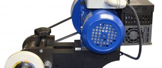
External cylindrical grinding attachment
The device (Fig. 33) is used to impart rotation to the product during cylindrical grinding. With its help, you can carry out cylindrical grinding of cylinders and conical surfaces in the centers or with fastening of products in the conical hole of the drive head spindle.
The device is mounted on a universal headstock 2; A bracket 4 with a pulley 7 and a tension device 8 is installed on the body 3 of the universal headstock. A plate 1 with a drive electric motor 6 is installed on the headstock bracket. The belt drive is covered by a casing 5. A casing 9 is used to enclose the driving device.
Accessories, replacement parts, tools included in the scope of delivery
- VZ-318M.92.010 – Casing (for circle Ø100 mm)
- VZ-318M.92.030 – Casing (for wheel Ø150 mm)
- 3E642E.P4.020 — Prop
- 3E642E.P4.010.19 — Prop
- 3E642E.91.015 — Mandrel (Ø 20 mm)
- 3E642E.91.016 — Mandrel (Ø 32 mm)
- VZ-318M.93.000 – Dust extraction
- VZ-318.P1 - Universal headstock
- VZ-318.P2 — Front headstock
- VZ-318.P3 — Rear headstock
- 3E642E.P4 — Universal prop
- VZ-318.P5 - Device for linear straightening of wheels and setting centers
- VZ-318M.90.203 — Center finder
- VZ-318M.90.204 – Center
Accessories, replacement parts, tools and accessories at additional cost
- VZ-318.P10 — Device for cylindrical sharpening of drills (mm)
- VZ-318.P11 — Vise with a tapered shank (jaw length 80 mm)
- VZ-318.P16 — Three-rotary vice (jaw length 100 mm)
- VZ-318.P17 — Device for external cylindrical grinding
- VZ-318.P28 — Device for sharpening in a spiral along the back surface (up to 63 mm)
- VZ-318.P41-02 — Collet chuck (mm collets)
- VZ-318.P53 - Device for sharpening cutting cutters (50 - 160 mm)
- VZ-318.P54 - Device for face grinding of circular saw teeth (200 - 400 mm)
- VZ-318.P55 — Device for sharpening carbide circular saws along tooth surfaces (200 - 500 mm)
- VZ-318.P56 - Device for sharpening circular saws along the end of the teeth (200 - 450 mm)
- VZ-318.P84 — Three-jaw chuck (100 mm)
- 3E642E.P7 — Podpuchnik
- 3E642E.P8 — Universal three-turn headstock
- 3E642E.P8.055 — Collet clamp
- 3E642E.P13 — Device for sharpening along the radius
- 3E642E.P19 — Device for sharpening countersinks and step drills (up to 50 mm)
- 3E642E.P22 — Device for sharpening according to a copier
- 3E642E.P23 — Device for sharpening helical cutters (up to 160 mm)
- 3E642E.P25 — Universal device for wheel dressing
- 3E642E.P28 — Device for sharpening tools in a spiral
- 3E642E.P30 — Rotary table (400 x 140 mm)
- 3E642E.P31 — Rear headstock with adjustable center height
- 3E642E.P32 — Set of backing plates
- 3E642E.P36 - Device for sharpening shaped cutters (50 - 100 mm)
- 3E642E.P37 — Three-rotary vice (jaw length 100 mm)
- 3E642E.P39 — Universal headstock with cone 7:24 (up to 250 mm)
- 3E642E.P50 - Device for sharpening cutters along a radius (80 - 400 mm)
- 3E642E.P51 — Device for backing taps (3 - 36 mm)
- 3E642E.P61 — Rear headstock with large reach
- 3E642E.P73 — Front headstock with large reach
- В19-101 — Vacuum cleaner (complete with hose L = 1.33 m; D = 0.075 m)
- VZ-318E.60.000 – Cooling
Universal sharpening machine 3E642E
The machine is designed for sharpening and finishing the main types of cutting tools made of tool steel, hard alloy and mineral ceramics with abrasive, diamond and CBN wheels. The machine can perform grinding work: cylindrical grinding (external and internal) and flat grinding.
Design features of the machine:
- — backlash-free table drive from the flywheel;
- — the grinding wheel motor is turned in the direction opposite to the spindle, which significantly expands technological capabilities and reduces changeover time;
- — small dimensions of the machine with large technological capabilities.
- — hydraulic drive for longitudinal movement of the table.
Basic technical data and characteristics of 3E642E
| Parameter | Meaning |
| Indicators of the workpiece processed on the machine | |
| The largest diameter of the product installed in the center headstocks, mm | 250* |
| Maximum length of the product installed in the center headstocks, mm | 630** |
| Maximum length of the processed surface, mm | 450 |
| * 330 mm using fixture 3E642E.P32 ** 1040 mm using fixtures 3E642E.P61 and 3E642E.P73 | |
| Indicators of the tool installed on the machine | |
| The largest diameters of the installed grinding wheel type 1 according to ISO 525-86 (GOST 2424-83), as well as CBN and diamond grinding wheels of similar shape and size, mm | 200 |
| other types, mm | 150 |
| Indicators of working and installation movements | |
| Maximum longitudinal movement of the table, mm | 450 |
| The largest angle of rotation of the table in the horizontal plane in the middle position, degrees. - clockwise - counterclockwise | 45 45 |
| The largest angle of rotation of the table in the horizontal plane according to the precision rotation scale, degrees. - clockwise - counterclockwise | 8 8 |
| Maximum vertical movement of the grinding head, mm | 250 |
| Maximum transverse movement of the grinding head, mm | 230 |
| Maximum displacement of the grinding wheel axis in the horizontal plane due to the eccentric plate, mm | 110 |
| The largest angle of rotation of the grinding head in the horizontal plane, degrees. | 360 |
| The largest angle of rotation of the grinding head in the vertical plane, degrees. - clockwise - counterclockwise | 40 20 |
| Indicators of the main and auxiliary movements of the machine | |
| Grinding spindle rotation speed limits, min-1 | 2200;3200;4400;6400 |
| Speed of vertical mechanized movement of the grinding head, mm/min | 390 |
| Indicators of the power characteristics of the machine | |
| Main drive drive power, kW | 1.1/1.5 |
| Total power of electric motors installed on the machine, kW | 3,18 |
| Other options | |
| Overall dimensions of the machine (together with separately located units and electrical equipment), mm - length - width - height (without lamp) | 1830 1940 1550 |
| Weight of the machine together with separately located units and electrical equipment), kg | 1320 |
| Processing roughness indicators (per batch) of sample products | |
| Grinding with the end of an abrasive wheel, microns | Ra ≤ 0.63 |
| Grinding with the end of a diamond wheel, microns | Ra ≤ 0.16 |
| Machine accuracy class | |
| Machine accuracy class according to GOST 8-82 | P |
Indicators of devices
Universal headstock VZ-318.P1
| Maximum length of the product installed in the centers of the universal and tailstocks, mm | 450 |
| Rotation angle, degrees. — in the horizontal plane — in the vertical plane | 360 240 |
| Inner spindle cone according to GOST 25557-82 | Morse 5AT6 |
| Number of divisions when working with a dividing disk | 3,4,6,8,12,24 |
Front headstock VZ-318.P2
| Internal cone of the quill according to GOST 25557-82 | Morse 2AT7 |
Rear headstock VZ-318.P3
| Internal cone of the quill according to GOST 25557-82 | Morse 2AT7 |
| Quill stroke, mm | 20 |
Universal support 3E642E.P4 (see previous figure)
| Movement of the thrust, mm - maximum - per one turn of the dial - per one division of the dial | 15 1.0 0.05 |
Device for linear straightening of wheels and installation of centers VZ-318.P5
| Center height, mm | 125 |
| Technical characteristics of electrical equipment | |
| Type of current | three-phase alternating |
| frequency Hz | 50 |
| Voltage, V | 380 |
| Number of electric motors on the machine | 2 |
| Main drive motor | |
| Type | AIR80V4/2 |
| power, kWt | 1,1/1,5 |
| Rotation speed, min-1 | 1500/3000 |
| Electric motor for vertical movement of the grinding head | |
| Type | AIR56V4 |
| power, kWt | 0.18 |
| Rotation speed, min-1 | 1500 |
| Hydraulic drive electric motor | 4AIR80A2 |
| power, kWt | 1,5 |
| Rotation speed, min-1 | 3500 |
| Lubrication system indicators | |
| Lubrication system | individual |
Delivery set (included in the price of the machine)
| Designation | Name | Col. | Note | |||
| 3E642E.00.000 | Complete machine | 1 | Cargo space dimensions, cm 1) LxBxH =»160x210x130 Gross 1550 kg. Net 1320 kg. | |||
| Included in the kit and the cost of the machine | ||||||
| 3E642E.72.040 | Hydro station | 1 | ||||
| Replacement Parts | ||||||
| VZ-318M.92.010 | Housing (for wheel Ø100 mm) | 1 | ||||
| VZ-318M.92.030 | Housing (for wheel Ø150 mm) | 1 | ||||
| 3E642E.P4.020 | Prop | 1 | ||||
| 3E642E.P4.010/19 | Prop | 1 | ||||
| Tools and accessories: | ||||||
| 3E642E.91.015 | Mandrel | 1 | Ø 20 mm. | |||
| 3E642E.91.016 | Mandrel | 1 | Ø 32mm. | |||
| VZ-318M.93.000 | Dust extraction | 1 | ||||
| Key D48-80 | 1 | |||||
| VZ-318.P1 | Universal headstock | 1 | ||||
| VZ-318.P2 | Headstock | 1 | ||||
| VZ-318.P3 | Tailstock | 1 | ||||
| 3E642E.P4 | Universal prop | 1 | ||||
| VZ-318.P5 | Device for linear straightening of wheels and setting centers | 1 | ||||
| VZ-318M.90.203 | Center finder | 1 | ||||
| VZ-318M.90.204 | Center | 1 | ||||
| Bolts GOST 13152 7002-2502 | 5 | |||||
| Nuts GOST 5927 М12-6Н.10.40Х.05 | 5 | |||||
| Washers GOST 11371 A12.05.05 | 5 | |||||
| Key 4VI60-01 | 1 | |||||
| Documentation | ||||||
| 3E642E.00.000 RE | Universal sharpening machine. Manual | 1 | ||||
| 3E642E.00.000 RE1 | Universal sharpening machine. Manual. Electrical equipment | 1 | ||||
| 3E642E.00.000 RE2 | Universal sharpening machine. Manual. Hydraulic equipment | |||||
| 3E642E.00.000 RE3 | Universal sharpening machine. Manual. Spare parts information | 1 | ||||
| 3E642E.71.000GZ | Hydraulic schematic diagram | 1 | ||||
| 3E642.80.000EZ | Electrical circuit diagram | 1 | ||||
| 3E642.80.000PEZ | List of elements | 1 | ||||
Replacement parts, tools and accessories that can be supplied at additional cost
| Designation | Name |
| VZ-318.P10 | Device for cylindrical sharpening of drills (Ø3 - 20 mm.) |
| VZ-318.P11 | Vise with tapered shank (jaw length 80 mm.) |
| VZ-318.P16 | Three-rotary vice (jaw length 100 mm.) |
| VZ-318.P17 | External cylindrical grinding attachment |
| VZ-318.P28 | Spiral sharpening device on the back surface (Ø up to 63 mm.) |
| VZ-318.P41-02 | Collet chuck (collets Ø 3 - 20 mm.) for VZ-318.P1 |
| VZ-318.P53 | Device for sharpening cutting cutters (Ø50-160 mm.) |
| VZ-318.P54 | Device for face grinding of circular saw teeth (Ø200-400 mm.) |
| VZ-318.P55 | Device for sharpening disc carbide saws on the front and rear surfaces of the teeth (Ø200-500 mm.) |
| VZ-318.P56 | Device for sharpening circular saws at the end of the teeth (Ø200-450 mm.) |
| VZ-318.P84 | Three-jaw chuck (Ø100 mm.) |
| 3E642E.P7 | Handyman |
| 3E642E.P8 | Universal three-turn headstock |
| 3E642E.P8.055 | Collet clamp for 3E642E.P8 |
| 3E642E.P13 | Radius sharpening device (radius up to 50 mm) |
| 3E642E.P19 | Device for sharpening countersinks and step drills (Ø up to 50 mm.) |
| 3E642E.P22 | Copier sharpening device |
| 3E642E.P23 | Device for sharpening helical cutters (Ø up to 160 mm.) |
| 3E642E.P25 | Universal device for wheel dressing |
| 3E642E.P28 | Device for sharpening tools in a spiral with a diameter of up to 160 mm.) |
| 3E642E.P30 | Rotary table (400x140 mm.) |
| 3E642E.P31 | Rear headstock with adjustable center height |
| 3E642E.P32 | Set of backing plates |
| 3E642E.P36 | Device for sharpening shaped cutters (Ø50-100 mm.) |
| 3E642E.P37 | Three-rotary vice (jaw length 100 mm.) |
| 3E642E.P39 | Universal headstock with cone 7:24 (Ø for cutters with a diameter of up to 250 mm.) |
| 3E642E.P50 | Device for sharpening cutters along the radius (Ø80-400 mm.) |
| 3E642E.P51 | Device for backing taps (Ø3-36 mm.) |
| 3E642E.P61 | Tailstock with long reach |
| 3E642E.P73 | Front headstock with long reach |
| B19-101 | Vacuum cleaner (complete with hose L=1.33m; D=0.075 m.) |
| VZ-318E.60.000 | Cooling |
| 3E642E.93A.000 | Fencing |
Electrical equipment of sharpening machine 3E642
Supply system
The power supply to the machine is carried out with a copper wire with a cross-section of 2.5 mm².
The supply wires are entered through a flange elbow with a G1/2″ thread.
The following AC and DC voltages are used on the machine:
- power circuit 3 variable 50 (60) Hz, 380 (220, 230, 400, 415, 440) V
- control circuit 3 variable 50 (60) Hz, 110 V
- alarm and local lighting circuit - alternating 50 (60) Hz, 24 V
Initial launch
Before starting up the machine, it is necessary to carry out an external inspection of the electrical equipment.
ATTENTION! During EXTERNAL INSPECTION, THE INPUT SWITCH SHOULD BE SET IN THE “OFF” POSITION.
During an external inspection of electrical equipment, it is necessary to check
- reliability of installation of electrical equipment and quality of electrical wiring;
- reliability of the grounding of the machine, as well as separate units and devices;
- condition and initial position of electrical equipment and mechanisms.
After inspection, disconnect by separating the connectors, and if they are missing, by disconnecting the power wires A6, B6, C6 (electric motor M6) of all electric motors at the terminal set in the electronic niche.
Set the QPI input switch to the “On” position. At the same time, the HLI signal lamp “Power connected” should light up on the control panel.
Using manual controls, check the precise operation of the magnetic starters.
When smooth operation of all electrical devices located on the control panel is achieved, connect the previously disconnected power wires of the M6 column drive electric motor to the terminals of the terminal block. Perform phasing of the network by correctly connecting the supply wires to the input terminal set, which is determined by the correspondence of the direction of movement of the column to the purpose of the push-button switches on the control panels that determined these movements. Next, connect the remaining electric motors.
Check the operation of electrical equipment in all modes without the product (idling).
Check the functionality of the emergency shutdown device (General Stop switch).
Check the operation of all locking devices according to section 5.
Check local lighting.
Description of work
Starting the grinding wheel, cooling pump (vacuum cleaner), and accessories is carried out by switches SB10, SB11, SB12, stopping by switches SB1, SB2, SB3 (“All stop”). The rotation direction and rotation speed of the grinding wheel are determined by switches SAI, SA2, respectively. The cooling pump (vacuum cleaner) can also be turned off autonomously using the SA3 switch. The choice of the direction of rotation and autonomous stop of devices P17, P51 can be carried out using switches SA4 and sA5, respectively.
Raising and lowering the column is carried out by switches SB4... SB6 and SB7... SB9, respectively.
Locks
The electrical circuit of the machine provides the following interlocks:
- impossibility of moving the column upward when the mechanism reaches the uppermost position - microswitch contact SQI (3.8);
- impossibility of moving the column down when the mechanism reaches its lowest position - microswitch contact SQ2 (3.9);
- inability to continue operation of the machine when switching switches SAI or SA2 or being in position “O” - contacts of switches SAI, SA2 (3.7).
Alarm system
The electrical circuit of the machine provides the following signaling: the “Power is connected” lamp is milky in color, located on the main console (HLI).
Protection
Protection against short circuit currents is carried out by an electromagnetic release of the QFI circuit breaker.
Overload protection is provided by thermal relays FPI... FP4, FP10 and fuses FUI, FU3, FU4. Zero protection is provided by the KMI magnetic starter.
The machine and separate units (hydraulic station, cooling unit, vacuum cleaner) are equipped with grounding clamps, which are connected to the workshop grounding circuit with conductors with a cross-section of 2.5 mm2.
Safety instructions
The safety of the machine's electrical equipment is ensured by following the instructions in this manual.
Design features of the 3E642 machine
- backlash-free table drive - from the flywheel;
- the grinding wheel motor is turned in the direction opposite to the spindle, which significantly expands technological capabilities and reduces changeover time;
- small dimensions of the machine with large technological capabilities;
- cast iron bed allows you to reduce vibrations when processing the part and increase the accuracy of processing;
- The dust extraction system increases the comfort of using the machine.
The mechanized raising and lowering of the grinding head improves working conditions and reduces auxiliary time.
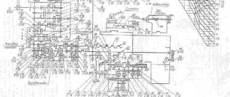
Electrical circuit diagram of the machine 3E642
Electrical diagram of sharpening machine 3e642
Electrical diagram of sharpening machine 3e642
Electrical diagram of sharpening machine 3e642
List of elements of the electrical circuit of the sharpening machine 3e642
Layout of electrical equipment on the 3e642 machine
Layout of electrical equipment on the 3e642 machine
Layout of electrical equipment on the 3e642 machine
Machine 3E642E. Universal sharpening. Manual. Hydraulic equipment
This instruction manual for the “Universal sharpening machine 3E642E” contains information necessary both for the maintenance personnel of this machine and for the employee directly involved in working on this machine. This manual is an electronic version in PDF format of the original paper version. This documentation contains the Manual (instructions) for operating the hydraulic equipment of the 3E642E universal sharpening machine.
CONTENT
Hydraulic circuit diagram Purpose of hydraulic equipment Design
- Hydrocommunication
- Hydropanel
Description of the hydraulic system Instructions for installation and operation
- Safety instructions
- Preparing the hydraulic system for start-up
Possible malfunctions and methods for eliminating them
download the operating manual for the hydraulic equipment of the 3E642E universal sharpening machine in good quality from the link below.
Technical data and characteristics of the 3E642 machine
| Parameter name | 3E642 | 3E642E |
| Main settings | ||
| Accuracy class according to GOST 8-82 | P | P |
| The largest dimensions of the processed products in the centers (length x diameter), mm | 630 x 250 | 630 x 250 |
| Height of centers above the desktop, mm | 125 | 125 |
| Machine work table | ||
| Dimensions of the working surface of the table according to GOST 6569-75 (length x width), mm | 900 x 140 | 900 x 140 |
| Maximum longitudinal movement of the table, mm | 450 | 450 |
| Table rotation angle in the horizontal plane, degrees | 0…45 | 0…45 |
| Speed of longitudinal movement of the table (steplessly adjustable), m/min | — | 0,2…12 |
| Grinding head | ||
| Maximum vertical movement of the headstock, mm | 235 | 235 |
| Price for dividing the feed dial for vertical movement of the table, mm | 0,005 | 0,005 |
| Maximum lateral movement of the headstock, mm | 230 | 230 |
| Price for dividing the lateral movement feed dial, mm | 0,001 | 0,001 |
| Headstock rotation angle in the horizontal plane, degrees | 360 | 360 |
| Grinding head | ||
| Grinding wheel speed with stepless control, rpm | — | 2200…6400 |
| Grinding wheel speed with stepwise regulation, rpm | 2200,3200, 4400,6400 | 2200,3200, 4400,6400 |
| The end of the grinding spindle according to GOST 2324-77 version 2 | Morse 4 | Morse 4 |
| The largest diameter of the installed grinding wheel according to GOST 2424-83 type PP, mm | 200 | 200 |
| The largest diameter of the installed grinding wheel according to GOST 2424-83 of other types, mm | 150 | 150 |
| Electrical equipment and machine drive | ||
| Number of electric motors on the machine | 4 | 5 |
| Spindle drive electric motor, kW (rpm) | 2,2 (3000) | 2,2 (3000) |
| Electric motor for vertical movement of the grinding head, kW (rpm) | 0,18(1500) | 0,18(1500) |
| Electric motor for vertical movement of the grinding head, kW (rpm) | 0,18 (1500) | 0,18 (1500) |
| Product drive electric motor, kW (rpm) | 0,25 (1500) | 0,25(1500) |
| Hydraulic drive electric motor, kW (rpm) | — | 1,1 (1000) |
| Hydraulic drive pump capacity, l/min | — | 10 |
| Cooling pump electric motor, kW (rpm) | 0,12 (2800) | 0,12 (2800) |
| Cooling pump capacity, l/min | 22 | 22 |
| Total installed power of all electric motors with stepless/stepless regulation, kW | 1,93 /- | 3,03 /3,73 |
| type of supply current | 50Hz, 380/220V | 50Hz, 380/220V |
| Dimensions and weight of the machine | ||
| Machine dimensions, mm | 1745 x 1940 x 1550 | 1830 x 1940 x 1550 |
| Machine weight, kg | 1160 | 1200 |
- Universal sharpening machines 3E642E, 3E642. Operating manual 3E642E00.00.000 RE, 1990
- Dibner L.G., Tsofin E.E. Sharpening machines and semi-automatic machines, 1978
- Demyanovsky K.I., Dunaev V.D. Sharpening wood cutting tools, 1965
- Kudryashov A.A. Tool production machines, 1968
- Lisova A.I. Design, adjustment and operation of metal-cutting machines, 1971
- Menitsky I.D. Universal sharpening machines, 1968
- Paley M. M. Technology of production of metal-cutting tools, 1982
- Rozhkov D.S. Design, setup and operation of equipment for sharpening wood-cutting tools, 1978
Bibliography:
Related Links. Additional Information
- Classification and main characteristics of the grinding group
- Repair, restoration and modernization of grinding machines: the American approach
- Cylindrical grinding. Processing on cylindrical grinding machines. Grinding Methods
- Setting up a cylindrical grinding machine when installing parts in centers
- CNC grinding machines
- Marking of grinding wheels
- Testing and checking metal-cutting machines for accuracy
- Grinding machines. Market of grinding machines in Russia
- Directory of grinding machine manufacturers
- Directory of factories producing metal-cutting machines
- Directory of surface grinding machines
Home About the company News Articles Price list Contacts Reference information Interesting video KPO woodworking machines Manufacturers
3E642. Universal sharpening machine. Specifications
Technical characteristics of machines are the main indicator of the suitability of a machine for performing certain jobs on machines. For sharpening machines, the main characteristics are:
- largest diameter D of the workpiece (part) being processed
- maximum length L of the workpiece (part) being processed
- Circle speed m/sec
Below is a table with the technical characteristics of the 3E642 universal sharpening machine. More detailed technical characteristics of the machine can be found in the passport of the machine 3E642
| Quantities | ||
| Maximum workpiece diameter | mm | 250 |
| Maximum product length | mm | 630 |
| Height of centers above the working surface of the table | mm | 125 |
| Dimensions of the working surface of the table (LxW) | mm | 900x140 |
| Dimensions of the machine, without attachments (LxWxH) | mm | 1745x1940x1550 |
| Machine weight, without attachments | kg | 1160 |
Attention! The technical specifications given in the above table are for reference only. Machines produced by different manufacturers and in different years may have characteristics that differ from those given in the table.