Winding a toroidal transformer with your own hands
Winding a transformer with your own hands is not a difficult task if you prepare for it in advance. People who make various radio equipment or power tools have a need for transformers for specific needs. Since it is not always possible to purchase certain products, craftsmen often wind toroidal transformers themselves. Those who try to wind the winding for the first time encounter difficulties: they cannot determine the correctness of the calculations or select the appropriate parts and technology. It is important to understand that different types are wound differently.
- Preparing for winding
- Necessary materials
- How to speed up your workflow
Toroidal devices are also . The calculation of a toroidal transformer and its winding will be special. Since radio amateurs and craftsmen create parts for power equipment, but do not always have sufficient knowledge and experience to manufacture them, this material will help this category of people understand the nuances.
What is a transformer winding machine?
For experienced electricians and radio amateurs, when working with their own hands, they will definitely need a machine for winding transformers.
Household appliances have in their design a lot of all kinds of coils and transformers (including toroidal ones), which over time become unusable and need to be repaired. Transformer winding machine
In addition, many craftsmen would not mind having a homemade manual or electric coil winding machine in their arsenal of tools, as it can significantly reduce time and improve the quality of winding.
Design and operating principle
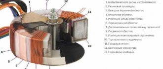
The design feature of such a transformer lies in the shape of the magnetic circuit, which represents a closed ring, called a torus.
Otherwise, the composition of its elements is identical to other types of electrical machines:
- Winding - made with a copper conductor, divided into primary and secondary. Both windings may differ in conductor cross-section.
- Toroidal core - has the shape of a ring, is made by typesetting, strip steel or monolithic iron, depending on the dimensions and purpose. The material used is ferromagnetic alloys, which provide good magnetic conductivity.
- Insulating materials - part of the dielectric is pre-applied to the installation wires, the rest of the dielectric is separated by the torus coil with the iron, the windings among themselves, between the coils and the casing. Tape or varnished fabric materials, electrical insulating cardboard, glue, etc. are used as insulation.
- Protective casing - designed both to protect the power transformer from mechanical damage and to prevent human contact with the surface of the windings.
- Conclusions of the secondary and network windings , fasteners and auxiliary parts.
Rice.
1. Design of a toroidal transformer The principle of operation of a toroidal transformer is to supply voltage to the terminals of the primary winding. After which an electric current begins to flow in it, which creates a magnetic flux inside the turns. The magnetic flux moves inside the coil frames and induces an emf in the secondary winding. If a load is connected to its terminals, the specified power will be consumed.
This device has found application in toroidal autotransformers (LATRs), radio electronics, welding transformers and other converters. At home, they rewind this type of transformer through a relatively simple process.
Manufacturing of toroidal coils
Radio amateurs quite widely use inductors with toroidal (ring) magnetic cores in their designs. Compared to coils with magnetic cores of other types, such coils have a number of advantages - high quality factor, absence of external stray fields, immunity to external magnetic fields, etc.
However, winding coils on toroidal magnetic cores is associated with certain difficulties, especially with a large number of turns. When winding such coils, radio amateurs usually use homemade flat spools or shuttles. To facilitate the manufacture of coils containing a large number of turns, sometimes the ring magnetic core (usually ferrite) is carefully broken into two parts, half the number of turns is wound on each of them, after which the halves of the magnetic core are glued together, and the half-windings are connected in series (i.e. the end of one with the beginning of the other). This method has significant disadvantages: due to mechanical influences, the initial magnetic permeability of the magnetic core material is significantly reduced, the presence of non-magnetic gaps in the gluing areas reduces the magnetic permeability - as a result, the effective magnetic permeability of the magnetic core is reduced by an order of magnitude, or even more. To obtain the required inductance of the coil, it is necessary to proportionally increase the number of its turns, as a result of which the active resistance of the winding increases and its quality factor decreases. Due to the uneven distribution of the coil turns along the magnetic core, the magnetic field is no longer localized inside the coil; additional bulging of the magnetic field from the magnetic core occurs at the gluing points - external stray fields increase, the coil requires shielding.
The proposed method makes it possible to produce inductors on toroidal (ring) magnetic cores with an outer diameter of 10 mm or less, inductance up to several henries, with low labor costs. Using this method, it is possible to produce coils with the maximum achievable values of inductance and quality factor, completely filling the magnetic circuit window with the winding.
This result can be achieved if the coil is wound with a high-frequency winding wire (outdated name - Litz wire), which is a bundle (bundle) of wires with a diameter of 0.03-0.1 mm insulated from one another and twisted together with an outer fibrous single-layer silk (LESHO brand) or lavsan (LELO brand) insulation (if the external insulation consists of two layers - LESHD or LE/1D, respectively). The wires in a bundle can be from three to several hundred, but for this purpose the most suitable are wires with the number of wires 7-10 with a diameter of 0.05 or 0.07 mm, for example, LESHO or LELO 10×0.05; 7×0.07; 10×0.07.
The essence of the method is that the coil is wound with a relatively thick wire harness, and then the thin insulated wires that make it up are connected to each other in a consistent manner, as a result of which the required number of turns is reduced by a factor equal to the number of wires. The technological process consists of three operations performed sequentially: preparing the magnetic circuit, actually winding and connecting the wires.
Preparing the magnetic circuit involves carefully rounding the sharp edges with fine-grained sandpaper to avoid damage to the insulation of the thin winding wire. After this, the magnetic circuit is wrapped with a slight tension with fluoroplastic tape. This tape called FUM (fluoroplastic sealing material) is sold in hardware stores. It must be dissolved into strips 4...5 mm wide and wrapped around the magnetic circuit in one layer with such a strip. This achieves two goals: inter-turn short circuits of the coil winding through the magnetic core are eliminated and the friction of the wire against it during winding is reduced. When working with ferrite magnetic cores, you should avoid direct impacts on them and their falling onto hard objects, since this can cause a significant irreversible change in the initial magnetic permeability of the material.
Next, determine the required length of stranded wire for the winding. If the number of turns of the coil is known, then the number of turns of the wire is calculated by dividing the first of these numbers by the number of wires in the wire. By multiplying the number of turns by the average length of the turn, we obtain the required wire length. I calculate the average coil length l using the empirical formula l = D +3h, where D is the outer diameter of the magnetic core; h is its height. For a ferrite ring of standard size K10x6x5 (from the CFL electronic ballast choke) l = 25 mm. For a coil consisting of 150 turns (window fill factor less than 0.5), approximately 25x150 = 3750 mm ≈ 3.8 m of LESHO 7x0.07 wire will be required. This will make it possible to obtain a coil containing 900... 1000 turns of wire with a diameter of 0.07 mm and an inductance of over 1 H.
Next, having threaded the wire through the magnetic core and placing the latter approximately in the middle of the wire, I tie it with a single knot so that the crossing point of wire 1 is located on the outer cylindrical surface of ring 2 ( Fig. 1 ). The ends of the wire are approximately 50 mm long and the knot is coated with nitro glue. About five minutes later, after the glue has dried, I begin to wind the coil, tightly laying the turns along the inner diameter of the ring. To avoid spreading of the turns, every two or three turns I “repeat” the knot, passing the end of the wire inside the turn. Having gone through the first layer and securing the end of the wire with a knot, I use a wooden toothpick to eliminate the barrel-like shape of the winding inside the ring, pressing the wire towards the magnetic core. I wind the next layer with the second end of the wire with a slight tension so as not to break the wire. The rigid, glue-impregnated ends of the wire make it easier to insert it into the ring. So, alternating winding with one and the other end of the wire, I fill the window, evenly distributing the winding around the ring. After winding the coil, I make a frame.
Rice. 1
To do this, in a plate made of sheet polystyrene or other thermoplastic material 3...4 mm thick, I drill a hole with a diameter 2...3 mm less than the diameter of the resulting coil. Then I insert the rod of a heated soldering iron with a power of 40...65 W into it and use its side surface, cleaned of scale, to heat the walls of the hole. I heat it up by continuously moving the soldering iron rod along the cylindrical surface of the hole. At the same time, it seems to “flare out”, its diameter increases and annular beads appear on its edges. Having flared the hole to the required diameter, I insert the coil into it, and while the workpiece is still warm, I carefully press the beads around the coil with tweezers. As a result, after the workpiece has cooled, it is securely fixed in the hole. Next, I file the workpiece until the required frame shape is obtained ( Fig. 2 ). I cut off the excess wire, leaving the ends 25...30 mm long. Having separated one wire from each bundle, I tinned them using a well-known method - carefully pulling the wire under the tip of a soldering iron with collected solder along a piece of polyvinyl chloride insulation removed from the mounting wire. In this case, the wire insulation is destroyed and it is tinned. I fuse pieces of tinned wire with a diameter of 0.6...0.8 mm into the ends of frame 3 - they will serve as terminals 1 of coil 2. I wind the tinned wires onto terminals 1, and solder the winding points.
Rice. 2
Tinning a thin wire is a very delicate operation, there is a high risk of breaking it, so I connect the remaining wires without removing the insulation by welding. To do this, take one wire from the beginning and end of the winding, twist them to a length of about 10 mm and heat the twisted area in the flame of a reusable gas lighter with an injection torch. The flame of such a lighter looks like a narrow blue cone. When heated, the wires melt, forming a ball of molten metal 4 at the junction. After cooling, I place the junction on the frame so that the wires are adjacent to the frame 3, and fix it on it, heating it with the tip of a sharpened soldering iron until the ball and wires are immersed in the body of the frame. This ensures mechanical strength of the joint. After this, I twist, weld and fix the second pair of wires in the frame, then the third, etc. As a result, all the wires are connected in series, so there is no need to “test” them. Having connected all the wires, I make sure that the winding is intact and that there are no short-circuited turns in the resulting inductor, after which I cover the wire connections with BF-2 glue.
The proposed method for manufacturing inductors can significantly reduce labor costs in their manufacture. It should, however, be taken into account that the own capacity of a coil wound in this way is much greater than that of a coil wound using conventional technology.
Author: K. MOROZ, Belebey, Bashkortostan
Unwinding wire
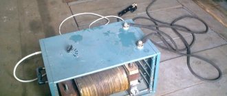
If you plan to use an old transformer as a source of wire for winding, then you can make the work easier and faster with the help of a small unwinding machine. Its use allows you to remove the wire evenly, avoiding jerks and damage to the insulation. The operating principle and structure of the device resemble a winding machine, but the coil moves in the opposite direction.
Quite simple to make and use, the device looks almost the same as a manual machine. The difference lies in the absence of a handle and the presence of a device for fixing the hollow transformer body on a metal axis. Secure the body using a piece of cardboard, paper or any other suitable material rolled into a multilayer tube. Thus, it will be possible to ensure smooth unwinding, no jumps and no impacts of the coil on the axis.
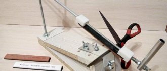
Figure 5. Machine with pins.
By slightly complicating the design and adding clamps made of wooden, metal or textolite plates, you can make the device much more convenient to use. Instead of a metal axle, in this case, use a threaded pin with a diameter of 6 mm. It will not just rotate freely in the racks, but will be fixed by a system of wing nuts (Fig. 5).
When unwinding high-power transformers, insulating material can be found between the primary and secondary windings. You should not throw it away, as it is highly reliable and will be useful when designing your device. In addition, when disassembling an old transformer, you will encounter such a problem as individual layers of wire coated with a transparent material - a special varnish. There is no need to try to remove or scrape it off, as the thin outer coil of wire can easily be damaged in the process. It is best to unwind such a transformer on a machine, making smooth and slow movements, while the wire itself will come off normally.
Two pulleys are connected by a belt drive
The axles in the winding machine are connected to each other by a system of pulleys of different radii. The pulleys attached to the axles rotate using a belt drive. A belt is used as a belt.
To calculate the pulleys according to the diameter of the winding wire, we accept the following conditions and derive the formula:
— The stacker axis pulley is 100mm;
— A pulley on an axis with a fixed coil (winder) is equal to the thickness of the required wire, multiplied by 100.
For example, for 0.1 mm wire, we use a 10 mm pulley on the axis of the winder. For a diameter of 0.25 wire, a 25 mm pulley.
If possible, it is better to make pulleys with a pitch of 1 mm and select them during the winding process using this formula
The error depends on the accuracy of the diameter of the manufactured pulleys and the tension of the belt. If you use a stepper motor with a gear transmission as a drive in the design instead of a belt and precisely cut pulleys, then the error can be brought closer to zero.
Now I’ll tell you how to make a pulley with your own hands at home without turning to a turner. My set of pulleys is made of the same material as the bed of the winding machine. Using a compass, I marked out the required diameters of the pulleys and added a few millimeters on the larger side to machine the groove for the belt to the required size. Holes were drilled along the contour of the markings with a screwdriver and partitions were cut between them. So I collected the required number of blanks for the pulleys. I used an unnecessary “Assistant” meat grinder as a lathe.
I don’t remember exactly, I cut a thread on the meat grinder motor shaft, or it turned out to be suitable, but a pin was screwed through a long bushing nut. A blank with a slightly larger diameter than the required pulley was screwed onto the stud through nuts and washers. The meat grinder was turned on and all the irregularities were rounded to a round shape with a metal hacksaw/file, and a groove (groove) for the belt was machined with a needle file. During the process, the diameters of the homemade pulleys were periodically checked with calipers.
Self-production
The price of finished products is high, and it is not always possible to find a device with the required parameters. Therefore, it is advisable to make a transformer or autotransformer with your own hands. In addition to making a transformer from scratch, it is possible to rewind a faulty device.
To manufacture the product you will need transformer hardware and wire. Iron consists of plates assembled in the form of a torus and forming a magnetic circuit. You can buy it or take it from old disassembled devices. For example, take plates from industrial transformers and, using a device in the form of a cut ring, roll the metal into donut-shaped plates. Assemble the plates, cover the core with fiberglass and fill it with varnish.
The turns of the windings are made of copper wire of the required diameter. The winding itself is not difficult:
- The primary winding is wound. To do this, one end of the wire is fixed at a distance of about three centimeters from the surface of the iron, and the remaining part of the wire is rolled up in the form of a strip.
- A strip of wire is threaded one by one through the inner hole of the core, wrapping its edges, and is evenly distributed over the entire surface. At the end, the output is fixed and output near the beginning of the winding at the same distance as the beginning.
- The primary winding is covered with a layer of dielectric (fiberglass) on top.
- The secondary winding is wound in the same way.
- After completing the required number of turns, fiberglass is wound on top, and the transformer is varnished.
Components of a winding machine and its operating principle
The elements of the winding machine were assembled slowly. Almost everything was taken from old Soviet film equipment. Moving parts: handle, axle studs, guide roller - everything is equipped with bearings. Studs, nuts, washers and angles were purchased at a hardware store. I only had to spend money on studs, long nuts and angles. Otherwise, everything is made from available materials.
To accurately select the wire winding density, a set of several pulleys is threaded onto the stacker pin. So, in the case of loose winding, it was possible to move the belt one size and adjust the speed of rotation of the axes. During the process of winding the wire, the belt is twisted depending on the direction of the winding stroke according to the figure-of-eight shape or the direct position of the belt. You should make a couple of dozen test turns to correctly adjust the pulleys to the diameter of the wire.
A base is made from wood or other material in the shape of the inside of the transformer coil and is fixed to the stud with wing nuts. You can also make universal holding corners to secure the coil. A demonstration of the operation of the winding machine is shown in the video:
[Here will be a video of the transformer winding process]
Principle of operation
The simplest toroidal transformer consists of two windings on a ring and a steel core. The primary winding is connected to a source of electric current, and the secondary winding is connected to a consumer of electricity. Due to the magnetic circuit, the individual windings are connected to each other and their inductive coupling is strengthened. When the power is turned on, an alternating magnetic flux is created in the primary winding. Meshing with individual windings, this flux creates an electromagnetic force in them, which depends on the number of turns of the winding. If you change the number of windings, you can make a transformer to convert any voltage.
Photo - Operating principle
Also, converters of this type are either buck or boost. A toroidal step-down transformer has a high voltage on the secondary winding terminals and a low voltage on the primary winding. Increasing is the opposite. In addition, the windings can be of higher or lower voltage, depending on the characteristics of the network.
Necessary materials
Winding materials require careful selection ; each detail is important. In particular, you will need:
- Transformer frame. It is used to insulate the core from the windings and also holds the winding coils. It is made from strong and thin dielectric materials so as not to take up too much space in the intervals (“windows”) of the core. You can use cardboard, microfiber, textolite. The thickness of the material should not be more than 2 mm. The frame is glued together using ordinary carpentry glue (nitro glue). Its shape and dimensions depend entirely on the core, its height is slightly greater than that of the plate (winding height).
- Core. This role is usually performed by magnetic circuits. The best solution would be to use plates from disassembled transformers, since they are made from suitable alloys and are designed for a certain number of turns. Magnetic cores have a variety of shapes, but most often there are products in the form of the letter “W”. In addition, they can be cut from various blanks that are available. To determine the exact dimensions, the wires of the windings are pre-wound.
- Wires. Here you need to use two types: for winding and for leads. The optimal solution for transforming devices is copper wires with enamel insulation (PEL or PE type). They are enough even for power transformers. A wide selection of sections allows you to choose the most suitable option. PV wires are also often used. For the output, it is best to take wires with multi-colored insulation so as not to get confused when connecting.
- Insulation pads. Helps increase the insulation of the winding wire. As a rule, thin and thick paper is used (tracing paper is perfect), which should be laid between the rows. But the paper must be intact, there should be no tears or punctures, even the most insignificant ones.
Calculation method - step-by-step instructions
The calculation of the toroidal transformer itself is divided into two parts:
- You can directly calculate the power of a toroidal core in order to determine it; if you have a specific core, or a given power, then determine the dimensions of the future transformer.
- Calculation of the electrical part itself, which includes the number of turns in the windings, as well as what cross-section will be used in the windings and wire material.
Core calculation
We will produce it using a formula that already includes constants to simplify the understanding of its results. Next, all that remains is to substitute only variable values into the formula below, namely:
“P=1.9*Sc*So” , where:
- P is the power that can be obtained using a core with such overall dimensions
- 1.9 – the result of mathematical operations on all constants for this type of transformers
- Sc - core area, unit of measurement square centimeters
- So is the area of the hole in the core body, in “sq. cm."
If the transformer made will have the main purpose of welding, then the dimensions of its core must be adequate, otherwise the resulting power of the device will not be enough to perform its functions. For example, take the following values and use a calculator to calculate. "P=1.9*70*70=9310 Watt"
Let's determine the number of turns of the primary winding
First of all, we will consider the calculation with a single primary winding, without adjustment. To do this, we first find out how many winding turns a toroidal transformer must have to produce 1 volt of voltage. Let's apply the following formula. K=35/Sc , where:
- K – number of turns per 1 volt of voltage.
- 35 is a constant that is the same for all types of toroidal cores.
- Sc is the area of the core, the unit of measurement is square centimeters.
Thus, if we have a core with an area of 70 "sq. see", then substituting the values in the formula, we get the following situation. “K=35/70=0.5” turns for each volt, and accordingly we find out the volume of the primary winding by applying the appropriate formula. “W1=U1*K” , where:
- W1 is the number of turns in the first winding.
- U1 is the required voltage at this point.
- K – number of turns per 1 volt of voltage.
“W1=220*0.5=110” – turns. Taking into account the fact that we are carrying out calculations for a welding transformer, we will take the operating voltage of the secondary equal to 35 volts, then based on a similar formula, we will obtain. “W2=35*0.5=17.5” – turns.
Calculation of the cross-section of the wires used
To calculate the required cross-sections, you need to understand what current will flow through them, this is the only parameter that affects the thickness of the material used, so, calculating the amount of current in the transformer windings: “I AC = 9310 Watts/220 Volts = 42.3 Amperes” With a secondary winding several more complicated, everything must rely on the arc voltage and welding current. “I weld.=(29 Volt-14)/0.05=300 Ampere” , where 29 volts is the average value of the welding arc. Now we check whether such power is possible for our device: 300 Amperes * 29 Volts = 8700 Watts.
Current transformer
In addition to the standard type of voltage transformers, there is a special type called a current transformer. Its main purpose is to change the current value relative to its input. Another name for this type of device is current.
A current transformer is a measuring device designed to measure the strength of alternating current. Current devices are used when it is necessary to measure high current or to protect semiconductor devices from abnormal values that occur on the line.
The current device is no different in appearance from a voltage transformer; its differences are in the connection and the number of turns in the winding. The primary is made using one or a pair of turns. These turns are passed through a toroidal magnetic circuit, and it is through them that the current is measured. Current devices are made not only of the toroidal type, but can also be made on other types of cores. The main condition is that the wire being measured makes a full turn.
With this design, the secondary winding is shunted with a low-resistance resistance. In this case, the voltage on this winding should not be large, since during the passage of the highest currents the core will be in saturation mode.
In some cases, measurements are carried out on several conductors that are passed through the torus. Then the magnitude of the current will be proportional to the strength of the sum of the currents.
Transformer Winding Tools
First of all, you should think about making your work easier with the help of various devices. In the factory production of transformers, they are made, of course, using special machines, and not by hand.
It hardly makes sense for an amateur to think about a machine, but simple devices to make work easier will certainly pay off.
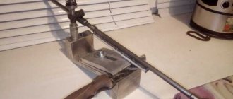
The simplest option is two posts attached to a wooden board, and a metal rod between them, curved on one side in the shape of a handle. Externally, it looks like a spit. The rod is threaded through the holes in the racks, usually no more than 1 cm thick. The axis of the “skewer” must be threaded through the frame of the future transformer (we do not stop at its manufacture, since its type and features depend on the intended function of the device). Typically, a wooden block with a hole for the axle and a size suitable for the frame is used for this.
Diagram of a machine for winding transformers.
If you have a hand drill, the task becomes easier. The drill is securely attached parallel to the table (you can simply clamp it in a vice) so that its handle can rotate freely. A metal rod is inserted into the drill chuck with a block mounted on it, on which the transformer frame is fixed. Ideally, the rod should be threaded, then the block can be easily fixed by simply clamping it on both sides with nuts. In some cases, it is possible to do without a block altogether, clamping the frame either with the nuts themselves, or with wooden planks or textolite plates.
You can use a telephone inductor, a machine for textile bobbins, a device for rewinding film and other similar mechanisms as a winding mechanism. The key point is the “soft”, without jerks, progress of the process.
In addition, you will also need an unwinding device (especially if you are using an old transformer as a wire source). Its stroke should also be uniform, so as not to complicate the process of winding a new transformer, and also not to damage the wire insulation. Typically, the unwinding device is made in a similar way to the winding device, but a handle for rotation is optional.
An additional device for counting the number of turns may also be useful. You can get by with an oral count, when each turn (or a couple of turns) is counted, and every hundred is marked on paper. If you use a machine with a gear drive, you should not forget about the gear ratio.
However, you can use some kind of device. A water meter, an electric meter, and a bicycle speedometer are suitable. The meter is connected to the winding machine using a flexible roller (a rubber tube with fairly thick walls) or gears.
How to speed up your workflow
Many radio amateurs have in their arsenal simple special units with which winding is made. In many cases, we are talking about simple structures in the form of a small table or table stand, on which several bars with a rotating longitudinal axis are installed. The length of the axis itself must exceed the length of the winding frame by 2 times. A handle is attached to one of the exits from the bars, allowing you to rotate the device.
Reel frames are placed on the axle , which are locked on both sides with limiting pins (they prevent the frame from moving along the axis).