Slope and Taper - Definition, designation on the drawing, formula for calculating slope and taper
Sometimes, in tasks on descriptive geometry or work on engineering graphics, or when performing other drawings, it is necessary to construct a slope and a cone. In this article you will learn about what slope and taper are, how to build them, and how to correctly indicate them in the drawing. Slope. Slope is the deviation of a straight line from a vertical or horizontal position. Definition of slope. The slope is defined as the ratio of the opposite side of the angle of a right triangle to the adjacent side, that is, it is expressed by the tangent of the angle a. The slope can be calculated using the formula i=AC/AB=tga.
Features of constructing slope and taper
The field of drawing has developed over a fairly long period. It has been used many centuries ago to transfer accumulated knowledge and skills. Today, the manufacture of all products can be carried out exclusively using drawings. At the same time, it receives the most attention when setting up mass production. Over a long period of development of drawing, standards have been developed that can significantly increase the readability of all information. An example is GOST 8593-81. It largely characterizes the taper and slope and the methods used to display them. Descriptive geometry is used to study modern science, as well as to create various techniques. In addition, a variety of correspondence tables have been developed that can be used when carrying out direct calculations.
Various concepts such as fillet, slope and taper are displayed in a specific way. This takes into account the scope of application of the technical documentation being developed and many other points.
The features of constructing an angle and taper include the following points:
- The main lines are displayed in a bolder style, except when there is a thread on the surface.
- When carrying out work, a variety of tools can be used. It all depends on which construction method is used in a particular case. An example is a right triangle, with the help of which a right angle or a protractor is maintained.
- The display of the main dimensions is carried out depending on the features of the drawing. Most often, a basic value is indicated, with the help of which others are determined. Today, the method of direct sizing, when it is necessary to measure lines and angles using appropriate tools taking into account the scale, is practically not used. This is due to the difficulties that arise on the production line.
In general, we can say that the basic standards are taken into account by the specialist when directly carrying out the work of constructing the drawing.
Designation of taper in the drawing
When creating technical documentation, all established standards must be taken into account, otherwise it cannot be used in the future. When considering the taper designation in the drawings, attention should be paid to the following points:
- The diameter of the large base is displayed. The figure under consideration is formed by a body of rotation, which is characterized by a diametrical indicator. In the case of a cone, there may be several of them, and the change in the indicator occurs smoothly, not stepwise. As a rule, such a figure has a larger diameter, as well as an intermediate one if there is a step.
- The diameter of the smaller base is applied. The smaller base is responsible for forming the required angle.
- The length of the cone is calculated. The distance between the smaller and larger bases is an indicator of length.
- Based on the constructed image, the angle is determined. As a rule, appropriate calculations are carried out for this. In the case of determining the size from a printed image, using a special measuring device, the accuracy is significantly reduced. The second method is used when creating a drawing for the production of non-critical parts.
The simplest designation of taper also provides for displaying additional dimensions, for example, reference. In some cases, a taper sign is used, which makes it immediately clear about the difference in diameters.
There are quite a large number of different standards that relate to the designation of taper. The features include the following:
- The angle can be specified in degrees as a fraction or as a percentage. The choice is made depending on the area of application of the drawing. An example is that in the mechanical engineering field the value of a degree is indicated.
- In the mechanical engineering field, the concept of normal taper is included in a special group. It varies within a certain range and can be 30, 45, 60, 75, 90, 120°. Similar indicators are characteristic of most products that are used in the assembly of various mechanisms. At the same time, it is much easier to maintain such values when using turning equipment. However, if necessary, inaccurate angles can be maintained, it all depends on the specific case.
- When drawing the main dimensions, a drawing font is used. It is characterized by quite a large number of features that must be taken into account. Tabular information is used for correct display.
- To begin with, the taper icon is indicated from which the arrow is drawn and the value is displayed. The display features largely depend on what kind of drawing. In some cases, a large number of different sizes are applied, making taper application much more difficult. That is why it is possible to use several different methods for displaying such information.
In the drawing, the indicator in question is indicated in the form of a triangle. This requires a digital value that can be calculated using various formulas.
How to determine slope
To determine the slope, it is enough to use just one formula. As previously noted, the problem can be significantly simplified by constructing a right triangle. Among the features of such work, we note the following points:
- The starting and ending points of the segment are determined. In the case of constructing a complex figure, it is determined depending on the characteristics of the drawing itself.
- A vertical line is drawn from the point above. It allows you to construct a right triangle, which is often used to show slope.
- The auxiliary line is connected to the bottom point at a right angle.
- The angle that is formed between the auxiliary and the main line at the lowest point is calculated to determine the slope.
The formula required to calculate the indicator in question was indicated above. It is worth considering that the resulting indicator is also converted into degrees.
Normal angles and tool tapers
NORMAL ANGLES (GOST 8908-81)
The table does not apply to the angular dimensions of cones.
When choosing corners, the 1st row should be preferred to the 2nd, and the 2nd to the 3rd. NORMAL TONES and ANGLES OF CONES (GOST 8593-81)
The standard applies to the tapers and angles of cones of smooth conical elements of parts.
Note.
The taper or cone angle values indicated in the “Cone designation” column are taken as the initial values when calculating other values given in the table. When choosing tapers or cone angles, row 1 should be preferred to row 2. SHORTEN TOOL CONES (GOST 9953-82)
The standard applies to shortened Morse tool cones.
*z is the largest permissible deviation of the position of the main plane in which diameter D is located from the theoretical position. **dimensions for reference.
| Cone designation | Morse cone | D | D1 | d | d1 | l1 | l2 | a, no more | b | c | ||||
| B7 | 0 | 7,067 | 7,2 | 6,5 | 6,8 | 11,0 | 14,0 | 3,0 | 3,0 | 0,5 | ||||
| B10 B12 | 1 | 10,094 12,065 | 10,3 12,2 | 9,4 11,1 | 9,8 11,5 | 14,5 18,5 | 18,0 22,0 | 3,5 3,5 | 3,5 3,5 | 1,0 1,0 | ||||
| B16 B18 | 2 | 15,733 17,780 | 16,8 18,0 | 14,5 16,2 | 15,0 16,8 | 24,0 32,0 | 29,0 37,0 | 5,0 5,0 | 4,0 4,0 | 1,5 1,5 | ||||
| B22 B24 | 3 | 21,793 23,825 | 22,0 24,1 | 19,8 21,3 | 20,5 22,0 | 40,5 50,5 | 45,5 55,5 | 5,0 5,0 | 4,5 4,5 | 2,0 2,0 | ||||
| B32 | 4 | 31,267 | 31,6 | 28,6 | — | 51,0 | 57,5 | 6,5 | — | 2,0 | ||||
| B45 | 5 | 44,399 | 44,7 | 41,0 | — | 64,5 | 71,0 | 6,5 | — | 2,0 | ||||
| Dimensions D1 and d are theoretical, resulting respectively from diameter D and nominal dimensions a and l1 | ||||||||||||||
TAPER OF OUTER AND INTERNAL CONES AND THREADED HOLE CONES
| Designation of cone size | Taper | Cone angle 2α |
| B7 B10, B12 B16, B18 B22, B24 B32 B45 | 1 : 19,212 = 0,05205 1 : 20,047 = 0,49880 1 : 20,020 = 0,04995 1 : 19,922 = 0,05020 1 : 19,954 = 0,05194 1 : 19,002 = 0,05263 | 2°58′54″ 2°51′26″ 2°51′41″ 2°52′32″ 2°58′31″ 3°00′53″ |
| 2α cone angle is calculated from the taper value, rounded to the nearest 1″. | ||
RECOMMENDED DIMENSIONS OF THE CENTER HOLE OF A SHORTEN CONE INSTRUMENTAL MORSE AND METRIC EXTERNAL CONES (GOST 25557-2006)
| Cone type | Metric | Morse | Metric | |||||||||||
| Designation | 4 | 6 | 0 | 1 | 2 | 3 | 4 | 5 | 6 | 80 | 100 | 120 | 160 | 200 |
| D | 4,0 | 6,0 | 9,045 | 9,065 | 17,78 | 23,825 | 31,267 | 44,399 | 63,348 | 80 | 100 | 120 | 160 | 200 |
| D1 | 4,1 | 6,2 | 9,2 | 12,2 | 18,0 | 24,1 | 31,6 | 44,7 | 63,8 | 80,4 | 100,5 | 120,6 | 160,8 | 201,0 |
| d* | 2,9 | 4,4 | 6,4 | 9,4 | 14,6 | 19,8 | 25,9 | 37,6 | 53,9 | 70,2 | 88,4 | 106,6 | 143 | 179,4 |
| d1 | — | — | — | M6 | M10 | M12 | M16 | M20 | M24 | M30 | M36 | M36 | M48 | M48 |
| d4 max | 2,5 | 4,0 | 6,0 | 9,0 | 14,0 | 19,0 | 25,0 | 35,7 | 51,0 | 67,0 | 85,0 | 102,0 | 138,0 | 174,0 |
| lmin _ | — | — | — | 16,0 | 24,0 | 24,0 | 32,0 | 40,0 | 47,0 | 59,0 | 70,0 | 70,0 | 92,0 | 92,0 |
| l1 | 23,0 | 32,0 | 50,0 | 53,5 | 64,0 | 81,0 | 102,5 | 129,5 | 182,0 | 196,0 | 232,0 | 268,0 | 340,0 | 412,0 |
| l2 | 25,0 | 35,0 | 53,0 | 57,0 | 69,0 | 86,0 | 109,0 | 136,0 | 190,0 | 204,0 | 242,0 | 280,0 | 356,0 | 432,0 |
| l11 | — | — | — | 4,0 | 5,0 | 5,5 | 8,2 | 10,0 | 11,5 | — | — | — | — | — |
| *—size for reference. — the angle of Morse cones No. 0-No. 5 corresponds to the angle of shortened Morse cones; No. 6 - 1:19.180 = 0.05214 - angle of metric cones - 1:20 = 0.05. | ||||||||||||||
The profile of the threaded hole corresponds to the center hole, form P
according to
GOST GOST 14034-74
.
In GOST 25557-2006, all dimensions of the center hole are given in a general table. The standard also specifies the dimensions of the grooves and bores required to construct cones when cutting fluid (coolant) is supplied through the tool.
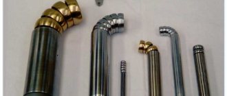
Depending on the design, the tool shank may have the corresponding designation:
B.I.
- internal cone with groove;
BE
- outer cone with claw;
AI
- internal cone with a hole along the axis;
AE
- external cone with a threaded hole along the axis;
BIK
- internal cone with a groove and a hole for coolant supply;
VEK
- outer cone with a foot and a hole for coolant supply;
AIK
- internal cone with a hole along the axis and a hole for coolant supply;
AEK
- external cone with a threaded hole along the axis and a hole for coolant supply.
INSTRUMENTAL MORSE AND METRIC INTERNAL CONES (GOST 25557-2006) INTERNAL AND EXTERNAL CONES WITH TAPER 7: 24 (GOST 15945-82)
Tolerances of internal and external cones with taper 7:24
according to GOST 19860-93.
TOOL CONES Maximum deviations of the cone angle and tolerances of the cone shape (GOST 2848-75)
The degree of accuracy of tool cones is indicated by the tolerance of the cone angle of a given degree of accuracy according to GOST 8908-81 and is determined by the maximum deviations of the cone angle and tolerances of the cone surface shape, the numerical values of which are indicated below.
Notes: 1. Deviations of the cone angle from the nominal size are placed in “plus” for external cones, in “minus” for internal ones. 2. GOST 2848-75 for external cones also provides accuracy levels AT4 and AT5. Tolerances in accordance with GOST 2848-75 apply to tool cones in accordance with GOST 25557-2006 and GOST 9953-82.
An example of the designation of a Morse cone 3, degree of accuracy AT8:
Morse 3 AT8 GOST 25557-2006
The same for a metric cone 160, degree of accuracy AT7:
Meter.
160 AT7 GOST 25557-2006 The same shortened cone B18, accuracy degree AT6:
Morse B18 AT6 GOST 9953-82
Similar documents:
GOST 2848-75 - Tool cones. Tolerances. Methods and means of control GOST 7343-72 - Tool cones with a taper of 1:10 and 1:7. Dimensions GOST 10079-71 - Conical reamers with a conical shank for Morse tapers. Design and dimensions GOST 22774-77 - Grinding cones and tubes. Types and sizes GOST 25548-82 - Basic standards of interchangeability. Cones and conical joints. Terms and Definitions
What is slope?
As previously noted, slope can be considered a rather important indicator. It is represented by a line that is located at an angle to the horizon. If we consider the taper in the drawing, then it is represented by a combination of two differently directed slopes, which are combined with each other.
The concept of slope has become very widespread. In most cases, to display it, a triangle with a certain angle is constructed.
Two auxiliary sides are used to calculate the angle, which determines the inclination of the main surface.
Taper
The ratio of the difference in diameters of two cross sections of a cone ( Dd.
) to the distance between them ( l
) (Fig. 6.39,
a
) is called
taper
(
K
)
: K =
(
D – d
)
/l. Rice. 6.39. Constructing a taper and applying this value For example, a conical element of a part with a larger base diameter of 25 mm, a smaller base diameter of 15 mm, and a length of 50 mm will have a taper K =
TONE CALCULATOR
Taper is the ratio of the difference in diameter to the length (height) of the cone. For example, a taper of 1:10 means that D - d = 1, and L(h) = 10. And a taper of 7:24 means that D - d = 7, and L(h) = 24.
Figure 1 - Cone diagram.
A cone is a geometric body that is obtained by rotating a straight line (forming a cone) located at an angle to the axis of rotation. Taper cannot be measured. Measure the angle that corresponds to the specific taper. For example, a 1:10 taper angle would be 5° 43′ 29.3″ (5 degrees 43 minutes 29.3 seconds). 1 angle contains 60 minutes, and 1 minute contains 60 seconds. In production, angles are measured with a tool called a protractor.
Using the calculator on this page you can calculate any taper. This is often necessary when the drawing does not have enough dimensions, and the drawing is not in vector format. Also, for example, it may be necessary to identify the taper on an existing product (pin, tool, etc.). Normal tapers are presented in GOST 8593-81. Instrumental tapers are presented in GOST 25557-2006. Among the instrumental cones, Morse cones stand out. In Russian standards they are designated KM0-KM7 (KM7 is not recommended for use). In German standards MK0-MK7. In English standards MT0-MT7. When calculating, the following letter designations are used:
- D is the largest base of the cone;
- d is the smallest base of the cone;
- L is the length of the cone;
- α is the cone angle;
- α/2 - slope angle.
Table 1 - Normal and instrumental tapers
| Taper | Cone angle | Slope angle |
| 1 : 500 | 0° 6′ 52.5″ | 0° 3′ 25.25″ |
| 1 : 200 | 0° 17′ 11.3″ | 0° 8′ 35.65″ |
| 1 : 100 | 0° 34′ 22.6″ | 0° 17′ 11.3″ |
| 1 : 50 | 1° 8′ 45.2″ | 0° 34′ 22.6″ |
| 1 : 30 | 1° 54′ 34.9″ | 0° 57′ 17.45″ |
| 1 : 20 | 2° 51′ 51.1″ | 1° 25′ 55.55″ |
| 1 : 15 | 3° 49′ 5.9″ | 1° 54′ 32.95″ |
| 1 : 12 | 4° 46′ 18.8″ | 2° 23′ 9.4″ |
| 1 : 10 | 5° 43′ 29.3″ | 2° 51′ 44.65″ |
| 1 : 8 | 7° 9′ 9.6″ | 3° 34′ 34.8″ |
| 1 : 7 | 8° 10′ 16.4″ | 4° 5′ 8.2″ |
| 1 : 6 | 9° 31′ 38.2″ | 4° 45′ 49.1″ |
| 1 : 5 | 11° 25′ 16.3″ | 5° 42′ 38.15″ |
| 1 : 4 | 14° 15′ 0.1″ | 7° 7′ 30.05″ |
| 1 : 3 | 18° 55′ 28.7″ | 9° 27′ 44.35″ |
| 1 : 1.866025 | 30° 0′ 0″ | 15° 0′ 0″ |
| 1 : 1.207107 | 45° 0′ 0″ | 22° 30′ 0″ |
| 1 : 0.866025 | 60° 0′ 0″ | 30° 0′ 0″ |
| 1 : 0.651613 | 75° 0′ 0″ | 37° 30′ 0″ |
| 1 : 0.500000 | 90° 0′ 0″ | 45° 0′ 0″ |
| 1 : 0.288675 | 120° 0′ 0″ | 60° 0′ 0″ |
| Metric cone | ||
| 1 : 20 | 2° 51′ 51.1″ | 1° 25′ 55.55″ |
| Morse taper No. 0 | ||
| 1 : 19.212 | 1° 29′ 27″ | 0° 44′ 43.5″ |
| Morse taper No. 1 | ||
| 1 : 20.047 | 1° 25′ 43″ | 0° 42′ 51.5″ |
| Morse taper No. 2 | ||
| 1 : 20.020 | 1° 25′ 50″ | 0° 42′ 55″ |
| Morse taper No. 3 | ||
| 1 : 19.992 | 1° 26′ 16″ | 0° 43′ 8″ |
| Morse taper No. 4 | ||
| 1 : 19.254 | 1° 29′ 15″ | 0° 44′ 37.5″ |
| Morse taper No. 5 | ||
| 1 : 19.002 | 1° 30′ 26″ | 0° 45′ 13″ |
| Morse taper No. 6 | ||
| 1 : 19.18 | 1° 29′ 36″ | 0° 44′ 48″ |
| Taper 7:24 | ||
| 1 : 3.42857143 | 16° 35′ 39″ | 8° 17′ 49″ |
| Taper of conical threads | ||
| 1 : 16 | 3° 34′ 48″ | 1° 47′ 24″ |
Cone 1:500 and 1:200 are used for the manufacture of fasteners for permanent connections subject to vibration and variable impact loads, conical mandrels. Cone 1:100 is used for the manufacture of fasteners for permanent connections subject to vibration and quiet variable loads, wedge keys, and conical mandrels. Cone 1:50 is used for the manufacture of conical pins, mounting pins, and attachment handles. The 1:30 taper is used for making spindle journal tapers. Cone 1:20 is used for the manufacture of metric cones in machine spindles and mandrels. Cone 1:16 is used for the manufacture of metric and inch conical threaded connections. Cone 1:15 is used for the manufacture of conical connections of parts under axial loads, connections of pistons with rods. The 1:12 cone is used for the manufacture of tapered mounting bushes for ball and roller bearings. Cone 1:10 is used for the manufacture of conical connections of parts under loads perpendicular and parallel to the axis, ends of shafts of electrical and other machines, adjustable bushings of spindle bearings. Cone 1:7 is used for valves in the valve industry. Cone 1:5 and 1:3 are used for the manufacture of easily removable conical connections for loads perpendicular to the axis, conical friction clutches. Cone 1:1.5 is used for the manufacture of heavy screw pipe connections with a conical seal. The 30° cone is used for the manufacture of friction clutches for drives, clamping collets, and busbar bolt heads. A 60° cone is used to make center holes. The 75° cone is used for the manufacture of internal cones of pressure nuts in connections of high-pressure pipes, external centers of tools with a diameter of up to 10 mm. The 90° cone is used for the manufacture of ends of processed shafts and rollers, cones of valves and valves, center holes for heavy work, countersunk rivet heads with a diameter of 1 - 10 mm. The 100° cone is used for making wood screws. The 120° cone is used for the manufacture of countersunk heads of rivets with a diameter of 2 - 5 mm, internal chamfers of threaded holes, cones for packing oil seals, and throttle valves.
Figure 2 - Designation of taper in the drawing.
The cone icon must be directed in the direction of decreasing diameter.
Determination of cone angle cone dimensions D
d
L
cone angle α expansion of cone angle °
'
«
slope angle α/2 decomposition of slope angle °
'
“
definition of small diameter 1: DL small diameter d
You can see what lathe settings for processing a cone exist on this page.
Cone angle
An important indicator when constructing various drawings is the cone angle. It is determined by the ratio of the large diameter to the smaller one. This indicator is calculated for the following reasons:
- At the time of processing, the master must take this indicator into account, since it allows him to obtain the required product with high dimensional accuracy. In most cases, processing is carried out taking into account the angle, and not the indicators of large and small diameter.
- The cone angle is calculated at the time of project development. This indicator is plotted on the drawing or displayed in a special table, which contains all the necessary information. The machine operator or foreman does not carry out calculations at the production site; all information must be indicated in the developed technological map.
- Checking the quality of a product is often carried out on a small and large basis, but tools can also be used to determine the taper index.
As previously noted, in the mechanical engineering field the indicator is standardized. In another area, the value may differ significantly from established standards. Some products are characterized by a stepped surface arrangement. In this case, it is quite difficult to carry out calculations, since there is an intermediate diameter.
Formula for determining taper
You can independently calculate the taper by using various formulas. It is worth considering that in most cases the indicator is indicated in degrees, but it can also be expressed as a percentage - it all depends on the specific case. The calculation algorithm is as follows:
- K=Dd/l=2tgf=2i. This formula is characterized by the fact that the taper is characterized by a double slope. It is based on obtaining the value of the major and minor diameters, as well as the distance between them. In addition, the angle is determined.
- Tgf=D/2L. In this case, the length of the segment that connects the large and small diameters, as well as the indicator of the large diameter, is required.
- F=arctgf. This formula is used to convert the indicator to degrees. Today, in most cases, degrees are used, since they are easier to maintain when directly carrying out constructions. As for percentages, they are often indicated to enable the calculation of one of the diameters. For example, if the ratio is 20% and a smaller diameter is given, then you can quickly calculate the larger one.
As previously noted, the 1:5 taper and other indicators are standardized. For this, GOST 8593-81 is used.
What is taper? Formula for calculating taper. Designation of taper in drawings.
Taper . Taper is the ratio of the diameter of the base of the cone to the height. The taper is calculated using the formula K=D/h, where D is the diameter of the base of the cone, h is the height. If the cone is truncated, then the taper is calculated as the ratio of the difference between the diameters of the truncated cone and its height. In the case of a truncated cone, the conicity formula will look like: K = (Dd)/h.
Designation of taper in drawings . The shape and size of the cone is determined by drawing three of the listed dimensions: 1) the diameter of the large base D; 2) diameter of the small base d; 3) diameter in a given cross section Ds having a given axial position Ls; 4) cone length L; 5) cone angle a; 6) taper with . It is also allowed to indicate additional dimensions in the drawing as a reference.
The dimensions of standardized cones do not need to be indicated on the drawing. It is enough to indicate in the drawing the symbol of the taper according to the relevant standard.
Taper, like slope, can be indicated in degrees, as a fraction (simple, as a ratio of two numbers or as a decimal), or as a percentage. For example, a 1:5 taper can also be expressed as a 1:5 ratio, 11°25'16", with a decimal of 0.2 and a percentage of 20. For tapers used in mechanical engineering, OCT/BKC 7652 specifies a range of normal tapers. Normal tapers - 1:3; 1:5; 1:8; 1:10; 1:15; 1:20; 1:30; 1:50; 1:100; 1:200. Also 30, 45, 60, 75, 90 and 120° can be used.
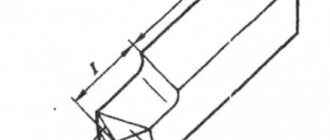
Slope
Flat surfaces of parts located obliquely are indicated in the drawing by the magnitude of the slope. We will show you how to calculate this value with an example. The wedge shown in Fig. 6.40, I, has an inclined surface, the slope of which must be determined. From the size of the largest height of the wedge, subtract the size of the smallest height: 50 – 40 = 10 mm. The difference between these values can be considered as the size of the leg of a right triangle formed after drawing a horizontal line in the drawing (Fig. 6.40, b
). The magnitude of the slope will be the ratio of the size of the smaller leg to the size of the horizontal line. In this case, you need to divide 10 by 100. The slope of the wedge will be 1:10.
Rice. 6.40. Determining the magnitude of the slope In the drawing, slopes are indicated by a sign and the ratio of two numbers, for example 1:50; 3:5.
If you want to depict in a drawing a surface of a certain slope, for example 3:20, draw a right triangle, one of the legs of which is three units of length, and the second is 20 of the same units (Fig. 6.41).
Rice. 6.41. Constructing slopes and applying their values When drawing parts or when marking them, to construct a line along a given slope, it is necessary to draw auxiliary lines. For example, to draw a line with a slope of 1:4 through the end point of a vertical line (Fig. 6.42), a straight line segment 10 mm long should be taken as a unit of length and four such units should be set aside along the continuation of the horizontal line (i.e. 40 mm ). Then draw a straight line through the extreme division and the top point of the segment.
Rice. 6.42. Drawing a line along a given slope The top of the slope sign should be directed towards the slope of the surface of the part. The sign and dimension number are placed parallel to the direction in relation to which the slope is given.
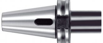
What is the Morse cone notated for?
Denote Morse cones
conventional numbers 0, 1, 2, 3, 4, 5, 6. In addition, GOST 9953-82 establishes the dimensions and designations of shortened
Morse cones
.
They are designated
B7, B10, B12, B16, B18, B22, B24, B32, B45, where the number corresponds to the approximate largest diameter
of the cone
.
Interesting materials:
When is it better to take sumamed in the morning or evening? When is the best time to take Supradin vitamins? When is the best time to plant winter onions? When is it better to plant tree seedlings in spring or autumn? When is the best time to get a haircut based on the day of the week? When is the best time for a retiree to retire? When is the best time to catch perch? When is the best time to ask a girl out? When is the best time to plant oak? When is the best time to plant cucumbers?
History of the definition of a cone
Geometry as a science emerged from the practical requirements of construction and observations of nature. Gradually, experimental knowledge was generalized, and the properties of some bodies were proven through others. The ancient Greeks introduced the concept of axioms and proofs. An axiom is a statement obtained through practical means and does not require proof.
In his book, Euclid gave a definition of a cone as a figure that is obtained by rotating a right triangle around one of its legs. He also owns the main theorem that determines the volume of a cone. This theorem was proven by the ancient Greek mathematician Eudoxus of Cnidus.
Another mathematician of ancient Greece, Apollonius of Perga, who was a student of Euclid, developed and expounded the theory of conic surfaces in his books. He owns the definition of a conical surface and a secant to it. Schoolchildren today study Euclidean geometry, which has preserved the basic theorems and definitions from ancient times.