The quality of a weld is determined by several characteristics, including: the presence of cavities inside, width, thickness, degree of convexity and others. The criteria and parameters differ depending on the type of weld. For a rectangular joint, one of the main parameters is the leg. It characterizes the strength of the connection and the area of heating of the metal during the welding process.
What does leg mean in a welding joint?
The best way to obtain strong and durable joints of metal products is to weld them. But the joining of individual parts into integral structures must be carried out in accordance with current standards. Whether massive and large metal structures can withstand constant operating loads directly depends on the leg of the welding joint.
What is a leg in welding and what functions does it perform in finished products? If we consider the joint formed by fillet welding in section, then ideally it should recreate an isosceles triangle. The distance from the beginning of one butt joint to the end of the second indicates the leg of the weld.
In other words, the leg of a weld during welding is the length of the plane of the largest triangle with equal sides that does not extend beyond the cross section.
The strength of the suture joint directly depends on the size of the leg. For example, the strength will be insufficient with a minimum value of the leg due to the small cross-sectional area, and with an excessively large value, metal deformation may occur due to the increased volume of deposition. Also, a large value entails increased consumption of electricity and materials used for welding.
Types of welding joints and geometry of corner joints
The place of adhesion between parts, created by melting and subsequent cooling of the metal, is called a welding seam. Depending on the configuration and arrangement of the workpieces, seams are divided into butt and corner. The first type connects two elements at the ends in one plane, the second one forms an angle between the workpieces to be welded.
The main geometric parameters of corner joints are:
- thickness, consisting of penetration depth and convex part;
- width - the size of the welded line between two parts in cross section;
- height - the distance between the beginning of the joint and the hypotenuse;
- convexity - the length of a line drawn from the hypotenuse to the highest and convex point of the suture joint;
- root - the part of the deposit that is furthest away from the surfaces of the joined elements;
- penetration depth - determined by the gap filled with metal without taking into account the convexity;
- weld leg during welding - the distance between the edge of the joint and the surface of the second workpiece.
There are a number of specialists, especially novice welders, who simply do not understand what a weld leg is and believe that to increase the strength of the joint it is enough to increase the amount of deposition. But such an opinion is a big mistake, and the more metal is deposited, the higher the risk of overheating of the material.
Influence of welding speed and mode
There is a dependence of the weld cross-section configuration on the process parameters:
- As the current increases at a constant voltage, the temperature increases, so the penetration depth becomes greater. But with excessive amperage, metal can be burned.
- An increase in voltage at a constant current leads to an increase in the length. If there is an excess, lack of penetration is possible.
- As the speed of movement of the electrode increases, the heating temperature of the metal decreases. The seam width and penetration depth are reduced. At speeds above 50 m/h, the lack of temperature leads to the formation of defects that make the seam weak.
- The viscosity of the electrode material affects the shape of the amplification. The higher it is, the more convex the surfacing becomes.
We recommend reading: How to calculate the strength of a weld
The welding mode is selected according to the workpiece with the smallest thickness, so as not to burn through it.
Leg calculation
To avoid mistakes and produce a truly high-quality metal structure that can withstand high loads, it is necessary to first calculate what the leg of the weld should be.
The strength characteristics of the products being created directly depend on this indicator, in particular:
- it is impossible to increase deposition, since this will significantly change the strength characteristics for the worse;
- If you increase the coverage width, the heating area immediately expands and, accordingly, a larger amount of metal melts. As a result, this causes deformation of the entire structure;
- too large width and height of welds significantly increase the amount of consumable materials, and if we are talking about mass production, then such costs are simply unacceptable;
- when welding workpieces of different thicknesses, it is very important to determine the value of the leg, and it must be calculated taking into account the geometric parameters of the part that is thinner;
- seam joints that are too narrow do not have adequate strength and reduce the quality of the entire structure. This is especially important in cases where finished products will be subject to constant loads.
Calculation of the leg of the weld allows us to determine, even before the start of welding work, what strength properties the metal structure will have. In addition, from a financial point of view, the presence of such indicators is necessary. You can calculate the cost of work down to the penny, providing savings on the consumption of electricity and components.
Criteria for choosing a welding joint leg
The length of the weld is calculated separately for each of the elements to be soldered. The result obtained directly depends on a number of characteristics:
- thickness of parts connected to each other;
- the material from which the workpieces are made;
- type of connection - one- or two-sided, depending on how many sides the corner is welded;
- technical characteristics of consumables, in particular wire and electrodes.
To ensure the required strength, it is important to correctly determine the dimensions of the roller. Excessive or minimum weld length is considered unacceptable; it must comply with current standards.
Influence of the leg on the geometric parameters of the fillet weld
In addition to strength indicators, the leg of a fillet weld affects the correct geometry of the joints created:
- When one side of a butt joint is too elongated, it is a sign that only one workpiece has melt applied to it, and the other workpiece is poorly attached. Therefore, it is important that the legs are the same on both sides. Defects of this nature arise due to the displacement of the arc to the right or left;
- a stretched and flat bead indicates that the molten metal has spread chaotically over the surface of the parts. This is also considered a defect formed due to an excessively short arc;
- with very short legs, large bulges form at the butt joints. Such defects occur with a long arc, the metal freezes on top and even under small loads cracks immediately appear.
To obtain an ideal weld, along with control over geometric parameters, you must also follow the welding technology. The arc after ignition must be located strictly in the center of the joint being created. The optimal arc length is considered to be 1-1.5 based on the diameter of the electrode.
The speed of movement and the shape of the weld pool must be controlled. The bath should have an oval shape. If visually it resembles a circle or is too elongated, then this is a direct sign of an incorrect welding process. Lack of metal penetration occurs due to the high speed of electrode movement. When the speed is very low, there is a high probability of metal burns.
Each of the above factors is extremely important in the welding process. But if you follow the welding technique and know what the size of the weld leg should be, it is not difficult to make high-quality butt joints that ensure the reliability and durability of any structure.
What affects the weld leg
The formation of the weld leg of corner and T joints is influenced by a number of factors:
- Directionality of the torch or electrode.
If you weld fillet welds while holding the electrode or torch at an angle of 45º, then the liquid metal will flow down to the bottom shelf under the influence of gravity, lowering the vertical leg. Experienced welders in this case change the angle by 20-30º, directing the end of the electrode to a vertical surface. This is how you can change the height of the leg and achieve an equilateral triangle in the cross-section of the seam. - Position of the product in space.
It is easier to obtain a uniform seam on a corner joint by placing the product “in a boat”. Then the surface of the weld pool is smooth, the metal does not flow anywhere and covers both sides being joined equally.
- Arc speed.
When carried out quickly, the seam turns out to be narrow, and the leg is often small. Welding with a delay leads to an increase in the height of the seam and the growth of the leg. The welding speed must be selected on the rough workpiece, having tried different options, and only then move on to welding the critical product.
- Current strength.
Low current strength facilitates the application of filler metal from above, without deep penetration. The leg turns out to be large, but the quality of the connection is poor. Too high a welding current leads to deep penetration, but increases the fluidity of the metal and promotes undercuts on the vertical side, which is also a defect.
- Inductance.
Determines the transfer rate of a drop of molten metal during semi-automatic welding. The correct settings help to warm up the part well, apply a neat seam, and reduce spattering.
- Characteristics of filler metal.
If the core of a consumable electrode or the wire of a semi-automatic machine has high-temperature additives, then the weld pool becomes thicker, which leads to the growth of the leg. Low-temperature alloys flow faster, reducing the height of the weld leg.
How to calculate the leg of a welding joint
What a weld leg is in welding and how it affects the technical characteristics of products obtained during the welding process can be understood from the material presented above. Therefore, doubts about carrying out calculations of this parameter are unnecessary.
The values of welding joints and their strength indicators in industrial conditions are calculated mathematically, using special formulas for this.
At home, measurements can be performed using a ready-made specialized cathetometer template. This is a device consisting of calibrated plates. Each plate is applied in turn perpendicular to the joint line, the result is determined by the one that fits most closely to the surfaces.
If the master does not have a cathetometer at hand, then you can use a square and a caliper instead. A square is applied to one of the workpieces, and its top should rest against the top of the bead obtained during welding. You need to lower the caliper probe to the other peak. The leg of the weld is measured using the reach of the probe, which is equal to the calculated length.
Here you should pay attention to the fact that in the presence of long suture beads, checking takes a lot of time, and the measurements themselves are not highly accurate.
Other ways to visually calculate leg
There are several effective methods for measuring the leg of a weld, the essence of which is based on physical principles. These include ultrasonic testing, flaw detection, scanning of joints with x-rays and gamma rays, and the radiographic method.
The capillary method and magnetic zoning are sometimes used to determine the leg of the weld. But such methods are very expensive, since control requires expensive reagents and equipment.
There are also special computer programs that allow you to quickly perform the necessary calculations and obtain accurate indicators. In this case, you will need to first measure the geometric characteristics of the welding joint. This can be done using universal templates visually:
- Krasovsky USHK-1 device . Used for measuring gaps between parts to be welded, dimensions of butt, T-joints and overlap joints;
- UShS-2 measuring device . This is a set of templates with which the welding leg is determined by the convex hypotenuse with a range of 4-14 millimeters;
- UShS-3 device . The measurement process with it is more complicated. With its help, the indicators of the angles of cutting seams, the height of the weld and the displacement between the connected elements are checked;
- template equipped with a Marshak-Usherov UShS-4 measuring device . Designed for taking measurements of the weld root, angles and leg size. Among all devices it is considered the most universal.
Do not underestimate the definition of “what is a weld leg”, because the quality of work, the strength of the connecting joint and the entire structure as a whole directly depend on it.
The visual method of obtaining geometric values does not require special skills and the use of expensive equipment, and is also the most financially accessible way to check welded products for compliance with the technical specifications.
Control methods
Welding seam control is an integral part of the technological process. First of all, the connection must be examined for resistance to destructive loads. Forms of control can be different. They depend on the principles on which they are based. Advanced techniques include radiography, x-ray, gamma ray, ultrasonic and eddy current testing. Magnetic probing should also be added here, as well as the capillary method of examining seams. The presented types of control require expensive equipment and cannot always be implemented, especially in small-scale production conditions.
A ready-made template can serve as a handy device for measuring legs. To be precise, it is not just one template that is of practical importance, but a whole set.
In its simplest design, the template is a set of plates held together at one end. At the other end there are slots corresponding to the shape of the cross section of the seam. The master one by one applies the templates to the workpiece and determines the most appropriate one. Each template is marked with the size of the corresponding leg.
There are several other devices that, by their operating principle, represent templates, only the way they measure legs is slightly different. The Krasovsky template is designed to determine the gaps between workpieces. Universal welder's template (UNS-2) - a set of plates with cutouts. The length of the legs can be determined by the shape of the convex hypotenuse. The Marshak-Usherov template allows you to measure not only the leg, but also determine the root of the seam. This device is considered the most versatile of all those described above.
How to calculate a leg taking into account the thickness of the source material
In order to accurately calculate the size of the weld leg from the thickness of the metal, it is necessary to select the triangle line taking into account the dimensions of the products themselves, the type and position of the junction. Each detail is selected individually, but it is imperative to be guided by general principles.
In order for the connection to be reliable and thorough, both sides of the triangle of equal length must be perpendicular to one another.
The junctions themselves can be different:
- butt: with one-sided, curved, V or X-shaped bevel, or without bevel of edges at all;
- made with overlap;
- end;
- angular: there must be an angle of at least 30°, double- or single-sided with straight edges, with two or one beveled edge;
- T-bars: with or without bevels (one or two), with right or acute angles, single- and double-sided.
Among the types of joints listed above, calculating the leg of the weld depending on the thickness of the metal is permissible only for T-joints, lap joints and corner joints.
If it is necessary to join elements of different dimensions, then the leg of the weld should be taken according to the smallest thickness of the parts being welded.
In cases where the welded structure will not be subjected to heavy loads, the dimensions of the seam joint can be determined by the thickness of the material. For example, when connecting elements with a thickness of each about 4-5 mm, the approximate leg should not exceed 4 millimeters. If the workpieces are thicker within 5-6 mm, then the maximum value is 5 mm.
Calculating leg dimensions is important in enterprises and factories during mass production of metal structures. Having the necessary values available, you can avoid defects and also significantly reduce production costs.
How to measure a seam leg
Measurements allow you to control the quality of work during its implementation or upon completion. They make it possible to objectively evaluate the result obtained and determine at what stage mistakes were made.
The size of the joints is determined based on geometric formulas. To obtain the result, it is necessary to calculate the leg of an equilateral triangle of the maximum size that can be inscribed in the cross-section of the connected elements.
Calculations can be done in different ways. When choosing an option, the welding method is taken into account. For example, if there is an overlap and two metal sheets 4 mm thick are connected, then the leg will also be approximately the same thickness. In other cases, the size of the leg is approximately 40% of the metal thickness.
Calculation of leg size using mathematical formulas
There are many mathematical methods for calculating the leg of a weld. There are separate formulas for almost every type of joint and, if necessary, they can be found on the Internet on specialized sites without any problems, just as the table of weld legs is in the public domain for users.
If we consider the bead as a triangle, then the square of the leg in it is similar to the volume of the deposit. For example, when the length of the junction is 10 mm and the leg (K) is increased by only 1 mm, then by as much as 20% more wire will be required.
When joining parts up to 4 millimeters thick, the overlap K should be equal to 4 mm. At the highest value, you need to calculate 40% of the thickness and add 2 mm to the result.
But before choosing a weld leg, we must not forget that fillet welds come in several varieties:
- normal , on which there are no concave and convex areas. In this case, the leg is similar to the thickness of the metal;
- concave _ Here the weld leg is minimal and amounts to 0.85;
- convex _ To find out what the optimal thickness of the welded leg is, the calculation is carried out using the formula: K = S x cos45°. The symbol S denotes the width of the junction, and cos45° is a constant value of 0.7071;
- special , in which the triangle of the roller is not scalene.
To calculate the leg of a weld with maximum accuracy depending on the thickness of the metal, mathematical operations alone will not be enough. Particular importance is given to the fluidity of the metal being welded and the technology by which welding work is carried out.
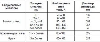
For those who cannot perform quick calculations and find it difficult to choose a weld leg, Table 1 will greatly simplify the work.
For materials with other metal yield strengths, if it is necessary to calculate the minimum leg of the weld, Table 2 will also be useful for use in work.
IMPORTANT! The result obtained from mathematical calculations must be additionally checked with the requirements of GOST 5264-80, GOST 11543-75 and other regulatory materials for the geometry of seam joints.
How to calculate the leg size for a 1 m connection
When performing welding work at home, it is enough to measure the thickness of the material by 1-1.15 mm on the side and approximately determine the leg of the weld from it; a table with ready-made parameters will also be a good helper for novice welders. But the calculations performed in this way are rather conditional, based on assumptions.
Professional welders working at large industrial enterprises do not need to explain what a leg is when welding a seam and what its importance is. The main purpose of design calculations in the mass production of objects and structures made of metal alloys is to determine the appropriate size of the weld in relation to specific indicators of axial stress and elongation of the material.
To calculate the size of the deposited filler according to the tensile load, use the following formula: L = F/ ρ x [ρ] , in which L is the length of the weld weld, F is the future load on the welding joint to which the seam will be subjected, Ρ is the maximum permissible load on joint during operation of the finished product.
To calculate the acceptable length from axial stress, there is another formula: L = F/0.7K x ρ
How to determine the leg of a weld from this formula? By simple mathematical operations, you can derive a new formula, according to which K = 0.7 x L x ρ
Considering that we need to determine the dimensions of the leg for one meter of weld surfacing, the final result will be K = 0.7 x ρ
If you carefully analyze the given calculation procedure, the conclusion becomes obvious - the size of the leg directly depends on the permissible load on the connecting seam. You can find out the permissible load standards when welding using different methods using special tables.
Already at the stage of developing design documentation, the thickness of the welding seam is required; the calculation of the indicator is carried out taking into account:
- class and type of welding;
- brands of electrodes used;
- permissible current load standards;
- indicators of axial stress and stretching;
- weld reinforcement height.
Based on these values, a drawing of the connecting joint is created, the dimensions and technical characteristics of the joined elements are specified. Also, during the design process, the weld leg is calculated based on the smallest thickness of the parts being welded, which makes it possible to optimize the cost and improve the quality of the welding process.
Seam geometry
The weld leg must comply with the geometric parameters specified in the regulatory documents. They are also used to carry out mathematical calculations of the main geometric characteristics using formulas and tables.
Weld parameters.
The geometry of the welding joint is determined by the type of connection. The cross-section of the joint will depend on the type and size of the parts being welded.
In production, all parameters and strength of joints are calculated using formulas. At home, you can limit yourself to ready-made templates.
The most convenient and widespread is the universal template, which is a set of plates fastened together. Applying them alternately to the surface of the products, select the one that fits most tightly to them.
When welding metal structures that do not require high strength and reliability, the minimum weld size is determined based on the thickness of the metal.
It is very easy to assess contact by eye. It usually corresponds to the thickness of the metal. So, for welding products with a thickness of 7 mm, the leg should also be 7 mm. You can make more accurate calculations using the appropriate formula.
After performing the calculations, select the required current and voltage, and then begin welding.
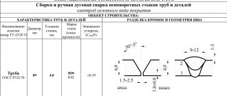
GOST butt weld legs
In order for metal structures to withstand the loads placed on them during operation, all seam joints present on them must comply with standard indicators.
The main document regulating the dimensions of welded joints, as well as the types and characteristics of structural elements of metal products is GOST.
It is clearly stated here that if it is necessary to join parts of different thicknesses, they can be joined in the same way as workpieces of equal thickness. Only in this case the difference between the two indicators should not exceed standard values.
One of the GOST clauses stipulates the permissible displacements of the edges relative to each other and establishes clear parameters for the displacements in accordance with the thickness of the workpiece. The appendix to the document describes all possible minimum sizes of legs, which must be taken into account when welding metal structures.
Welded joints
To date, more than 150 methods of connecting parts using electric welding have been developed and mastered. But the technology does not stop there, and various innovative methods are constantly being introduced. Almost all attention is focused on the weld, as the area of the junction of two metals, formed during their crystallization. Depending on the relative orientation of structural elements relative to each other, several types of welds are distinguished. In the most trivial classification they are divided into corner and butt.
- Corner joints are formed with T-joints, cross joints or directly corner joints. Such seams are formed after one-sided or two-sided cutting of the edges. The cutting method depends on the dimensions of the structure. Such joints can be divided into continuous and discontinuous, depending on the type of longitudinal section.
- A butt joint involves welding two products adjacent to each other at their ends. An overlap seam is a special case of a butt joint. The edges of the parts can be beveled or remain straight. The most common are horizontal seams. If the thickness of the parts does not exceed 8 mm, the edges are not cut.
Consequences of incorrect calculation of the welded leg
Beginner welders quite often make mistakes in carrying out calculations, as a result of which they receive incorrect values for the dimensions of the leg. In cases of manufacturing simple structures, minor deviations do not pose any danger. When mistakes are made when creating large load-bearing structures, the consequences can be irreparable. Therefore, the task of primary importance during welding work is to calculate with impeccable accuracy the parameters of the joints and, in particular, the leg of the weld (what this is is described in more detail above).
Any excess deposition along the connection line reduces strength, causes spattering of molten metal, the formation of sagging on the surface of parts, and also increases the consumption of electrodes and electricity.
But the biggest problem with incorrectly performed calculations is that even under minor loads the structure will begin to collapse and its further operation will be impossible.
Qualitative parameters of welding work
To make a high-quality welded joint, you need to know its parameters. One of these parameters is the leg. It is the observance of its size that allows the future product to withstand static and dynamic influences. The leg of a welding seam is the distance along the plane of one part to the angle of contact with another. But to know this size, it must be calculated correctly.
Leg and other characteristics of the weld
How to check the quality of seams and welding work
To make a welded joint reliable and durable, it is not enough just to correctly calculate the parameters of the leg. It is also important to strictly follow the welding technology and ensure that the seams are uniform and uniform along their entire length.
There are several ways to test a weld leg for strength and durability. The most popular and frequently used are two methods:
- destructive _ Various types of tests are carried out on special mock-ups, the results of which determine the strength of joints and structures as a whole. These may include increased mechanical loads, chemical, metallographic and other studies;
- non -destructive This control method includes visual inspection of the connection, studies using magnetic waves, ultrasound and other specialized equipment.
Visual inspection does not require special skills or expensive equipment. But it is not enough to detect existing defects and inaccuracies. You can avoid the formation of flaws on the weld seam if you follow some rules when creating it:
- there should be no draft or strong wind at the welding site, since these are the first causes of pores in the connecting joint;
- the welding current cannot be exceeded - this disrupts the structure of the metal;
- depending on the thickness of the metal, it is necessary to choose the correct gap;
- It is best to use a short arc;
- when working with direct current, do not allow water to get on the metal or electrodes;
- Make sure that the width of the seam is the same throughout the entire length of the seam. Even with the slightest deviations, the loads will be distributed unevenly and the risks of cracks and complete destruction of the welding joint will increase;
- control the penetration depth, it should be uniform. Otherwise, internal cracks may occur;
- choose the right electrodes for welding. This applies to both the diameter and composition of the metal rod. For convex rollers, electrodes are suitable that, when melted, form a viscous and thick consistency. If the melt is very liquid, the line will be concave.
The quality of welding and the shape of the seam joint largely depend on the operating mode. If you need to increase the depth and reduce the width of the seam, then this can be achieved by increasing the speed of movement of the electrode. When, on the contrary, the depth needs to be reduced and the width made larger, then you simply need to change the voltage.
By adhering to these simple recommendations in combination with correctly performed calculations, you can have no doubt about the quality and high strength characteristics of the welding joint.
Professional welders at large production facilities determine the geometric parameters and technical characteristics of the future weld down to the millimeter. But if welding technologies are violated and control checks are ignored, then even the most accurate calculations of seam joints will not guarantee the quality of welded structures.