Before welding, parts are placed in different spatial positions. One example is the fillet weld. The order of the process and the level of complexity of welding depend on its location relative to the horizon.
A corner connection is formed when parts are installed in the shape of the letter T, end-to-end or overlapping. It is found in most metal structures.
Fillet weld.
Fillet weld welding technology
When working with parts installed at an angle, use classic welding machines. You can use a simple transformer.
The disadvantage is the large size of the equipment. The best option is an inverter. Light weight and wide range of settings make it easier to work with complex seams.
When choosing a technology, take into account that:
- The current strength is set taking into account the diameter of the electrode and the thickness of the parts being connected. At a high value of the parameter, burns occur, at a low value, the rod sticks.
- A uniform, strong seam is obtained with oscillatory movements. Other methods of movement, such as zigzag, are acceptable.
- The ceiling seam is formed under conditions of rapid solidification of the melt. To do this, use a rod with a refractory coating, which is moved in a circular motion. This is not entirely convenient for the welder. As the electrode moves away, the arc weakens and the weld pool decreases. This results in a short circuit. This technology is complicated by overheating of the lower surfaces of the parts. Therefore, it is recommended to refuse it.
Types of fillet welds (welding positions)
Compounds are classified according to many criteria. First of all, this is a method of installing blanks. Depending on the requirements for the strength of the finished structure, the seam is made one- or two-sided.
In the second case, the seam is reliable and holds its shape longer. When welding on one side, the structure may become deformed.
Lower
When working in this way, one part is in a horizontal position, the other in a vertical position. The seam is formed at a right angle between the surfaces.
If the thickness of the workpiece does not exceed 12 mm, cutting the edge is not required, but the lower part of the sheet installed perpendicularly is cut so that the distance between the edges is less than 2 mm. When working with thick parts, a V-shaped cut is made.
Example of a fillet weld.
Vertical and horizontal
When welding parts located vertically, the melt flows down. Reducing the arc length helps eliminate the formation of droplets; to do this, the electrode tip is brought closer to the area being treated.
If the rod does not stick, it can be rested against the part.
Seam welding has the following features:
Vertical welding seam and electrode movement pattern.
- The metal is prepared taking into account the type of connection and the thickness of the workpieces. The parts are secured in the desired position and short tacks are applied. This prevents the structure from moving during operation.
- The seam is formed both from bottom to top and in the opposite direction. The first method is considered more convenient. Under the influence of the arc, the weld pool moves upward. The seam is of better quality.
- Fillet welding can be carried out in a vertical position with arc separation. During the break, the melt has time to cool. In this case, the same movements of the electrode are used as when welding without separation: in different directions, in a circle or in a loop.
- When welding from top to bottom, the rod is installed at a right angle to the surface of the workpiece. After the arc is excited, the part is heated, the tip is released and welding is carried out in this position. The method is not entirely convenient, since it requires constant monitoring. However, the seam acquires the required characteristics.
Horizontal connections can also be formed in different directions. The method is chosen taking into account the preferences of the welder. The bath also moves downwards, so the angle of the electrode is increased, taking into account the welding speed and amperage.
As the melt drains, they make faster movements and periodically tear off the arc. During these breaks, the metal cools down and no drops form. You can try changing the voltage. These methods are used in stages.
We recommend reading: How to calculate the strength of a weld
Horizontal weld seam.
Ceiling seams
This is the most difficult way to form compounds. It requires experience and constant monitoring of the treated area. During the welding process, the electrode is held perpendicular to the ceiling.
The arc length is minimal, the speed of movement is constant. The rod is moved in a circular motion, expanding the melting area.
Welding ceiling seams.
Into the boat
Corner joints often have to be welded on both sides. To carry out the process correctly, the workpieces are installed so that their planes are at the same angle. This method is called boat welding. This simplifies the selection of electrode movements and improves the quality of the seam.
Boat welding.
Electric welding
Practice for amateur craftsmen. Blog of Mikhail Shcherbakov.
Mistakes when making fillet welds
Many amateur welders perform fillet welds with gross errors. This especially applies to novice welders who are just learning this skill. Some time ago, based on a photograph sent by one of my readers, I wrote an article where I examined the errors of performing a weld in the down position. If you haven't read it, read it.
Now, based on a photo from the same reader, I will analyze his fillet weld. In general, a combination of many mistakes leads to this result, but I will still try to structure my story.
No metal at the top of the corner
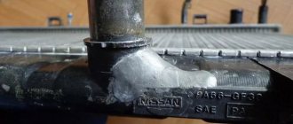
The most basic and conspicuous defect is the absence of weld metal at the top of the corner, i.e., at the junction of the parts.
In photo 1 I have outlined this with red ovals. Photo 1. No weld metal at the top of the corner.
This occurs as a result of incorrect movements of the electrode. In particular, the rapid movement of the electrode at the junction of the parts (at the top of the corner) and prolonged retention on the sides of the seam.
Also, such a defect can also be caused by an incorrectly selected electrode diameter. The fact is that an electrode that is too thick can touch the parts with its edges, so the arc, which always follows the shortest path, will not “reach” the top of the corner. Read more about lack of penetration of a fillet weld here: https://www.elektrosvarka-blog.ru/uglovoj-shov-neprovar-1/
In general, in this situation it would be possible to finish listing the errors, because Against the background of such a gross defect, everything else does not matter much. But let's imagine that there is still metal at the junction of the parts (at the top of the corner).
Then in photo 2 it makes sense to pay attention to the fact that there is significantly less metal on the vertical wall (yellow arrow) than on the horizontal surface (blue arrow). And on the right side of the seam there is no metal at all on the vertical surface (yellow oval), while on the horizontal surface there is quite a lot of it (blue oval).
Fillet weld with different amounts of deposited metal
Photo 2. Different amounts of deposited metal on the vertical and horizontal walls.
This phenomenon occurs when the electrode is at the wrong angle to the workpiece, and the welder does not monitor how much metal is supplied from the electrode to each side of the weld.
Besides this, I see a few more blots, but in this situation they are not at all important.
In fact, the topic of making fillet welds is much broader than it seems at first glance. The fact is that a fillet weld can be placed in different ways in space and welding in each position has its own characteristics. In addition, welding the corner inside and outside also has its own characteristics (correct relative position of parts, gaps, etc.). And, unfortunately, this cannot be conveyed in articles - you need to watch the video.
Classification of seams
Connections are also classified according to the method of edge matching. They are T-shaped, overlapped, end-to-end or point.
We recommend that you read
Existing types of welded joints
Lap joint
This method is used when working with thin sheet metal. The seam is boiled on both sides so that moisture does not penetrate into it and rust does not appear.
When laying parts overlapping, choose the inclination of the electrode correctly, which should be from 15 to 45 degrees. This helps to get a strong, reliable seam.
When deflected upward or downward, the bulk of the melt is displaced. The strength of the connection decreases or a weld seam does not form at all.
Overlap welding.
With edges joining to one point
This method is used when working with sheet metal or pipe ends. The blanks are installed at a distance of 1-2 mm from each other and secured with clamps.
When welding, the gap is filled with melting wire. Thin sheets are welded without additional preparation (cleaning from rust is always mandatory).
When working with thick parts, make a double or single seam, the edges are cut in the following ways:
- The edges of workpieces 4-12 mm thick are processed using any method. One-sided cutting is considered convenient. Thick parts are cut in the shape of the letter V. U-shaped cutting is a more complex method, used less frequently. If there are increased requirements for the quality of the seam and a thickness of more than 8 mm, the edges are cleaned on both sides.
- When welding parts larger than 12 mm, a double connection is required. Such a layer of metal cannot be heated evenly on one side. The edges are cut off on both sides, forming something like the letter X. It is not advisable to use V- or U-shaped methods: a larger volume of melt will be required to fill the gaps. Electrode consumption increases, operating speed decreases.
If thick parts will be joined with one-sided cutting, the melt is applied in several approaches. Such seams are called multilayer.
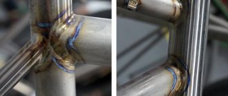
T-joint
This method involves installation in the shape of the letter T. The connection is formed on both one and both sides.
Edge cutting is performed depending on the thickness of the parts:
- for values up to 4 mm, no treatment is required;
- if the thickness is 4-8 mm, make a double seam without cutting;
- a metal layer of 4-12 mm requires the formation of a single seam with one-sided cutting;
- When working with parts thicker than 12 mm, double-sided processing is required.
The fillet weld is considered a type of T-weld. When forming it, the same recommendations are followed: thin sheets are boiled without edge treatment. For greater thickness, remove part of one or both sides.
T-joint welding seams.
With or without edge cutting
Proper welding of corner joints requires careful preparation of the edges of the elements. Joints of thin parts do not require additional measures.
Welded seams with edge preparation.
When welding without cutting, traces of corrosion are removed by brushing the metal until it shines. The edges of products of medium thickness are beveled at an angle of 45° on the attachment plate.
The backing is necessary to retain the additive and increase the strength of the seam. When cutting on both sides, the edge cone is truncated. This protects the edges from sagging and burns.
How to weld
The production of fillet welding is influenced by the location of the plane. Let us characterize the basic methods of conducting the process.
Lower. Here it is more rational to use a technique known as the “boat”. It will give the required quality to the seam; note that even debutants in the field of welding can cope with it.
The configuration is given a V-shape. It becomes like a boat. That’s why the method was called that.
“Boat” almost eliminates the appearance of defects in the form of lack of penetration or undercut edges. You have to try hard for them to suddenly form. In practice, fillet weld welding sometimes takes place in conditions that are not as comfortable as described above.
For example, when T-seams, which have both a vertical and a horizontal surface, are welded with a “boat” at the joint of parts.
Here the quality may already be at risk. Even in a horizontal plane, the top of the corner itself risks remaining poorly cooked. The vertical plane is vulnerable to undercuts.
This will be facilitated by molten iron, which, it is possible, will try to “escape” down. A simple control trick to which the electrode reacts sensitively will prevent undesirable consequences.
Common problems
Novice welders often make mistakes that contribute to the occurrence of defects. Some significantly worsen the quality of the seam, others only affect aesthetic characteristics.
It is necessary to detect defects in a timely manner and eliminate them. The most common problems are uneven filling or differences in seam width. As you gain experience working with fillet welds, errors occur less frequently.
Lack of penetration at the connection point
The defect occurs when the joint is partially filled with melt. This requires timely correction, since the strength of the weld decreases.
We recommend reading Features of an overlap welding joint
The main reasons for lack of penetration are:
- low current setting;
- moving the electrode too quickly;
- improper cutting of edges of thick parts.
To eliminate lack of penetration, increase the power of the arc and reduce its length. If the parameters are selected correctly, the defect will not reoccur.
Example of lack of penetration of a connection point.
Uneven impact
This error is manifested by the formation of pores or sagging. The former are voids located linearly or chaotically, the latter are protruding areas of the melt. Both phenomena are unacceptable because they negatively affect the performance of the finished structure.
The appearance of pores is promoted by:
- improper protection of the weld pool, excessive consumption of inert gas;
- use of low-quality electrodes;
- exposure of the welding zone to wind, which deflects the gas cloud (oxygen in this case reacts with the melt);
- presence of traces of corrosion or dirt on parts;
- improper edge processing.
Sagging occurs when working with filler material due to incorrect selection of welding mode and parameters. These elements are not connected to the main part. It is recommended to remove them mechanically.
Pruning the area
The defect is a depression along the seam. Occurs with increased arc length. The weld pool expands, the temperature is not enough to warm up the edges of the workpieces. The metal immediately hardens, forming undercuts.
To eliminate the defect, reduce the arc length or increase the current.
During fillet welding, an undercut can also occur due to improper holding of the electrode. The melt flows down, causing a groove to appear. In this case, the power of the arc is reduced and shortened.
Welding seam defect.
Seam burn
The defect is a through hole.
Its appearance is facilitated by:
- too much current;
- slow guidance of the rod;
- increased distance between the edges of the part.
To eliminate the defect, select the correct operating parameters of the device and reapply the suture.
Cold and hot cracks
The second type of defects appears during the cooling stage of the metal. They are directed across or along the seam. Cold cracks occur on an already hardened seam when the structure experiences excessive loads.
Such defects lead to gradual destruction of the connection. To eliminate the defects, the seam must be re-formed. If there are a large number of cracks, the edges of the parts are cut off.
Cold cracks during welding.
Incorrect calculations
When choosing incorrect parameters for the operation of the device, different types of defects arise. The seam loses strength and becomes deformed.
The main causes of problems are considered to be:
- Incorrect leg. The quality of the welded joint depends on the correct choice of voltage and the speed of the electrode. The latter must be kept at the same level. If the current is insufficient, the rod operates at low speed, and the base metal does not melt well. At a high value of the parameter, the leg becomes concave and burns are formed.
- Oblique angle. It is quite difficult to install the parts in the desired position. The design loses the required qualities if the tilt of the attachment plate shifts to one of the sides.
Welded corner joints
Section: Uncategorized
A corner connection is obtained when the edge of one part is connected by welding to the edge of another part, forming an angle between each other (usually 90 degrees, but the angle can be at any angle of at least 30°, if less, then it is an end connection).
- Where is it used?
- Advantages and disadvantages
- How to cook, technology Video
- Device: video
with one-sided edge groove
The electrode must be positioned so that the welding arc melts the edges of both parts.
The welder must perform any welded joint efficiently the first time, since any defects obtained during the welding process affect the strength of the weld.
without beveled edges
with two bevels on one edge
single-sided seam with flange on one edge
Where is it used?
Widely used in construction, installation of small to huge structures, mechanical engineering, metal furniture, frames, trusses, containers, reservoirs, bridge construction and much more.
without edge cutting
Advantages and disadvantages
The fillet joint is strong and common, but it is important to note that the fillet weld is also complex and requires certain skills and experience. If the rules for welding fillet welds are not followed, defects will occur in the form
- burns (a through hole in the seam, the cause is high current, the electrode is held in one place, a large gap),
- fistulas (this is a tubular cavity in the weld. Formed due to short circuits of the electrode or sudden interruption of the arc, it can also be caused by the lack of good technological preparation of the parts being welded),
- undercuts (recesses formed due to incorrect welding technique, incorrect position of the electrode, which leads to a weakening of the cross-section),
- lack of penetration (arising due to current strength, high speed of electrode movement, poor-quality stripping, electrode displacement, etc.),
- sagging (dripping metal, also formed due to incorrect welding technique), etc.
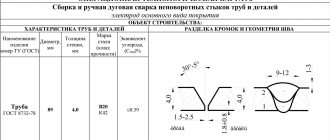
Electrode selection (table)
The diameter of the rod is selected taking into account the thickness of the workpieces being welded. The choice is also influenced by the position of the workpieces, the leg of the seam, the type of connection, and the method of cutting the edges.
The table will help you install the correct electrode.
| Workpiece thickness, mm | 1-2 | 3-5 | 4-10 | 12-24 | 30-60 |
| Rod diameter | 2-3 | 3-4 | 4-5 | 5-6 | 6-8 |
The values are approximate as they depend on many factors. For example, when working with ceiling seams, you should not use elements with a diameter of more than 4 mm. Such rods are not used for multi-pass welding either. This contributes to uneven welding of the edges.
The most optimal technology
The best method for welding corner joints is the “boat” method. This technology allows the arc to reach the root. In this case, you need to properly secure the workpieces. The angle between the welded edges must be straight.
Welding begins from the bottom, gradually moving the weld pool upward. Before cooking, you need to study the movement pattern of the rod. When parts are less than 1.4 cm thick, it is not necessary to bevel the edges. The edges of thicker pieces are cut off.
It is not always possible to install parts for boat welding correctly. When using a different technology, pay attention to the leg of the seam. When its length is up to 8 mm, a single-layer connection is made.
For larger sizes, the seam must be multi-pass. At the first stage, the root is boiled using a thin electrode. After this, the following passes are performed.
Results and conclusions
Lack of penetration will not spoil the horizontal plane in the lower version if you excite the welding arc at a distance of 3 or 4 mm from the very edge of the leg.
Then the arc is directed to the top of the seam and held. Whether your part will cook well depends on following these rules.
To weld a strong fillet weld, you must follow the procedure during its production. Fillet joints are available using almost all types of welding machines.
At the same time, do not forget about safety precautions. Before welding, put on protective overalls and a mask.
About the specifics of the process in general
Before starting welding, you need to prepare the joints. They should form a right angle. One part is placed horizontally, the other – vertically.
We recommend reading Calculation of the weld leg during welding
The edges of T-shaped structures require mandatory cutting. However, this step is skipped when working with lap seams. The connection is formed in the corners formed when metal sheets are placed on top of each other.
The classic fillet weld consists of two structural elements connected to each other. In this case, cutting off the end of one of them is required.
Cutting edges for butt joints.
Preparatory work
Before starting fillet welding, preparation is carried out. If, during a visual inspection, dirt, scale, or rust are observed on metal parts, then they must be cleaned. Particular attention is paid to the welded areas. For these works, brushes with metal bristles, solvents, grinding tools and blowing with compressed air are used.
A corner welded joint will be more reliable if you trim the end that is supposed to be connected to the surface of the second part. When installing elements, it is advisable to use tacks on both sides. This prevents the occurrence of distortions and deformations. Before starting the process, you need to choose the electrodes wisely. This depends on the thickness of the metal sheets and the number of layers.
Welding instructions
Welding of T-joints is carried out as follows:
- Prepare the equipment. Using special tables, current and voltage are set.
- Install the electrode. In one plane, the rod should tilt in the direction of its movement.
- Excites an electric arc. When using the argon-arc method, gas supply begins.
- Make small potholders. After they cool, the formation of a continuous connection begins.
- Start finishing the seam.
Cleaning welds
After completion of work, particles of metal, slag and scale remain on the surfaces. The seam protrudes slightly above the surface, which impairs the aesthetic qualities of the structure. Such defects are eliminated by stripping. The procedure is performed in stages. First of all, remove slag or scale with a hammer and chisel.
At the next stage, if necessary, level the treated area. In this case, use a grinder with a metal grinding attachment.
The abrasive grain size is selected taking into account the required surface smoothness. When welding soft metals, the weld is tinned: covered with tin solder.
Cleaning welds with burrs.
Arc initiation
The first time the arc is ignited is before the welding process begins. Then this must be repeated every time it goes out. You can initiate an arc by touching the electrode to the surface of the metal being welded and quickly moving it back. If this action is delayed, the electrode may weld to the surface. In this case, you will have to tear it off by sharply turning in different directions.
You can also quickly run the electrode over the surface or tap it. The quality of welding largely depends on the length of the arc. At the optimal value, a characteristic crackling sound appears. An arc that is too long will burn with a hissing sound and will not produce enough depth.
A short arc is good for vertical welding. Too short threatens to cause the electrode to stick. If it is necessary to take a new electrode or the arc extinguishes prematurely, it is necessary to re-ignite it, first removing scale from the seam. Throughout the entire process, the arc length must be constant.
Important Features
When using some fillet welding methods, you need to take into account nuances that can complicate the work.
Working with a ceiling seam
Welding of such joints proceeds normally only when the metal quickly solidifies after melting. A similar requirement applies to the formation of vertical seams.
To speed up the cooling process of the metal, electrodes coated with a refractory composition are used. Circular movements are combined with straight movements. The ceiling method should be used only if welding in other positions is impossible.
Even with a slight distance of the rod from the treated area, the arc goes out because there is not enough energy to maintain it. Because of this, the metal cools down, the weld pool narrows, which contributes to a short circuit.
Bottom heating of the treated area can complicate the work. Particles of molten metal fall deep into the weld, reducing its strength.
Direction of electrode guidance in a gas environment
When using a protective substance, the method of moving the rod plays an important role. There are left and right options.
The difference between the directions lies in the following features:
- When moving the rod to the right, the visibility of the weld pool improves, which makes the penetration deeper and the arc more stable. In addition, the method minimizes the amount of splashes generated.
- When left-handed, the melt sprays out more often. The penetration is shallow. The visual overview of the treated area is not impaired. The left direction of the electrode helps clean the weld pool. This method is more effective when welding aluminum alloy workpieces.
Restricted areas
When installing pipelines, the welder is faced with working in hard-to-reach places. To solve the problem, special measures have been developed.
This applies to polypropylene products often used in everyday life. When installing new plastic elements, situations arise in which the installation conditions differ from normal ones.
In this case, special tools are used:
- welding soldering iron;
- a set of nozzles (the best option is Teflon products);
- pipe cutter included in the welding soldering iron kit;
- degreaser;
- a set of fittings and other auxiliary elements.
By melting with a soldering iron, it is possible to form any type of corner joint. Special nozzles are used to combine elements of different diameters.
Transmission welding
This method implies the absence of direct contact. In this case, welding begins with careful preparation of the place where the parts are combined.
The method can only be used for working with thick-walled pipes of medium diameter. This means cutting a chamfer at an angle of 65-70°. To fix the parts, a centralizer is used to prevent the workpieces from moving.
The gap in the lumen should be 2.5 mm. Taking this parameter into account, the diameter of the rod is selected. An electric arc apparatus, for example an inverter, is used for welding.
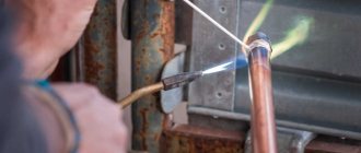
Applications of gas welding
Gas welding belongs to the group of fusion welding methods.
A significant technological difference between gas welding and arc welding is smoother and slower heating of the metal. This difference between a welding gas flame and a welding arc, which in some cases is a disadvantage, in others an advantage of a gas flame, determines the main areas of its application: for welding low-carbon, special and tool steels, non-ferrous metals, cast iron, as well as for surfacing work. Due to the versatility, comparative simplicity and portability of the necessary equipment, it is advisable to use gas welding for many types of repair work. The relatively slow heating of metal with a gas flame quickly reduces the productivity of gas welding with increasing metal thickness, and with a thickness of more than 8 ... 10 mm it is usually not economically viable.
With slow heating, a large volume of the base metal adjacent to the weld pool is heated, which, in turn, causes warping of the welded products. This important circumstance makes gas welding technically impractical for such objects as building metal structures, bridges, cars, frames of large machines, etc. Slow heating also causes the metal to remain in a high temperature zone for a long time, which entails overheating, grain coarsening and deterioration mechanical properties of metals. At the same time, slow heating of the metal with a gas flame when repairing cast iron parts reduces the temperature difference, helps remove gases from the metal of the parts and prevents cracking.