The technical process consists of many stages, each of which must be calculated with millimeter accuracy. All this data is difficult to remember or write down briefly, so a welding process map was invented. It allows you to improve the quality of work: the welder will receive complete information about the type of welding, specialists will carefully control the welded joint, and the optimal set of equipment and components will be selected. Accordingly, the number of defects will decrease and the plant will incur less losses. And all this is possible if you have a welding flow chart.
In this article we will tell you what it is, how a technical map for welding work is drawn up, we will give an example, thanks to which you will learn how to quickly and easily read technological maps, and subsequently draw them up.
Definition
What is a technological map for welding work (also known as technical specifications for welding, a welding technological map, or simply a technical map)? In simple words, this is simply an instruction document issued to the welder to perform the work correctly. The technical map can also be used by a quality control specialist. Everything is written down in the technical sheet: from the type of welding to geometric calculations.
Simply put, a technical map is a “collection” of all technological features that need to be taken into account when welding. A properly developed technical map allows you to improve the quality of the welded joint and, in general, make the work of the welder or other specialists more productive and better.
The technological map was invented and implemented not so long ago, namely in the late 80s of the last century. This is due to a major technological breakthrough in the field of welding, when new modern technologies appeared and rare metals became available.
Welding of metal structures and process maps
Metal structures – metal structures is a generally accepted designation for products made of metals and alloys. For example, parts made of profiled metal in mechanical engineering, load-bearing steel frames of buildings in construction.
If at the beginning of the last century parts cast from cast iron were usually used, modern ones are created from steel or light alloys, such as aluminum. Their advantage:
- ease;
- corrosion resistance (galvanized or aluminum alloys);
- ease of production;
- volumetric strength, rigidity;
- decorativeness;
- installation speed.
Welding is one of the most important and widely used methods of joining metal structures. This process is significantly less expensive than screws and rivets and is more reliable than soldering or gluing.
Welded parts acquire durability properties, are reliable, easy to repair and convenient to manufacture.
It is impossible to simultaneously combine welding and riveting procedures in one structure due to different attitudes to loads. Welded structures are preferable to riveted or glued ones due to lower production costs, material savings, greater reliability when creating tight seams, etc.
The disadvantages are caused by the formation of defects in the seams due to the occurrence of internal stresses due to temperature changes and poor-quality welding.
There are many types of joining individual parts by welding. In each specific case, its own type and method are selected, for which a technological map for welding metal structures is drawn up.
Based on the nature of the requirements for the welded product, materials, component geometry, type of weld, and technique are selected.
Welding of metals is regulated according to a number of physical, technical and technological parameters. The physical criterion includes three main classes - mechanical, thermomechanical, arc welding.
For example, manual electric arc welding is a type of electric welding often used in practice, optimal for welding mild and alloy steels, stainless steel, cast iron, and a number of non-ferrous metals. Obviously, any type of arc welding requires its own process map.
Data in the technical map
So, the technological map must indicate general information about the metal that needs to be welded, data on cutting the metal and their cleaning, data on the size of the welds. The heating of the metal, if necessary, and the sequence of formation of welds are also indicated.
It is also indicated what equipment will be used and what components are needed to perform welding. Some craftsmen are confident that equipment and components can be selected based on their experience or thematic magazines, but this is not true. Later we will tell you how to select a set of equipment. Additionally, you need to indicate what type of welding will be used in the work, as well as what parameters need to be set (the value of welding current, voltage, polarity, welding speed, and so on). It also indicates what shape the welded joint will have and what methods will be used to check the quality of the welds.
2.4. Safety precautions when performing welding work
2.4.1. The housings of arc power sources (transformers), welding auxiliary equipment and welded products are grounded before work begins.
2.4.2. Grounding is carried out with a copper wire, one end of which is connected to a special bolt with the inscription “Earth” on the body of the arc power source, and the other end is connected to the grounding bus.
2.4.3. To connect the welding transformer to the network, wall boxes with switches, fuses and clamps are used. The length of the mains power cables should not exceed 10 m.
2.4.4. If it is necessary to extend the power wires, a coupling with a strong insulating mass is used.
2.4.5. The power wires are suspended at a height of 2.5 - 3.5 m, and the wire runs are enclosed in metal pipes.
2.4.6. Welding wires must be used with proper insulation and have a cross-section appropriate for the welding current.
2.4.7. Light filters that are inserted into the inspection hole of a shield, mask or helmet are selected in accordance with GOST 9497-60, depending on the welding current. There are four types of glass filters: E-1 (for currents 30 - 75 A), E-2 (for currents 75 - 200 A), E-3 (for currents 200 - 400 A), 3 - 4 (for currents more than 400 A).
2.4.8. To protect the eyes of workers assisting in welding work, light filters B-1, B-2 and B-3 are used.
2.4.9. Welding work is carried out in overalls made of tarpaulin or thick cloth, in mittens and a hat, while trousers should not be tucked into shoes, pockets should be closed with flaps, and the jacket should not be tucked into trousers.
2.4.10. When welding ceiling, horizontal and vertical seams, canvas sleeves are put on and tied tightly over the sleeves at the hands.
2.4.11. Weld seams are cleaned of slag only after complete cooling and always wearing glasses with plain lenses.
2.4.12. Ventilation devices must ensure air exchange during manual arc welding with electrodes with high-quality coating from 4000 to 6000 m3 per 1 kg of electrode consumption.
2.4.13. At the workplace, the following concentrations of substances in the air are allowed (in mg/m3): manganese and its compounds - 0.3; chromium and its compounds - 0.1; lead and its compounds - 0.001; hydrogen fluoride - 0.5; nitric oxide - 5.0; gasoline, kerosene - 300.0.
The concentration of non-toxic dust more than 10 mg/m3 is not allowed, however, if the quartz content in the dust exceeds 10%, then the concentration of non-toxic dust is allowed only up to 2 mg/m3.
Peculiarities
In large production facilities (for example, if it is an assembly and welding shop), the development of technical maps is carried out by individual specialists, while in small factories this work is often entrusted to welders. However, any worksheet development must begin with a thorough analysis of the metal to be welded. The choice of welding type, components and other parameters depends on the metal. If you analyze the metal correctly from the very beginning, then you will not have any errors. The welding mode is selected according to regulatory documents, and not according to the experience of the welder. This is also important to understand.
Each technological map for welding metal structures must have its own individual number (code), with which it can be found in the archive. This number will also be indicated when developing complete technical documentation and in the characteristics of the welding project. Also, the technical map must bear the signature of the specialist who compiled this punishment.
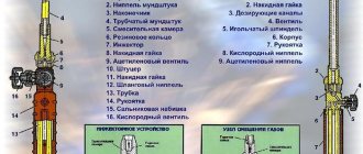
Development of a technological process for manual arc welding
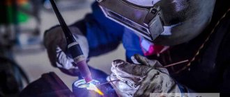
Electric arc welding technology involves heating the parts to be joined by an electric arc, which is usually created between the parts and the electrode.
The temperature of the arc contributes to the melting of the electrode and the surface of the elements being connected, resulting in the formation of a weld.
In this case, the molten slag protrudes on the surface of the weld pool, forming a protective layer that protects the seam from oxidation during cooling.
Process description
Special power supplies that convert the current coming from the electrical network create an arc. When working, they use both alternating and direct current. When using alternating current, the voltage will be reduced by a transformer, while when operating with direct current, the latter is rectified by a special rectifier.
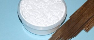
The technological process of electric arc welding involves the use of fusible and non-fusible electrodes. Fusible electrodes melt themselves when creating a seam. When using infusible electrodes, the filler material is melted and fed into the weld pool in the form of special rods.
Shielding gases such as argon, helium, carbon dioxide and mixtures are often supplied to the joint area. They are introduced by the welding head in order to protect the metal of the weld pool from the appearance of oxides.
There are several types of electric arc welding, differing in the main performance parameters:
- process automation: manual, semi-automatic, automated welding;
- methods of protecting the welding zone: submerged arc, argon-arc and gas;
- current supply mode: welding under direct, alternating current, pulse;
- scope of application: connection of elements made of ferrous metal, non-ferrous metal, including aluminum, various pipes.
Electric arc welding device
The electric arc welding process involves a welding machine, parts to be joined, electrodes or filler wire. In almost all cases, special equipment is required to protect the welding area.
The welding machine consists of a powerful step-down transformer, which is a current source. The transformer of a DC welding device is equipped with a rectifier, which is used to convert alternating current coming from the electrical network into direct current.
No less widespread are inverter sources, the operating principle of which is based on the conversion of alternating current supplied from the network to the rectifier into direct current. Through an inverter, direct current is converted into high-frequency alternating current, which is subsequently converted by a step-down transformer.
A standard 50 Hz low frequency alternating current transformer weighs significantly more than high frequency welding current transformers. The converted current is used immediately or after rectification.
In addition to the transformer, arc welding machines are equipped with many auxiliary parts and devices: electrode holders, wires, etc.
Technological process of modern welding
- Welding is used quite widely both for commercial and production purposes, and for performing minor repairs in a private building or in a country house. Equipment and consumables for welding work are offered to consumers in specialized stores and are affordable.
The process of making a welded joint depends on the type of welding. But arc welding has become most widespread. This is what is most often used in everyday life.
But the quality and reliability of the welded joint, as well as the safety of the worker himself, depend on the correct execution of the welding process.
Highlights of electric arc welding technology
Electric arc welding technology involves heating the parts to be joined by an electric arc, which is usually created between the parts and the electrode.
The temperature of the arc contributes to the melting of the electrode and the surface of the elements being connected, resulting in the formation of a weld.
In this case, the molten slag protrudes on the surface of the weld pool, forming a protective layer that protects the seam from oxidation during cooling.
Example of a technological map
Below you can see a sample of filling out the technological map. Now we will take a closer look at everything that is written here, and you will remember (or better yet, write down) what you read.
The sample was taken from the site zibon.ru
So, the first column is “Welding method”. Here, as you might guess, you need to write this type of welding was chosen to perform the work (manual arc, contact, semi-automatic gas, etc.). In our case, we indicated “manual arc welding with coated electrodes.” Next are the numbers “(111)”, this is the welding code. It can be indicated in the technical sheet so as not to write in detail in words.
Here are some of the most common codes:
- 141 - manual argon arc welding with non-consumable electrode
- 131 - mechanized argon arc welding with a consumable electrode
- 135 - mechanized welding with a consumable electrode in an active gas environment
Next is the column “Basic material (brand)”. Here we write the brand of metal that we need to weld. Usually the brand is indicated in the design of the part, from there it can be rewritten into the technical sheet. Additionally, indicate the group of metals. Below is a table with the main groups.
Then comes the column “Name (code) of the NTD”. Here you must indicate which regulatory documents were used in the development of this technological map. The remaining columns are filled in in a similar way, we think everything is logically clear.
In our case, a standard technological map for welding gas pipelines is filled out. But if you need a technical card for other work (for example, for welding steel pipes), then it will be filled out in the same way, the title will just change.
Typical process for welding flanges to pipe ends
A commonly used connection method is flanges. They look like flat parts of different shapes, in which special holes are made for attaching pipes. With their help, pipelines for various purposes and long building structures are assembled. They connect pipes tightly and tightly, providing flexibility in servicing a variety of joints. In addition, they connect the pipe to various equipment and valves.
Relief flanges are often added to a piping system to allow for regular maintenance of the system while it is running. For this purpose, flanges are welded onto the ends of the pipes, which are then bolted together using sealing gaskets. Such additional inserts into the pipeline system allow you to connect various equipment and devices and create additional connection systems.
Flanges can be classified in different ways, for example:
- by connection type;
- by the type of flanges themselves;
- based on temperature values and pressure;
- according to the materials used.
For the manufacture of flanges, carbon, low-alloy, stainless steels and combinations of exotic materials are used.
The use of flanges is quite common. Therefore, a number of standard technical processes have been developed that are used in the procedures for welding flanges to pipes.
Typically, the welding technique is determined by the required amount of play (gap) in the joints created.
- If there is no play, the technique of deep welding the edge of the pipe is used (technique - into a boat).
- Backlash over 1.5 mm is a technical technique of transverse oscillatory movements of the electrode itself, performed at a certain angle to the axial plane of the pipe.
- The backlash is 4-5 mm - fillet weld method.
The flanges are welded on both sides to obtain a reliable connection. This takes into account the type of structure and requirements for fastenings.
Note that underground pipelines do not use flanged connections, as flanges are the most common source of leaks and fires.