7.7.1. Conical pipe thread
Tapered pipe threads in accordance with GOST 6211-81 refer to fastening and sealing threads and are used for connecting pipes in high-pressure pipelines of fuel, oil, water and air systems of machines and machine tools, when increased tightness and reliability are required.
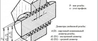
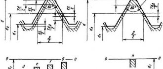
This thread is made on a cone, the generatrices of which make an angle with its axis
=1 O 4724 (taper 1:16). Its profile is similar to the profile of a cylindrical pipe thread (triangle with an apex angle of 55 O with rounded vertices).
In Fig. 7.25 shows the profile of the thread in question, and Fig. 7.26 threaded connection.
55
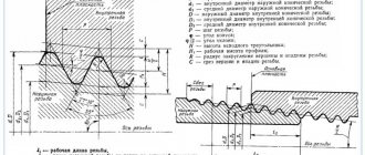
A characteristic feature of tapered threads is that the nominal values of the outer d, inner d1 and middle d2 diameters are taken in the design section - the main plane located at a given distance from the base of the cone.
The position of the main plane of the external thread is determined by the length of the thread l 2 from the end of the pipe to this plane. As already noted (section 7.4.1), if necessary, the main plane of the thread on the rod is shown as a solid thin line. For holes (internal threads), the main plane coincides with the end of the coupling on the side of the larger diameter (Fig. 7.26).
In the drawings, the designation of a conical pipe thread contains the letter R for external threads and R Ñ for internal threads, after which the nominal (conditional) thread diameter in the main plane is indicated in inches, similar to the nominal diameter of a cylindrical pipe thread. This means that the outer and inner diameters of the conical thread in the main plane are equal to the outer and inner diameters of the cylindrical pipe thread according to GOST 6357-81 with the same designation. So from the designation R3/4 it follows that the thread is a conical external pipe thread, the outer diameter of which in the main plane is equal to the outer diameter of the cylindrical pipe thread G3/4
The designation of a conical pipe thread, as well as a cylindrical one, is applied on the shelf of a leader line, the arrow of which rests on the main line of the thread (Fig. 7.27). Working thread length
and the thread length from the end of the pipe to the main plane are standardized and are usually not indicated on the drawing.
The main parameters of conical pipe threads are given in table. 7.5.
25. Holes for cutting metric threads (according to GOST 19257-73)
Hole diameters for cutting metric threads according to GOST 9150-81, GOST 24705-81 with tolerances according to GOST 16093-81 in gray cast iron according to GOST 1412-85, in steel according to GOST 380-94, GOST 1050-88, GOST 4543-71, GOST 10702-78, GOST 5632-72 (except for nickel-based alloys), in aluminum casting alloys according to GOST 1583-93, in copper according to GOST 859-78.
Dimensions and maximum deviations of the diameters of holes of threads with a large pitch
Nominal thread diameter d
Threaded hole diameter with tolerance range
4Н5Н; 5H; 5Н6Н; 6H; 7N
GOST provides holes for threads with a large pitch
HOLES FOR METRIC THREADING (GOST 19257-73)
Hole diameters for cutting metric threads according to GOST 9150-81, GOST 24705-81 with tolerances according to GOST 16093-81 in gray cast iron according to GOST 1412-85, in steel according to GOST 380-2005, GOST 1050-2013, GOST 4543-71, GOST 10702-78, GOST 5632-72 (except for nickel-based alloys), in aluminum casting alloys according to GOST 1583-93, in copper according to GOST 859-78.
Dimensions and maximum deviations of the diameters of holes in threads with a large pitch, mm
Note: GOST provides holes for threads with a large pitch d = 1.0 - 2.2 mm.
Dimensions and maximum deviations of the diameters of fine-pitch thread holes, mm
Note: GOST provides holes for threads with d = 1.0 - 200 mm and for d of the 3rd row. GOST provides a method for determining the diameters of holes for cutting metric threads for materials of high viscosity.
HOLES FOR TAPPING INCH CONICAL THREAD WITH PROFILE ANGLE 60 o (GOST 6111-52)
The dimensions of the holes for threading apply to metals and alloys that do not have high viscosity.
HOLES FOR TAPPING CYLINDRICAL PIPE THREAD (GOST 21348-75)
Diameters of holes for cutting cylindrical pipe threads in accordance with GOST 6357-81 in products made of steel in accordance with GOST 380-2005, GOST 4543-71, GOST 1050-2013 and GOST 5632-72 (except for nickel-based alloys) and copper in accordance with GOST 859-78 .
Note: GOST 21348-75 allows the use of holes of other diameters, obtained on the basis of experimental data, for cutting cylindrical pipe threads.
HOLES FOR TAPERING PIPE THREAD (GOST 21350-75)
The holes are intended for cutting conical pipe threads in accordance with GOST 6211-81 in products made of steel in accordance with GOST 380-2005, GOST 4543-71, GOST 1050-2013, GOST 5632-72 (except for nickel-based alloys) and copper in accordance with GOST 859-78 .
Pipe cylindrical thread. GOST 6357 - 81
Direction: Left
Accuracy class: Class A (increased), Class B (normal)
Why in inches?
The inch size came to us from our Western colleagues, since the requirements of the GOST
and are formulated on the basis of
BSW
(British Standard Whitworth or Whitworth thread). Joseph Whitworth (1803 - 1887), a design engineer and inventor, demonstrated the screw profile of the same name for detachable connections back in 1841 and positioned it as a universal, reliable and convenient standard.
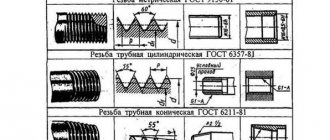
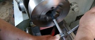
This type of thread is used both in the pipes themselves and in the elements of pipe connections: locknuts, couplings, elbows, tees ( see picture above
). In the profile section we see an isosceles triangle with an angle of 55 degrees and roundings at the tops and bottoms of the contour, which are made for high tightness of the connection.
Threading of threaded connections is carried out on sizes up to 6”. All larger pipes are fixed by welding to ensure a reliable connection and prevent rupture.
Symbol in the international standard
International: G
Japan: PF
UK: BSPP
The letter G and the bore diameter (internal Ø) of the pipe are indicated in inches. The outer diameter of the thread itself is not included in the designation.
Example:
G 1/2
— cylindrical external pipe thread, internal pipe Ø 1/2″". The outer diameter of the pipe will be 20.995 mm, the number of steps over a length of 25.4 mm will be 14.
The accuracy class (A, B) and the direction of turns (LH) can also be indicated.
For example:
G 1 ½ - B
— cylindrical pipe thread, internal Ø 1 ½ inches, accuracy class B.
G1 ½ LH- B
— cylindrical pipe thread, internal Ø 1 ½ inches, accuracy class B, left.
The make-up length is indicated by the last one in mm: G 1 ½ -B-40
.
For internal pipe cylindrical threads, only the Ø of the pipe for which the hole is intended will be indicated.
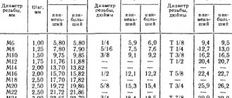
Parallel Pipe Thread Size Chart
| Thread size | Thread pitch, mm | Threads per inch | Thread diameters | |||
How to determine the pitch of an inch thread
I’ll give you a picture from the English-language Internet that clearly demonstrates the technique. Pipe threads are characterized not by the size between the tops of the profile, but by the number of turns per 1 inch along the thread axis. A regular tape measure or ruler can help. Apply it, measure one inch (25.4 mm) and visually count the number of steps.
In the picture with an example ( see above
) threads - from English these are literally “threads of thread”. In this case there are 18 of them. by one inch.
It’s even easier if you have a thread gauge for inch threads lying around in your tool box. It is very convenient to take measurements, but it must be remembered that inch threads may differ in the apex angle of 55° and 60°.
Hole diameter for metric thread: size table according to GOST
Despite the fact that cutting internal threads is not a complex technological operation, there are some features of preparation for this procedure. Thus, it is necessary to accurately determine the dimensions of the preparation hole for threading, and also select the right tool, for which special tables of drill diameters for threads are used. For each type of thread, it is necessary to use the appropriate tool and calculate the diameter of the preparation hole.
The thread diameter and through hole must comply with the standards, otherwise the grooves will come out too small and the threaded connection will be unreliable
Homemade tap for aluminum alloys
To create internal threads in brass or light alloy parts, you can use homemade tools and drills from a regular set. Calibrated steel wire will do. Using a die, an external thread is cut on it, after which the workpiece is hardened. After hardening, it is necessary to release the part to the color of ripe straw. The cutting edges are sharpened using a whetstone or sharpener, after first clamping the part into a collet chuck.
Video on how internal threads are cut:
To cut an internal thread on a part, you must first drill a hole. Its size is not equal to the thread diameter, but should be slightly smaller. You can find the diameter of the drill for the thread in a special table, but to do this you also need to know the type of thread.
Types and parameters of thread
The parameters by which threads are divided into different types are:
- units of diameter (metric, inch, etc.);
- number of thread starts (one-, two- or three-thread);
- the shape in which the profile elements are made (triangular, rectangular, round, trapezoidal);
- direction of rise of turns (right or left);
- location on the product (external or internal);
- surface shape (cylindrical or conical);
- purpose (fastening, fastening and sealing, chassis).
Metric thread parameters
Depending on the above parameters, the following types of thread are distinguished:
- cylindrical, which is designated by the letters MJ;
- metric and conical, designated M and MK respectively;
- pipe, designated by the letters G and R;
- with a round profile, named after Edison and marked with the letter E;
- trapezoidal, designated Tr;
- round, used for installation of sanitary fittings, – Kr;
- thrust and thrust reinforced, marked as S and S45, respectively;
- inch thread, which can also be cylindrical and conical - BSW, UTS, NPT;
- used to connect pipes installed in oil wells.
Thread types according to GOST
Types of thread
They differ in their main characteristics:
- diameter calculation system (inch, metric, others);
- number of passes (two-, three- or single-pass);
- profile shape (rectangular, trapezoidal, triangular, round);
- direction of rotation of the screw (left or right);
- placement on the part (internal or external);
- shape of the part (cone or cylinder);
- purpose (running, fastening and sealing or fastening).
According to the listed characteristics, the following types are distinguished:
- cylindrical (MJ);
- metric and conical (M, MK);
- pipe (G, R);
- Edison round (E);
- trapezoidal (Tr);
- round for plumbing fasteners (Kp);
- persistent (S, S45);
- inch, including cylindrical and conical (BSW, UTS, NPT);
- oil range.
Application of the tap
Before you start threading, you need to determine the diameter of the preparation hole and drill it. To facilitate this task, a corresponding GOST was developed, which contains tables that allow you to accurately determine the diameter of the threaded hole. This information makes it easy to select the drill size.
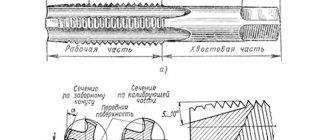
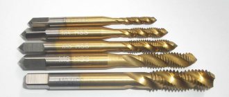
To cut metric threads on the inner walls of a hole made with a drill, a tap is used - a screw-shaped tool with cutting grooves, made in the form of a rod, which can have a cylindrical or conical shape. On its side surface there are special grooves located along its axis and dividing the working part into separate segments, which are called combs. The sharp edges of the combs are precisely the working surfaces of the tap.
Tap: design and parameters
In order for the turns of the internal thread to be clean and neat, and for its geometric parameters to correspond to the required values, it must be cut gradually, by gradually removing thin layers of metal from the surface being treated. That is why for this purpose they use either taps, the working part of which is divided along the length into sections with different geometric parameters, or sets of such tools. Single taps, the working part of which has the same geometric parameters along its entire length, are needed in cases where it is necessary to restore the parameters of an existing thread.
The minimum set with which you can sufficiently perform machining of threaded holes is a set consisting of two taps - rough and finishing. The first one cuts a thin layer of metal from the walls of the hole for cutting metric threads and forms a shallow groove on them, the second one not only deepens the formed groove, but also cleans it.
Types of thread taps and their differences
Minimum set of taps
Combination two-pass taps or sets consisting of two tools are used for tapping small diameter holes (up to 3 mm). To machine holes for larger metric threads, you must use a combination three-pass tool or a set of three taps.
To manipulate the tap, a special device is used - a wrench. The main parameter of such devices, which can have different designs, is the size of the mounting hole, which must exactly match the size of the tool shank.
Some types of tap drivers
When using a set of three taps that differ both in their design and geometric parameters, the sequence of their use must be strictly observed. They can be distinguished from each other both by special marks applied to the shanks and by design features.
- The tap, with which the hole for cutting metric threads is processed first, has the smallest diameter among all the tools in the set and cutting teeth, the upper part of which is heavily cut off.
- The second tap has a shorter fence and longer combs. Its working diameter is intermediate between the diameters of the other tools in the set.
- The third tap, with which the hole for cutting metric threads is processed last, is characterized by full ridges of cutting teeth and a diameter that must exactly match the size of the thread being formed.
Set of three taps
Taps are used primarily for cutting metric threads. Much less often than metric ones, taps designed for processing the internal walls of pipes are used. In accordance with their purpose, they are called pipe, and they can be distinguished by the letter G present in their markings.
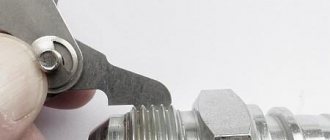
How to cut correctly
Threads can be applied to almost any metals and their alloys - steel, copper, aluminum, cast iron, bronze, brass, etc. It is not recommended to do it on hot iron - it is too hard, it will crumble during operation and it will not be possible to achieve high-quality turns, which means the connection will be unreliable.
Tool for the job
Preparation
You need to work on clean metal - remove rust, sand and other contaminants. Then the place where the thread will be applied must be lubricated (except for cast iron and bronze - they must be worked “dry”). There is a special emulsion for lubrication, but if it is not there, you can use soaked soap. You can also use other lubricants:
You can often hear advice to use machine or mineral oil or even lard when cutting threads. They work well, but experts say that it is better not to do this - the chips will stick to the viscous substance, which will lead to rapid wear of the tap or die.
Slicing process
When cutting external threads, the die is placed strictly perpendicular to the surface of the pipe or rod. During operation, it should not wiggle, otherwise the turns will turn out uneven and the connection will be ugly and unreliable. The first turns are especially important. How they “lay down” determines whether the connection will then be skewed.
By applying the internal thread, the part is fixed motionless. If it is a small piece, you can clamp it in a vice. If the plate is large, ensure its immobility using available methods, for example, by fixing it with bars. M
The tap is inserted into the hole so that its axis is parallel to the axis of the hole. With little effort, little by little, they begin to twist in the given direction. As soon as you feel that the resistance has increased, unscrew the tap back and clear it of chips. After cleaning, the process continues.
Photo cutting process
When cutting a thread in a blind hole, its depth should be slightly greater than required - this excess should include the tip of the tap. If this is structurally impossible, the tip of the tap is cut off. At the same time, it is not suitable for further use, but there is no other way out.
In order for the turns to be of high quality, two taps or dies are used - rough and finishing. The first pass is done as a rough pass, the second as a finishing pass. There are also combined devices for applying threads. They allow you to do everything in one pass.
Another practical tip: to prevent chips from getting into the working area, when cutting, make one full turn clockwise, then half a turn counterclockwise. After this, return the tool to the place where you stopped and make one revolution again. Continue this way until the required length.
Internal thread cutting technology
As mentioned above, before starting work, you need to drill a hole, the diameter of which must exactly fit a thread of a certain size. It should be borne in mind: if the diameters of the holes intended for cutting metric threads are chosen incorrectly, this can lead not only to poor quality execution, but also to breakage of the tap.
Considering the fact that the tap, when forming threaded grooves, not only cuts the metal, but also pushes it, the diameter of the drill for making threads should be slightly smaller than its nominal diameter. For example, a drill for making M3 threads should have a diameter of 2.5 mm, for M4 - 3.3 mm, for M5 you should choose a drill with a diameter of 4.2 mm, for M6 threads - 5 mm, M8 - 6.7 mm, M10 - 8.5 mm, and for M12 - 10.2.
Table 1. Main diameters of holes for metric threads
Table 2. Diameters of holes for inch threads
All diameters of drills for GOST threads are given in special tables. Such tables indicate the diameters of drills for making threads with both standard and reduced pitches, but it should be borne in mind that holes of different diameters are drilled for these purposes. In addition, if threads are cut in products made of brittle metals (such as cast iron), the diameter of the thread drill obtained from the table must be reduced by one tenth of a millimeter.
You can familiarize yourself with the provisions of GOST regulating the cutting of metric threads by downloading the document in pdf format from the link below.
The diameters of drills for metric threads can be calculated independently. From the diameter of the thread that needs to be cut, it is necessary to subtract the value of its pitch. The thread pitch itself, the size of which is used when performing such calculations, can be found out from special correspondence tables. In order to determine what diameter the hole needs to be made using a drill if a three-start tap is used for threading, you must use the following formula:
To = Dm x 0.8, where:
Do is the diameter of the hole that must be made using a drill,
Dm is the diameter of the tap that will be used to process the drilled element.
Scheme of cutting internal threads with a tap
The drivers into which the threaded tap is inserted can have a simple design or be equipped with a ratchet. You should work with such devices with tools fixed in them very carefully. To obtain high-quality and clean threads, rotating the tap clockwise, performed half a turn, must be alternated with turning it one-fourth of a turn against the thread.
The thread will be cut much easier if you use a lubricant during this procedure. The role of such a lubricant when cutting threads in steel products can be played by drying oil, and when processing aluminum alloys - alcohol, turpentine or kerosene. If such technical fluids are not at hand, then ordinary machine oil can be used to lubricate the tap and the thread being cut (however, it has less effect than the substances listed above).
Cutting process
Before you start cutting, you should use drills to make a hole in the workpiece. The diameter of the drill hole must match the internal thread size. When the size of the hole made with drills is chosen incorrectly, the tool can break or the grooves will turn out to be of poor quality.
During cutting, part of the metal does not fall out with chips, but is pressed along the working surfaces of the tap, forming a groove profile on the workpiece. Taking this feature into account, the size of the drill used to make the hole for the thread is selected slightly smaller than the nominal diameter of the future thread.
For example, when cutting M5 (groove diameter is 5 mm), you should choose a drill for a 4.2 mm hole. To cut M4, the diameter of the drill must be 3.3 millimeters, and before working with an M6 tap, a hole is first made with a 5 mm drill. This indicator is calculated taking into account the thread pitch. The pitch can be calculated mathematically, but in practice they resort to correspondence tables, where for an M5 tap the pitch is 0.8, for M4 this figure is 0.7, for M6 - 1. We subtract the pitch index from the diameter and get the required diameter of the drill. When working with brittle metals, such as cast iron, the drill diameter should be reduced by 0.1 mm compared to the size recommended in the table.
The formula for calculating the hole diameter when working with three-pass taps:
Up=Dm * 0.8
;
here: Dm is the diameter of the tap.
| Type | Diameter | Step |
| M1 | 0,75 | 0,25 |
| M1,2 | 0,95 | 0,25 |
| 1,4 | 1,1 | 0,3 |
| 1,7 | 1,3 | 0,36 |
| 2,6 | 1,6 | 0,4 |
| 2,8 | 1,9 | 0,4 |
| M3 | 2,1 | 0,46 |
| M3 | 2,5 | 0,5 |
| M4 | 3,3 | 0,7 |
| M5 | 4,1 | 0,8 |
| M6 | 4,9 | 1 |
| M8 | 6,7 | 1,25 |
| M10 | 8,4 | 1,5 |
Table 1. Correspondence between thread diameters and preparation hole
Before starting work, the tap is inserted into a square shank - a knob. The collars can be regular or ratchet. The carving is done carefully, the first pass is made with a No. 1 tap to the end. Particular attention must be paid to the direction of movement: only clockwise, and some effort must be applied. It is done like this: 1/2 turns along the stroke alternate with 1/4 turns against the screw stroke to destroy the chips.
| Thread in inches | External D, mm | Diameter, mm | Pitch, mm |
| 1\8″ | 2,095 | 0,74 | 1,058 |
| 1\4″ | 6,35 | 4,72 | 1,27 |
| 3\16″ | 4,762 | 3,47 | 1,058 |
| 5\16″ | 7,938 | 6,13 | 1,411 |
| 7\16″ | 11,112 | 8,79 | 1,814 |
| 3\8″ | 9,525 | 7,49 | 1,588 |
Table 2. Hole diameters for inch threads
A couple drops of lubricant will make working on blind threaded holes much easier. Although machine oil is sometimes used as a lubricant, drying oil is optimal for working with steel. With aluminum alloys, it is preferable to use kerosene, alcohol or turpentine. Technical oil can also be used, but with less effect.
Threaded hole diameter: size table according to GOST and calculation
The strength of fastening the parts to each other is ensured by screwing the external thread carrier into the internal thread of the second product. It is important that their parameters are maintained in accordance with the standards, then such a connection will not be damaged during operation and will ensure the necessary tightness. Therefore, there are standards for the execution of carvings and its individual elements.
Before cutting, a hole is made inside the part for the thread, the diameter of which should not exceed its internal diameter. This is done using metal drills, the dimensions of which are given in the reference tables.
Hole parameters
The following thread parameters are distinguished:
- diameters (internal, external, etc.);
- profile shape, height and angle;
- step and entry;
- others.
The condition for connecting parts to each other is the complete coincidence of the external and internal threads. If any of them are not performed in accordance with the requirements, the fastening will be unreliable.
The fastening can be bolted or stud, which, in addition to the main parts, includes nuts and washers. Before joining, holes are formed in the parts to be fastened, and then cutting is carried out.
To perform it with maximum accuracy, you should first form a hole by drilling, equal to the size of the internal diameter, that is, formed by the tops of the protrusions.
When performing a through design, the diameter of the hole must be 5-10% larger than the size of the bolt or stud, then the following condition is met:
where d is the nominal diameter of the bolt or stud, mm.
To determine the hole size of the second part, the calculation is carried out as follows: the pitch value (P) is subtracted from the value of the nominal diameter (d) - the resulting result is the desired value:
The calculation results are clearly demonstrated by the table of threaded hole diameters, compiled according to GOST 19257-73, for sizes 1-1.8 mm with small and main pitches.
An important parameter is the drilling depth, which is calculated from the sum of the following indicators:
- screw-in depth;
- reserve of external thread of the screwed-in part;
- her undercut;
- chamfers.
In this case, the last 3 parameters are for reference, and the first is calculated through the coefficients for taking into account the material of the product, which are equal for products from:
- steel, brass, bronze, titanium – 1;
- gray and ductile cast iron – 1.25;
- light alloys – 2.
Metric tapered thread. GOST 25229 - 82
Parameter unit: mm
Produced on surfaces with a taper of 1:16
Used when connecting pipelines. The angle at the top of the turn is 60°. The main plane is shifted relative to the end ( see figure above
).
Symbol
The letters MK are followed by an indication of the diameter in the main plane and the thread pitch in mm: MK 30x2
Metric Tapered Thread Size Chart
| Thread diameter d for row | Step P | Thread diameter in the main plane | ||||||
| 1 | 2 | d = D | d2=D2 | d1=D1 | l | l1 | l2 | |
| 6 | — | 1 | 6,000 | 5,350 | 4,917 | 8 | 2,5 | 3 |
| 8 | — | 8,000 | 7,350 | 6,917 | ||||
| 10 | — | 10,000 | 9,350 | 8,917 | ||||
| 12 | — | 1,5 | 12,000 | 11,026 | 10,376 | 11 | 3,5 | 4 |
| — | 14 | 14,000 | 13,026 | 12,376 | ||||
| 16 | — | 16,000 | 15,026 | 14,376 | ||||
| — | 18 | 18,000 | 17,026 | 16,376 | ||||
| 20 | — | 20,000 | 19,026 | 18,376 | ||||
| — | 22 | 22,000 | 21,026 | 20,376 | ||||
| 24 | — | 24,000 | 23,026 | 22,376 | ||||
| — | 27 | 2 | 27,000 | 25,701 | 24,835 | 16 | 5 | 6 |
| 30 | — | 30,000 | 28,701 | 27,835 | ||||
| — | 33 | 33,000 | 31,701 | 30,835 | ||||
| 36 | — | 36,000 | 34,701 | 33,835 | ||||
Types of carving
According to the measurement system, threads are divided into metric, expressed in millimeters, and inch, measured in corresponding units. Both of these types can be made in either cylindrical or conical shapes.
They can have profiles of various shapes: triangular, trapezoidal, round; divided according to application: for fasteners, plumbing elements, pipes and others.
The diameters of the preparation holes for threading depend on its type: metric, inch or pipe - this is standardized by the relevant documents.
Holes in pipe connections, expressed in inches, are specified in GOST 21348-75 for cylindrical shapes and GOST 21350-75 for conical shapes. The data is valid when using copper and nickel-free steel alloys. The cutting is carried out inside the auxiliary parts into which the pipes will be screwed - slates, clamps and others.
GOST 19257-73 shows the diameters of holes for cutting metric threads, where the tables show the size ranges of nominal diameters and pitches, as well as the parameters of holes for metric threads, taking into account the values of maximum deviations.
Thread types according to GOST
The data given in the GOST 19257-73 table confirms the calculation given above, in which the parameters of holes for metric types are calculated from the nominal diameter and pitch.
GOST 6111-52 standardizes the diameters of holes for inch tapered threads. The document indicates two diameters with a taper and one without a taper, as well as drilling depths; all values, except the nominal value, are expressed in millimeters.
Main settings
- diameter (D);
- pitch (P) - the distance from one turn to another.
They are determined by GOST 1973257-73. A large step is considered normal, but it corresponds to several smaller ones. A small pitch is used when applying to thin-walled products (pipes with a thin wall). They also make a small turn if the applied thread is a way to adjust any parameters. Also, a small step between turns is made to increase the tightness of the connection and to overcome the phenomenon of self-unscrewing of the part. In other cases, a standard (large) step is cut.
There are many types of threads, since each has its own formation characteristics; the diameter of the hole for the thread is different in each case. All of them are prescribed in GOST standards, but most often they use triangular metric and conical metric threads. We will talk about them further.
We usually see triangular threads on bolts and other similar fasteners, conical threads on most plumbing products that require a detachable connection.
Adaptations
Manual or automatic cutting methods provide results in various classes of accuracy and roughness. Thus, the main tool remains a tap, which is a rod with cutting edges.
- manual, for metric (M1-M68), inch - ¼-2 ʺ, pipe - 1/8-2 ʺ;
- machine-manual - attachments for drilling and other machines, used for the same sizes as manual ones;
- nuts, which allow you to cut a through version for thin parts, with nominal sizes of 2-33 mm.
- For cutting metric threads, use a set of rods - taps:
- rough, having an elongated intake part, consisting of 6-8 turns, and marked with one mark at the base of the shank;
- medium - with a fence of average length of 3.5-5 turns, and markings in the form of two marks;
- the finishing part has a fence of only 2-3 turns, without marks.
Tolerance control of metric thread placement
When cutting manually, if the pitch exceeds 3 mm, then use 3 taps. If the product pitch is less than 3 mm, two are enough: roughing and finishing.
Taps used for small metric threads (M1-M6) have 3 grooves that carry chips and a reinforced shank. The design of the others has 4 grooves, and the shank is through.
The diameters of all three rods for metric threads increase from rough to finish. The last threaded rod must have a diameter equal to its nominal diameter.
The taps are attached to special devices - a tool holder (if it is small) or a crank. They are used to screw the cutting rod into the hole.
Preparing holes for cutting is carried out using drills, countersinks and lathes. It is formed by drilling, and by countersinking and boring it is increased in width and improves the quality of the surface. The fixtures are used for cylindrical and conical shapes.
A drill is a metal rod consisting of a cylindrical shank and a helical cutting edge. Their main geometric parameters include:
- the helical lift angle is usually 27°;
- point angle, which can be 118° or 135°.
Drills are rolled, dark blued, and shiny - ground.
Countersinks for cylindrical shapes are called counterbores. They are metal rods with two cutters twisted into a spiral and a fixed guide pin to insert the countersink into the cavity.
Cutting technique
Using a hand tap, cutting can be carried out following the following steps:
- drill an opening for a thread of the appropriate diameter and depth;
- countersink it;
- secure the tap in the holder or driver;
- align it perpendicular to the working cavity in which cutting will be carried out;
- screw the tap with light pressure clockwise into the hole prepared in advance for threading;
- Turn the tap back every half turn to cut off the chips.
To cool and lubricate surfaces during the cutting process, it is important to use lubricants: machine oil, drying oil, kerosene and the like. Incorrectly selected lubricant can lead to poor cutting results.
Selecting drill size
The diameter of the drill for a hole for a metric thread is also determined by formula (2), taking into account its main parameters.
It is worth noting that when cutting in ductile materials, such as steel or brass, the turns increase, so it is necessary to choose a larger drill diameter for the thread than for brittle materials, such as cast iron or bronze.
In practice, drill sizes are usually slightly smaller than the required hole. Thus, Table 2 shows the ratio of the nominal and outer thread diameters, the pitch, the diameters of the hole and the drill for cutting metric threads.
Table 2. The relationship between the main parameters of metric threads with normal pitch and the diameters of the hole and drill
Tables for selecting the diameter of a drill for threading
When making an internal thread, a hole is pre-drilled for it. It is not equal to the diameter of the thread, since when cutting, part of the material is not removed in the form of chips, but is squeezed out, increasing the size of the protrusions. Therefore, before application, it is necessary to select the diameter of the drill bit for the thread. This can be done using tables. They are available for every type of thread, but here are the most popular ones - metric, inch, pipe.
| Metric thread | Inch thread | Pipe thread | |||||
| Thread diameter, inches | Thread pitch, mm | Drill diameter, mm | Thread diameter, inches | Thread pitch, mm | Drill diameter, mm | Thread diameter, inches | Threaded hole diameter, mm |
| M1 | 0.25 | 0,75 | 3/16 | 1.058 | 3.6 | 1/8 | 8,8 |
| M1.4 | 0,3 | 1,1 | 1/4 | 1.270 | 5.0 | 1/4 | 11,7 |
| M1.7 | 0,35 | 1,3 | 5/16 | 1.411 | 6.4 | 3/8 | 15,2 |
| M2 | 0,4 | 1,6 | 3/8 | 1.588 | 7.8 | 1/2 | 18,6 |
| M2.6 | 0,4 | 2,2 | 7/16 | 1.814 | 9.2 | 3/4 | 24,3 |
| M3 | 0,5 | 2,5 | 1/2 | 2,117 | 10,4 | 1 | 30,5 |
| M3.5 | 0,6 | 2,8 | 9/16 | 2,117 | 11,8 | — | — |
| M4 | 0,7 | 3,3 | 5/8 | 2,309 | 13,3 | 11/4 | 39,2 |
| M5 | 0,8 | 4,2 | 3/4 | 2,540 | 16,3 | 13/8 | 41,6 |
| M6 | 1,0 | 5,0 | 7/8 | 2,822 | 19,1 | 11/2 | 45,1 |
| M8 | 1,25 | 6,75 | 1 | 3,175 | 21,3 | — | — |
| M10 | 1,5 | 8,5 | 11/8 | 3,629 | 24,6 | — | — |
| M12 | 1,75 | 10,25 | 11/4 | 3,629 | 27,6 | — | — |
| M14 | 2,0 | 11,5 | 13/8 | 4,233 | 30,1 | — | — |
| M16 | 2,0 | 13,5 | — | — | — | — | — |
| M18 | 2,5 | 15,25 | 11/2 | 4,33 | 33,2 | — | — |
| M20 | 2,5 | 17,25 | 15/8 | 6,080 | 35,2 | — | — |
| M22 | 2,6 | 19 | 13/4 | 5,080 | 34,0 | — | — |
| M24 | 3,0 | 20,5 | 17/8 | 5,644 | 41,1 | — | — |
Once again, please note that the diameter of the drill bit for the thread is given for large (standard thread).