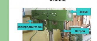
Lathe device for a home workshop
These mini-machines differ from metalworking lathes in that they do not require a cooling system.
The power indicator of the woodworking unit is also less. This is due to the physical characteristics of the material that is processed on such equipment. Wood blanks lend themselves much better to grinding or turning, so working with them does not require much power. Units for home workshops take into account the possibility of regulating the rotation speed. The main structural elements of this device, which belong to the functional part, are: a cartridge and cutters.
The main function of the chuck for a wood lathe is to ensure reliable fixation of the workpiece, which has a certain cross-sectional index. In turn, the cutter is used for manual work on a mini-machine that does not have a support. As a rule, cutting units are used for the manufacture of various household utensils (for example, handles for shovels), as well as for making simple blanks for painting.
The cartridge is fixed to the front assembly (headstock), which includes the gearbox. This important structural element of the machine is distinguished by a cam device.
Machines for home use, as a rule, take into account the possibility of regulating the rotation speed
Thanks to the presence of a cam mechanism, it becomes possible to securely fix the workpiece in the chuck, and this is very important for normal operation. The chuck is massive and is responsible for accurately changing the position of the workpiece during processing
This device also rotates the processed wooden product.
The rear assembly includes a cone-shaped hole. It is necessary to install the center, the function of which is to fix the wooden blank. Often such a thrust unit is sold separately. Buying a tailstock for a lathe is not difficult, as there are many offers for its sale on the Internet.
Mini-machines are able to cope with a basic set of technical operations. Let's look at what can be done on wood lathes:
- Lathe tailstock
- turning;
- pruning;
- grinding;
- making grooves;
- drilling holes;
- carving.
Tabletop machines are distinguished by their small dimensions, but this does not affect its functionality
Advantages and disadvantages
The advantages include the following characteristics:
- mobility;
- durability of components and parts;
- perfect security system;
- availability of all the equipment necessary to complete a full course on working on a lathe.
This installation is suitable for studying, but professionals generally do not use it, because:
- the installed three-phase motor makes it difficult to connect in rooms where a household electrical network is installed;
- the maximum length of the workpiece is 500 mm, this greatly limits the capabilities of the unit;
- the two-speed mode does not allow performing a number of high-precision work.
Electrical diagram
- » onclick=»window.open(this.href,» win2 return false >Print
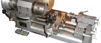
Construction of a wood lathe
Making cylindrical parts by hand is labor-intensive and time-consuming work. And it is difficult to get a good quality product. You can make a cylindrical part
on
a lathe
.
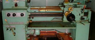
It processes wood blanks by turning. The main parts of a lathe are a bed, a headstock with an electric motor, a tailstock and a tool rest.
Lathe for wood processing STD-120M and its parts:1
– base;
2
– electric motor;
3
– bed;
4
– belt drive guard (casing);
5
– magnetic starter;
6
– front headstock;
7
– spindle;
8
– tool rest;
9
– tailstock.
In the headstock
(see figure)
a spindle
-
a shaft that receives rotation from an electric motor using a belt drive, as well as bearings.
1
-
headstock body; 2 — belt pulley; 3
—
washer with locking screw
;
4
,
7
-
shaped covers
;
5
-
thrust ring
;
6
-
spindle
;
8
-
special nut
.
Screw-cutting lathe TV 16: design and operation
Spindle end
has a thread,
special devices are screwed onto it for fastening the left end of the workpiece
.
Depending on the size of the workpiece, different devices are used: a trident
(see Fig.
a
),
a faceplate
(see Fig.
b
),
a cartridge
(see Fig.
c
).
Workpieces of small diameter and length up to 150 mm are fixed in a chuck.
Before this, the end of the workpiece is slightly beveled into a cone, clamped in a workbench clamp and driven into the chuck with a mallet. For more reliable fastening, a screw is screwed into the workpiece through the side hole.
Long workpieces are fixed at one end in a trident
. To do this, make a recess in the center of the end of the workpiece with an awl (or drill a hole with a diameter of 4-5 mm to a depth of 5-9 mm). After this, a cut is made through the center of the workpiece with a hacksaw with fine teeth to a depth of 3-5 mm. In the center of the other end, make a recess with an awl.
Short workpieces of large diameter are mounted in a faceplate
, screwing the workpiece with screws.
Tailstock
(see figure)
serves as a support for the right end of long blanks
.
The tailstock is brought to the workpiece along the frame guides and secured motionless with a bolt and nut. Finally, the end of the workpiece is pressed with a special part - the center. It is moved by rotating the flywheel
and secured with a clamp.
1
- frame;
2
— center (Morse cone);
3
- quill;
4
— clamp handle;
5
- hole for lubrication;
6
— quill nut;
7
— quill screw;
8
- threaded bushing;
9
- flywheel;
10
— screw for fastening to the frame;
11
- cracker.
The support for the cutting tool is a tool rest
(see figure). It can move both along and across the frame, and is secured by turning the handle.
- Using a lathe 1d601
The tool rest is installed in such a way that its upper supporting part is 2-3 mm above the level of the center line of the machine and is no more than 3 mm away from the workpiece. To check the gap, the workpiece is turned by hand one or two turns.
The transmission of motion in mechanisms and machines is shown by symbols on kinematic diagrams
.They depict details that are directly involved in the transmission of motion. For clarity, contours of other parts are often given. The kinematic diagram of a lathe is shown in the figure.
You can turn on the lathe and work on it only with the permission of the teacher. Do not place tools and foreign objects on the machine bed. The belt drive parts of the machine must be protected. Do not lean on parts of the lathe. Immediately report any malfunctions in the machine and electrical wiring to the teacher.
Modern factories are equipped with lathes (more complex and productive than those you will work on in a training workshop). They are serviced by woodworking machine operators
. In addition to mastering all the techniques of turning on a machine, they must know the properties of wood, the structure of machines, be able to read drawings and diagrams, sharpen a tool, and set up a machine
Working on machines requires accuracy and precision, attentiveness and caution, coordination of hand movements
The installation is designed for processing short wooden pieces. The small size of the unit allows it to be located in small spaces. The equipment is quite simple, so it is called a school machine. The unit is especially appreciated where high precision is not required. Critical points of the working area are protected. Directional illumination of the workpiece, an improved electrical circuit, and a waste removal installation distinguish this equipment from its analogues.
Types of cutters for wood lathe
Cutters are elements that are used to remove certain volumes of wood. All of them, from a constructive point of view, are similar to each other and consist of two main elements: a cutting part and a locking part (rectangular or square).
The cutting edge can be represented by one or more surfaces. This element differs in its shape and width, which are selected depending on the nature of the technological operation. The main criterion by which cutters are classified is their location relative to the wooden block. They can be in two positions:
- radial;
- tangential
In the first case, the cutter is used to remove large volumes of wood. To do this, it is placed perpendicularly. In turn, the tangential position is used to remove a small amount of wood from the surface of the workpiece. This allows you to make complex patterns on it.
Chisels for wood lathes are also classified according to their purpose. Today there are many cutters that differ in their design and are used to perform various technological operations. Let's look at the most common of them:
Reyer. A product that is used for rough processing of workpieces. The peculiarity of this cutter is its blade, which resembles a semicircle in shape.
When choosing cutters for woodworking, give preference to trusted manufacturers
Meisel. This element is necessary for finishing. Its use allows you to give the wooden block its final look. Meisel is a plate with an oblique blade, which is sharpened on both sides at the same angle.
Scraper. A cutter of this type is needed to level the surface of blanks, which have a cylindrical shape.
Comb. Used for applying carvings to the surface of a wooden workpiece.
Hook. This type of cutter is used to organize cavities inside workpieces.
You can buy cutters for wood lathes at markets, flea markets, in a specialized store, or order online. As a rule, these products are sold in sets.
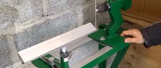
Examples of basic work with hand tools in woodworking: A - rough turning; B, C - first pass; G - cutting off chips; D - trimming the part
Equipment
For a novice carpenter, the device is equipped with a full set of tools (Maisels, Reiers). The device itself consists of an electric motor, a control unit, a frame, as well as other holding and protective mechanisms. Let's look at the most important of these nodes in more detail.
Front headstock of the unit
The front headstock of the machine is used to secure and hold the part while the engine is running. It is a shaped body cast from cast iron, in which two holes for radial spherical bearings are bored coaxially.
Rear element
The back element or tailstock serves as a support for securing long workpieces, drill chucks, drills themselves, as well as other woodworking tools.
The tailstock consists of a body with a built-in quill that slides along the bed to adjust the length. The required length is fixed using a special bolt that holds the rear element in the desired position.
Main and removable devices
On the STD-120m you can install removable devices to perform various tasks:
- chuck for securing short workpieces at the end;
- center-fork, for installing and processing long parts in the center;
- faceplate.
To secure the workpiece to the outer surface, use the following devices:
- Cup cartridge. It consists of a cylindrical cavity on one side, and a shank for mounting a spindle on the other side.
- Vise chuck. Needed for processing workpieces in the shape of a quadrangle. To work, the workpiece is clamped in a chuck vice and pressed with a screw.
Both types of chucks can have screw threads instead of conical shanks for installation on the outside of the spindle.
Electrical equipment and technical parameters
The STD-120m lathe is equipped with a three-phase asynchronous motor operating on 380V alternating current. The maximum electricity consumption by the motor is 0.4 kW.
The device is controlled by a button block, on which there is a speed switch button, as well as a button to turn off the device.
Inside the control box there is a 380/24 V lighting transformer.
Important!
Do not attempt to repair or disassemble the asynchronous motor of the device yourself. To repair this unit, call a trusted electrical technician.
Main and removable devices
The STD-120M wood cutting machine is equipped with several basic elements, namely:
- A trident used to secure the workpiece. It has a cone shape at one end, identical to the spindle. The second edge of the element is made in the form of a fork with three prongs. The workpiece is fixed by placing the intended groove directly into the trident, after which the second end is clamped into the tailstock quill.
- A cup chuck, which is a part that has a cylindrical interior on one side and a conical shank on the other, which is used for installation in the spindle part of the headstock. The round side of the workpiece is tightly placed in the cartridge cavity or clamped with bolts.
- If the workpiece has a multifaceted shape, a vice chuck is used.
- In addition, the STD-120M lathe can be equipped with chucks with three or four jaws. They serve to secure parts to the outer part. Self-centering elements have independent cam movement, allowing for faster processing and greater efficiency.
Technical characteristics and parameters
The total weight of the machine with electric motor, protective casing and tool rest is 100 kg. In the working position, with the shield lowered, the dimensions are 1250 x 575 x 550 mm. An electric motor with a power consumption of 400 W is powered by a 380 V network.
Separate control of the engine and local lighting is carried out via a keypad and is limited to the On/Off positions. The height of the centers is 120 mm. The maximum diameter of the workpiece is 190 mm, and the length is 500 mm.
The maximum shaft rotation speed is set before turning on the machine and is determined by one of two belt positions on the pulleys, 1100 and 2150 rpm, respectively. The local lighting lamp operates on a constant voltage of 24 V.
A folding transparent screen with a canvas skirt is designed to protect the operator. Under the longitudinal guides there is a chip storage and also a window for cleaning with active blowing. Regular lubrication of the moving parts of the machine is carried out every 500 working hours.
Purpose and recommendations for use
The lathe can be used for light wood turning work:
- internal turning and drilling of parts;
- trimming or trimming;
- turning cylindrical figures;
- processing flat surfaces on the faceplate.
The STD-120m is quite unpretentious in operation. However, to reduce the risk of injury, as well as the correct operation of the unit, it is worth following the operating requirements:
- The lathe is installed on a flat and level surface at a height of 500-600 mm from the floor. This could be a workbench or desktop.
- The safety screen on the machine must be lowered during operation. If the machine does not have a chip collection unit, it is necessary to lower the canvas skirt.
- Machine speeds are switched only after the spindle has completely stopped.
- Under no circumstances should you try to move the machine or adjust the workpiece while the motor is running.
- It is strictly prohibited to remove chips, adjust or measure the workpiece, as well as lubricate the device components while the machine is operating! The above actions can only be done after the spindle has completely stopped.
Important!
Install the machine on a flat floor surface, without distortions. To reduce risks and unforeseen situations, place a rubber backing or a sheet of plywood between the legs of the table or workbench and the floor.
It is also worth following the rules of machine maintenance to increase its service life:
- It is necessary to regularly clear chips from the work area. Also, after finishing work, you need to clean the protective screen from fine dust and sawdust.
- After finishing the work, put all the tools in the storage box. Apply neutral lubricant to unpainted areas. For example, on a guide frame.
- Check the condition of the lubrication on all components at least once a year or after 500 hours of operation.
- Upon completion of work, unplug the power cord from the outlet and loosen the tension on the V-belt.
Operational Features
The wood lathe STD-120M does not belong to the category of professional equipment; its main purpose is to familiarize students with the basics of a turner’s work. It is subject to increased security measures.
To ensure the stability of the processing tool, it is better to make the base steel or concrete. Its height must be at least 60 centimeters.
In addition, some operational features should be taken into account:
- The wood workpiece must be free of cracks and knots.
- The humidity of the part is allowed no higher than 20 percent.
- Large elements must be processed at minimum speed.
- At least once a year or after five hundred hours of operation, you need to lubricate moving elements and check the equipment for deformation and malfunctions.
Before performing repair work or servicing the machine, you should study its structure and also read the operating manual in detail.
Tailstock of lathe STD-120M
The tailstock of the STD-120 machine serves as a support when processing long workpieces, supporting them with the rear center, and for securing a drill chuck, the drills themselves and other tools in its quill when processing holes. The tailstock STD-120 consists of a body with a quill, which slides along the guides of the bed. The tailstock of the STD-120 machine is fixed to the bed guides.
On one side, the quill has a hole bored to a Morse taper, into which the rear center, chucks or drills with a shank with the same taper are inserted. On the other side, a sleeve with internal thread is pressed in. The quill moves freely in the hole in the upper part of the housing. The quill is prevented from rotating around its axis by a set screw that fits into a groove on the outer surface of the quill.
A quill (feed) screw is paired with the threaded bushing, at one end of which a flywheel is mounted on a key and secured with a nut. Rotating with the flywheel, the quill screw moves the quill through a threaded bushing.
The quill is secured in the desired position using the clamp handle. The tailstock is secured with a nut on the frame with a block and a bolt, for screwing which a combination wrench is included. To lubricate the quill and screw, there are oil-conducting holes in the body of the headstock and quill.
V-belt drive
A two-stage pulley is rigidly attached to the electric motor shaft of the STD-120 lathe, which, using a V-belt, transmits rotation to a two-stage pulley mounted on the spindle of the STD-120 machine. By moving the belt from one stage to another, you can change the spindle speed. The V-belt drive of the STD-120 machine is covered by a metal fence, the opening cover of which is interlocked through a limit switch with an electric motor. When it opens, the electric motor is switched off and the spindle of the STD-120 machine stops.
Rear element
This part of the STD-120M machine provides support when servicing long products, as well as securing the chuck, drills themselves and other tools. The rear element of the device consists of a frame and a quill sliding along the guide grooves of the body.
On one side of the movable sleeve there is a hole adjusted to a cone, where a back stop, a cartridge or a drill with a corresponding end stop is placed. A bushing with an internal thread is inserted from the opposite side by pressing. The set screw ensures easy movement of the quill and prevents it from rotating around its own axis.
The torque redistribution element is combined with a threaded bushing, on one edge of which a flywheel is installed, secured with a nut. The quill is secured in the required position using a clamping handle. The tailstock is fixed using a nut, a block (washer) and a bolt. To lubricate the working elements, special holes are provided in the housing.
Arrangement
The STD-120M machine has some device features, namely:
- The speed of rotation is changed by throwing the belt onto certain grooves of the shafts.
- The control unit with buttons is located on the headstock, which provides the most convenient access to the controls during operation.
- Spindle-type attachments can be changed; they are included in the standard equipment set.
- The work area is protected by additional curtains with transparent windows.
- You can remove chips and other debris using the optionally connected cleaning unit.
The accuracy of the operations can be increased by special lighting, the operation of which is controlled by a step-down transformer. The electrically interlocking belt drive design with switch increases operational safety.
Purpose
The STD-120M school lathe is used for light wood processing by central interaction, using a faceplate and chuck, as well as for basic drilling. Its functionality includes the following:
- Sharpening of cylindrical and profile rotating elements.
- Ability to trim, round and cut workpieces at different angles.
- Perform turning along the marked profile.
- Drilling.
- Processing of flat diameter surfaces in decorative and profile terms using a faceplate.
The STD-120M is brought into operation by starting the electric power plant. The motor is located on the left side of the unit. Torque is transmitted through belt interaction. This process is facilitated by a pair of pulleys: the first is mounted on the motor shaft, the second is mounted on the headstock spindle.
Design
One of the attractive features is that the device is quite simple. The lathe installation diagram is shown in the figure.
The machine consists of:
- three-phase electric motor,
- headstock and tailstock,
- button block,
- assistant,
- spindle,
- lantern,
- belt drive,
- center-forks.
And:
- enclosing screen,
- protective casing,
- beds,
- flywheel,
- quill,
- carriages,
- handles and locking nuts,
- sinuses for discharging wood processing waste,
- other small parts.
Headstock device
The unit is a shaped cast iron casting. Two radial bearings are inserted into the bored holes of its body. The spindle rests on them, which is the connecting shaft between the drive pulley and the faceplate. The pulley transmits rotation from the engine to the faceplate, chuck or other device through the spindle.
At the bottom of the housing there is a rotation control unit. A lantern is installed on top.
Tailstock
This is a support for the workpiece. The bed moves along the platform on runners. The device is secured with a bolt fastening. On top there is a quill - a holder for a conical tip, the sharp end of which enters the wooden blank on one side.
Front headstock of the unit
This unit of the STD-120M turning unit is used for mounting and fixing the workpiece with the subsequent transmission of rotational moments to it. This element consists of a solid cast iron body of an open type. It has a pair of holes bored along its axes, which serve to accommodate radial, spherically made bearings.
The working spindle is a shaped shaft made of steel, which has a thread on the right for mounting a chuck, washer and other special attachments that fix and process the workpiece. At the left end there is a two-stage pulley-type drive, activated by a V-belt drive from an electric motor. On both sides of the headstock there are hatches with felt padding. The spindle is started and stopped using a control unit located on the housing.