Device characteristics
The technical characteristics of the multifunctional lathe 1d601 are as follows:
- accuracy according to GOST – class N;
- the maximum diameter of the workpieces is 12.5 cm;
- the length of the blanks is 18 cm;
- main shaft cone standard – Morse KM2;
- number of speeds – 3, permissible speed – 2800;
- weight of the structure – 30 kg;
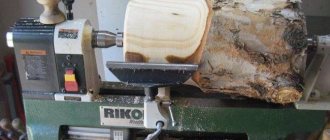
The 1d601 desktop lathe is primarily used to create single workpieces for household use. For mass production, it is better to purchase a more bulky and industrial model. The device's dials regulate the depth of stroke of the main cutter, which improves accuracy.
Even the outdated 1d601 lathe, the technical characteristics of which remained at the original level, is not inferior in the efficiency of processing workpieces to some modern installations.
Main technical characteristics of the machine 1D601
| Parameter name | 1D601 | 16T02P | 16Т02А |
| Basic machine parameters | |||
| Accuracy class | N | P | A |
| The largest diameter of the workpiece above the bed, mm | 125 | 125 | 125 |
| The largest diameter of the workpiece above the support, mm | 75 | 75 | 75 |
| Height of centers above flat bed guides, mm | 68 | 68 | |
| Maximum length of the workpiece at centers (RMC), mm | 180 | 250 | 250 |
| Maximum length of the workpiece processed without reinstalling the support, mm | 55 | 65 | 65 |
| Maximum cutter height, mm | 8 x 8 | 8 x 8 | |
| Spindle | |||
| Diameter of through hole in spindle, mm | 10,2 | 10,2 | 10,2 |
| Morse taper spindle | Morse 2 | Morse 0 | Morse 0 |
| Number of speed steps for direct spindle rotation | 3 | 6 | 6 |
| Spindle direct rotation frequency, rpm | 700, 1400, 2800 | 400, 630, 1000, 1250, 2500, 4000 | 400, 630, 1000, 1250, 2500, 4000 |
| Caliper. Submissions | |||
| Longitudinal movement of the caliper | Manual | Manual | Manual |
| Maximum lateral movement of the caliper, mm | 60 | 60 | |
| Transverse movement of the caliper by one division of the dial, mm | 0,05 | 0,01 | 0,01 |
| Maximum movement of the upper (incisor) slide, mm | 65 | 65 | |
| Movement of the cutting slide by one division of the dial, mm | 0,05 | 0,01 | 0,01 |
| Angle of rotation of the upper carriage of the caliper, degrees | ±30 | ±30 | |
| Tailstock | |||
| Morse taper tailstock | Morse 1 | Morse 0 | Morse 0 |
| Maximum movement of the quill, mm | 35 | 40 | 40 |
| Electrical equipment | |||
| Main drive electric motor, kW (rpm) | 0,180 (1400) | 0,25 | 0,25 |
| Dimensions and weight of the machine | |||
| Machine dimensions (length width height), mm | 680 x 200 x 220 | 695 x 520 x 300 | 695 x 520 x 300 |
| Machine weight, kg | 30 | 35 | 35 |
Useful links on the topic. Additional Information
Catalog reference tabletop lathes
Data sheets for benchtop lathes and equipment
Buy a catalog, directory, database: Price list of information publications
This is interesting: Pipe cutting machine 1N983 - technical characteristics, passport, device
Advantages and scope
The 1D601 benchtop lathe has a huge number of complaints regarding the quality of components and assemblies used in metal production, the accuracy of surface mating and the geometry of the main dimensional chains. But at the same time, it is still extremely popular and continues to be used by tens of thousands of enterprises, organizations and citizens throughout the post-Soviet space. Its main advantages still remain:
- Weight and dimensions. 1D601 weighs only 30 kg and has the following dimensions: length - 68 cm, width - 20 cm and height - 22 cm. Some craftsmen equip their turning workshops with such a machine on the balconies of city apartments.
- Ease of operation, unpretentiousness and reliability. 1D601 has four lubrication points for routine maintenance, is powered from the home electrical network, and due to the simplicity and “oaky” design, it is almost impossible to break it (unless extreme processing modes are used).
- Mass availability and maintainability. There are quite a lot of mechanisms and assemblies from old equipment of this type offered on the secondary market. Home craftsmen repair it practically on their knees, managing to adapt components and assemblies from similar machines of other types to it.
- Price. Currently, there are quite a few different versions of 1D601 offered on the secondary market - both in worn-out condition, as well as “overhauled” and modernized. Their price, depending on condition and completeness, ranges from 8 to 25 thousand rubles.
Tabletop lathes 1D601 are used by numerous home craftsmen for whom turning is a hobby.
They are used in small production and repair enterprises, circles of model designers, and in pilot production at scientific institutions and laboratories. Quite a few of these machines are still used in the workshops of schools and especially vocational schools.
Online auction Antiquity
Internet auction Starina
Everything from the ruble!
- Why register?
- How to buy?
- How to sell?
- FAQ
Basket
Sell
Registration Recent
- Lots
Sections Searches Favorites
- Lots
Sections Searches
- Recent
- Lots
- Sections
- Search
Favorites
Lots Sections Searches Buying Bargaining now I bought Didn't buy Subscribe to new lots Requests for lots from sellers Sellers' offers Selling Transactions Completed auctions Top up account Demand Seller settings My store Activation Settings
Bargaining now I bought Subscription to new lots Requests for lots from sellers Sellers' offers Selling Sell On sale Transactions Completed auctions Top up your account Demand Seller settings
| Welcome to the online auction Antiquity Use the topic sections on the left, the search bar at the top, or the tags on the right to search for items. Want to know more?
Recommended lots: (show all) 20 rub. 10 rubles 2022 OLONETS Tambovskaya and 25 rubles Wolf Zabivaka 3rd issue 20 rub. 10 kopecks 1991 M! Weather! Excellent! State Emergency Committee 60 RUR Rwanda 2010, Space, Space Research, Copernicus, Galileo, block, GAS. 500 RUR Set of postcards. Soviet art issue 1. Painting 1917 1932. Moscow 1963. Circulation 25 thousand. 310 RUR 2018 Israel 2601 Music. Ensemble Gevatron RUR 183 O. Sopotsinsky. Art of the Western European Middle Ages. M.: Art 1964. 80 pp., i. (B1212) 280 RUR 10 cents 1923 s USA Mercury dime silver 90% 75 RUR Notgeld Germany Berlin (berlin) 50 Pfennig 1921. variant 19 pankow. n 218120 325 RUR Panama 1985 mnh** Painting Art 500 RUR Dish China china Roses Gilding Relief Porcelain Antique h2.5 d27 Excellent Vintage 300 RUR 3 kopecks 1924, xf- 60 RUR Postcard painting by Kramskoy. Mermaids. Scenery. 1990. 21929 | |
| RUR 449.00 | 16 seconds |
| 79.00 rub. | 30 seconds |
| 420.00 rub. | 55 seconds |
| 30.00 rub. | 56 seconds |
| RUR 449.00 | 58 seconds |
| View more → |
Entrance:
| For you and your site: |
| • Auction on your website! |
| • Open your own store |
| • Affiliate program |
| Frequently asked questions and support |
| Terms of Use | Sell | Registration | Open your auction | Affiliate program | Profile | Help All rights reserved 1999 - 2022. Old man |
Lathe 1d601: technical characteristics, advantages
A device that allows processing of workpieces made of metal, wood or plastic, which can be performed in centers or in a chuck. Advantages: lightweight and easy to use.
The reliable and compact lathe 1d601 is most suitable for domestic use and creating single samples of parts made of wood, metal or plastic. Despite its modest overall dimensions, this model is capable of processing with accuracy class H, and this quality is not lost even after many years of use. This is largely due to the combination of a reliable kinetic scheme and the traditional layout of structural units.
More information about the device and equipment specifications
Next, we will look at what main parts the 1d601 table lathe consists of and briefly describe each of them.
Let's start with the bed. It has prismatic-type guides along which the spare parts move (a T-shaped groove is used to fix it in the required position) and a support. The PB is fastened through a pair of holes. Guides of this type perform one very important function: thanks to them, the 3B quill and the spindle axis coincide exactly, ensuring the required processing quality.
The headstock is an element that ensures movement (or rather, rotation) of the workpiece. The spindle located here is supported by a pair of angular contact ball bearings. At the end of the spindle head is a three-stage pulley that transmits motion through a belt drive to the spindle. The source of this “movement” is the electric power unit. By the way, this three-stage pulley allows you to set 3 different speeds on the spindle (revolutions per minute):
Drilling holes, supporting particularly long workpieces, as well as turning parts on centers would be unthinkable without such an element as the tailstock. Its quill moves freely along the frame thanks to the movement of the flywheel and an M6x1 screw. The 3B cone is made for the drill chuck mandrel and has a Morse KM1 specification. Clamping of its quill is possible using a special handle.
The caliper is also secured to the frame using nuts and bolts. Changing the position of its slide is carried out thanks to a (mechanical) screw-nut type transmission. On the upper slide there are grooves in the shape of the letter “T”, with the help of which the cutter head is fixed. To process cone-shaped parts, it is necessary to rotate the support (its rotating part) to the required angle. This is not difficult to do.
The single-phase DVE-071-4 is installed as an electric drive on the indicated equipment model. A power of 0.18 kilowatts is enough to perform the necessary production operations. It is noteworthy that you can change the tension of the transmission (belt) during a short stop of the engine. So, in particular, the nuts are loosened first. Then the synthetic belt is tensioned to the desired position. The last step is to tighten the nuts. That's it, the equipment is ready for use again.
The main specifications of the described model are presented in the table below:
| Maximum diameter of workpiece above the caliper above the plane of the bed | mm mm | 75 125 |
| l blanks (largest) | mm | 180 |
| Quill movement max | mm | 35 |
| main drive | kW | 0.18 |
| Spindle through hole (D) | mm | 10.2 |
| Caliper movement (longitudinal) | type | only manually |
| Device weight | kg | 30 |
| dimensions | mm | 680 by 200 by 220 |
Paying attention to the last two positions of the table, it becomes obvious that the device can be easily placed not only in a workshop or garage, but even in a city apartment. No comments yet
No comments yet
Modernization of lathe 1D601
A year ago, I didn’t even know that small tabletop lathes existed. I was eager to buy at least some kind of machine. I looked at all the advertisements for the sale of drains of this type. Last December, an idiot's dream came true. An advertisement appeared on AVITO about the sale of the 1D601 machine, right next door, that is, it’s not a pig in a poke, but you can look and try and there is no risk of money scams. In general, there was no limit to my happiness, I lost my temper and was immediately at the seller’s. But when I saw this machine, I was very surprised, it was very small (before that I had only seen something like this in a photo), but a long-suffering desire overshadowed my mind, the price was also to the maximum. And I bought it. When I brought it home, I was depressed and sad - the money was wasted. I read all the forums and YouTube about fine-tuning such machines and started working.
The plans were big, so to begin with I decided to make a tool holder for normal cutters that can be used to work. The fact is that it’s impossible to attach at least some decent tool holding to what’s available. What can be done if a 10/10 cutter with a 2mm spacer lies on a small longitudinal one, and it hits exactly in the center. In general, this is the kind of tool holder I made to begin with.
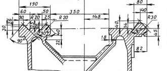
The cartridge was like a torn gun barrel; it had to be sharpened. And then off we went. First, the drawings. I measured all the details, drew it all, and then made it. It turned out with
the first time, there was no need to redo anything. I’ll make a reservation right away that the dimensions are accurate, but this is for a specific machine, I think for others they may be slightly different.
Another very important detail. From the front I installed a support plate.
What is it for? The fact is that the guides of the machine are very narrow, and the bearings only work to lift the caliper. When processing parts larger than 35 mm in diameter, the cutting part of the cutter almost extends beyond the prism and the rigidity of the support drops significantly, and the machine begins to crush. The plate rests on the corner, thereby, as it were, expanding the guides by a couple of centimeters. These couple of centimeters are very significant for such a machine, so it is now possible to process larger parts, and the rigidity of the support has increased significantly.
I abandoned the small longitudinal feed, and in its place I made a platform and a tool holder, all welded, since there is no milling cutter even in the immediate area. Now you can install cutters up to 15 mm.
If desired (if you need to sharpen a cone), a small longitudinal feed is set in its place. To do this, a hole is drilled in the upper part of the groove into which fastening screws for the small longitudinal or tool holder platform can be inserted and removed. The screws are inserted and removed through the top - no need to disassemble the caliper.
Then the cross feed stopped working (large gaps).
The idea came to do everything on radial bearings. I have plenty of small radial bearings, the whole thing in the washer is the backlash. The same design applies to longitudinal feed. Handwheels without keys or cotter pins. just on the thread and secured with a nut - this is quite enough. The feed nut is made of caprolon (it does not give any backlash)
All this was done on the same machine. I had to tinker with the longitudinal one. I redid it several times. At first, everything seems to be satisfactory, but in the process, mistakes are revealed. The problem is that there is a large backlash in the feed, since the structure was not rigid enough. Well, just recently I brought everything to mind (as far as possible). There are practically no backlashes, but it looks like this.
The question may arise: why not place the nut directly under the caliper, is this a more rigid design? But then the travel of the caliper towards the tailstock will be reduced, so this is the only way.
But in general it looks like this. Some minor details may vary in the photo as some items were slightly altered during the process.
moment. The design is completely mine. The pulley on the spindle was increased to 90 mm, it is plastic. Now I don't need a set of pulleys to adjust the speed. Minimum rpm 250, max 1500.
Plus, I changed the bearing in the headstock and the drive belt. The belt was poly-V-ribbed, I ground it down and it turned out flat.
Got a tool
In general, the machine turned out to be normal, enough for my needs.
Design Features
In terms of its capabilities, the 1D601 machine does not differ from industrial-type equipment. The design also consists of the main components and assemblies characteristic of a universal lathe. But at the same time, there are design features that are unique to this unit and determine its technical characteristics.
Device bed
This is a casting with prismatic guides. On the left side of the frame there are holes for attaching the spindle head. Prismatic guides allow the spindle axis to coincide with the rear quill axis. There is a vertical guide for installing the caliper.
Headstock
It is attached to the left side of the frame and held on by two studs. Inside the headstock there is a spindle mounted on support bearings with a through hole for feeding bars. On the left is a three-stage pulley, which is connected to the electric motor pulley by a flat belt. A chuck with 3 jaws is installed on the right side of the headstock. The diameter of the cartridge is 8 cm.
Caliper
It consists of two main elements - a longitudinal slide and a transverse one with a tool holder installed on them. At the very beginning of processing, the support is secured to the required position using a nut and bolt.
Tailstock
The thrust head is located on the guides on the right side of the machine. This node is moved to the required positions manually. The movement of the quill is also carried out manually using a special handwheel.
Table and drive
The machine is installed on the table and secured with two studs, washers and nuts. The drive uses a single-phase electric motor with a power of 180 kW and a three-stage pulley. By moving the engine, belt tension is controlled.
The device of a desktop lathe 1d601
Construction diagram of the machine 1d601
The basis for the machine is a bed, supported by two pedestals and cast from durable cast iron. On top of it there are prismatic profile guides for the caliper. Between them there is a T-shaped groove for the tailstock. On the left side of the frame, the headstock is secured using two holes for studs. The machine is installed on the table and fixed on it using threaded holes (M10) in the cabinets. Thanks to the ground guides of the bed, the coaxiality of the spindle (in the headstock) and the quill (in the tailstock) is achieved.
The spindle is equipped with two support units. A pair of angular contact bearings is installed in the front, and a radial ball bearing is installed in the rear. The spindle is made hollow to allow processing of round and other shaped bars. All these parts are assembled inside the headstock housing and tightened with a nut.
The headstock housing has a pair of covers with gaskets made of oil-resistant material to prevent lubricating oil leakage. A stepped (three stages) belt pulley is attached to the spindle on the console. It transmits torque from the electric drive through a flat belt. The front end of the spindle, emerging from the headstock body, is completed with a thread (M27 * 3) with a collar, and a grinding wheel mandrel is pressed onto the rear end through a cone. The 3-jaw chuck is screwed onto the spindle thread until it stops and clamped with screws.
The machine support has a cross-shaped design and is fixed with a bolt connection to the frame. All movements of its upper/lower slide are provided by lead screws with nuts only in manual mode. The slides move along the guides of their bases (their profile is “dovetail”). A tool holder is mounted to the upper slide using a pair of T-shaped slots. To machine cones, the caliper has the ability to rotate to the required angle. To do this, you need to release the crackers by turning the eccentric clamps, turn the caliper (graduation value 4o) and tighten the eccentrics again. And reinstalling the bar on the caliper will allow you to grind parts of different diameters.
The design of the tailstock allows you to drill longitudinal holes, press long workpieces in a chuck with a rotating center, or sharpen parts in centers. Its retractable part, the quill, is moved by a screw driven by a flywheel. The quill has a Morse taper (No. 1) for a mandrel (drill chuck) or thrust center. Fixing the position of the quill in the tailstock body, as well as the headstock itself on the frame, is done with clamping handles that are similar in design.
The tension of the drive belt is restored by moving the electric motor along the grooves in its base, followed by tightening the fastening nuts. Changes in spindle rotation speed are achieved by transferring a flat belt from one pulley diameter to another.
Purpose of the turning device
The main advantage of this machine is its convenience and ease. The unit is perfect for use in school workshops or home production. The structural elements are very reliable. This allows for processing with the highest level of accuracy. The machine can be used for decades.
In addition to school and home workshops, the 1d601 table lathe can be used in traveling technical schools, as well as laboratories. All lovers of this type of turning work can use the unit in the garage. It is also indispensable for designers and modelers, who make every detail for their models by hand using special equipment. The development of imagination and working skills will help make this device an ideal assistant for organizing leisure time for both schoolchildren and adults.
Lathe 1D601
The 1d601 lathe is a unit suitable for performing basic operations on processing materials by cutting. It is suitable for mobile or industrial workshops of schools, colleges, laboratories and clubs to develop work and leisure skills. Such equipment is convenient to operate at home, garage cooperatives, and young technicians’ stations, using it for single production of parts.
This tabletop machine will take up limited space on your desktop. Its energy consumption during operation is very small. A knowledgeable user is quite capable of performing routine maintenance and simple repairs independently. This compact turning equipment can rather be classified as a school or hobby class machine. The 1d601 machine is well made, has a long service life and is capable of efficiently performing a limited set of operations. Its accuracy is normal.
Advice: Do not ignore or fail to comply with the frequency of maintenance of the machine. Timely compliance with the requirements of the operating instructions will extend its life and ensure the quality of work.
Headstock
The body of the desktop machine is closed on both sides with covers. In addition, they are equipped with gaskets that are designed to prevent oil leakage from the housing.
At the end of the spindle, a three-stage pulley is cantilevered, transmitting rotation from an electric motor. This happens using a synthetic flat belt. The front cone is made of a Morse taper KM 2, while the rear body, intended for mandrel sharpening, is installed at an angle of 40 degrees. The landing diameter is 10 A. Using 1d601, you can process the thinnest twigs, the diameter of which does not reach 10 mm.
Headstock
General information about the TSH-1.10 sharpening machine
The machines are equipped with an electric motor M1, operating in three-phase switching mode, an input automatic machine QF1, an electromagnetic starter KM1, a start button SA1, a start button SA1, a stop button SA2. All equipment is placed in a niche of the stand (stand) on the panels. The supply wires are inserted through the hole in the rear wall of the stand (stand) to the water switch QF1/
Description of operation in three-phase mode (figure).
By turning on the input switch QF1, voltage is supplied to the machine. Pressing the SA1 “Start” button turns on the magnetic starter KM1 and supplies voltage to the windings of the three-phase electric motor. The electric motor is stopped by pressing the SA2 “STOP” button. In this case, the magnetic starter KM1 is turned off.
Information about the manufacturer of the table lathe 1D601
The manufacturer of the 1D601 table lathe is the Kirovakan Precision Machine Tools Plant in Kirovkan (today Vanadzor), Armenia.
The main purpose of the machine was to teach turning in schools, vocational schools, technical schools, and are widely used in laboratories, training and repair shops.
Currently, production of the machines has been discontinued.
Machine tools produced by the Kirovakan Precision Machine Tools Plant
- 1D601
- table lathe Ø 125 - 1E604
- high-precision screw-cutting lathe Ø 200 - 16B05P
- high-precision screw-cutting lathe Ø 250 - 16T02P
- high-precision table lathe Ø 125 - 16T04a
- especially high precision lathe Ø 200 x 350 - 16U03P
- high-precision screw-cutting lathe Ø 160 - 16U04P
- high-precision screw-cutting lathe Ø 200 - 1600
— high-precision table lathe Ø 100 - 1603
— high-precision screw-cutting lathe Ø 160 - S193n
- high-precision table lathe Ø 200 - S-193
- high-precision table lathe Ø 200 - S-155
,
SA-155
- tabletop drilling machine Ø 3
1D601 Table lathe. Passport, diagrams, characteristics, description
The manufacturer of the 1D601 table lathe is the Kirovakan Precision Machine Tools Plant in Kirovkan (today Vanadzor), Armenia.
The main purpose of the machine was to teach turning in schools, vocational schools, technical schools, and are widely used in laboratories, training and repair shops.
Currently, production of the machines has been discontinued.
Machine tools produced by the Kirovakan Precision Machine Tools Plant
The tabletop lathe model 1D601 is intended for various turning operations on wood, plastics and metal, performed in the chuck and in centers.
Area of application: school and camping workshops, technical schools, laboratories, as well as at home for lovers of turning and model designers, which will help use leisure time to develop labor skills and ingenuity.
The desktop lathe 1D601 allows you to perform the following types of work:
- Grooving and boring of cylindrical and conical surfaces
- End trimming
- segment
- Drilling and a number of other works
Manufacturer: Kirovakan Precision Machine Tools Plant, Kirovakan (today Vanadzor).
The 1D601 lathe was produced in 1971-1976 according to GOST 7599-72.
- The largest diameter of a Disk-type workpiece processed above the bed is Ø 125 mm;
- The largest turning diameter of a workpiece of the Shaft type above the upper part of the support is Ø 75 mm;
- Distance between centers - 180 mm;
- The longest turning length with one support installation is 55 mm;
- Power supply - 220 V;
- The spindle drive electric motor is single-phase AVE-071-4; 0.180 kW; 1400 rpm;
- The weight of the machine is 30 kg.
Headstock and spindle of lathe 1d601
- Threaded spindle end - M27x3 mm
- The standard diameter of a three-jaw lathe chuck is Ø 80 mm
- The diameter of the through hole in the spindle is Ø 10.2 mm;
- The largest diameter of the processed rod is Ø 10 mm;
- The internal (tool) cone of the spindle is Morse 2;
- Spindle speed - 700, 1400, 2800 rpm;
- Front spindle support - radial ball bearings No. 46205 2 pcs;
- Rear spindle support - radial ball bearing No. 205 1 pc.;
- Bearing lubrication - thick grease CIATIM-201 GOST 6257;
- Spindle braking - no;
The spindle of the 1d601 machine receives 3 rotation speeds from an asynchronous electric motor through a 3-speed pulley.
The front end of the spindle has an M27x3 thread for installing an intermediate flange with a lathe chuck
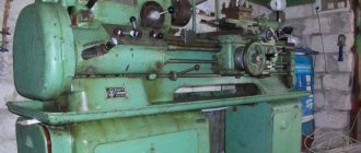
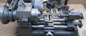
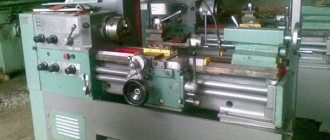
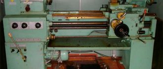
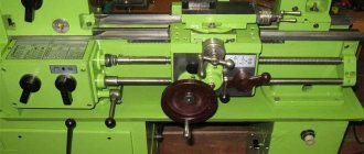
1D601 General view of the lathe
Photo of table lathe 1d601
Photo of table lathe 1d601
Photo of table lathe 1d601
Photo of table lathe 1d601
Photo of table lathe 1d601
1D601 Lathe design
Design of table lathe 1d601
Design of lathe 1D601. View enlarged
The bed (part 0111) is a casting with prismatic guides. On the left side of the frame there are two holes for attaching the headstock, and in the lower plane there are 2 M10 holes for attaching the machine to the table. A T-shaped groove in the frame is used to secure the tailstock in the desired position
The prismatic guides of the frame ensure that the axis of the headstock spindle coincides with the axis of the tailstock quill. The vertical guide (location I) is used to install the caliper.
The headstock (unit 02-00) is attached to the frame guides using 2 studs and nuts (parts 21 and 19). Two radial thrust ball bearings No. 46205 are used as the front support of the spindle. The rear support is a radial ball bearing No. 205. The headstock parts are assembled in the housing (part 0211) and tightened with a nut (part 0216).
Headstock of lathe 1D601
The housing is closed on both sides with lids (parts 0217 and 0218) with sealing rings (parts 0219 and 0220) and gaskets (parts 0222) that prevent lubricating oil from leaking out of the housing.
A 3-speed pulley (part 0212) is installed in a cantilever at the end of the spindle and transmits rotation to the spindle from the electric motor through a synthetic flat belt. The front inner cone of the spindle for the center is made with a Morse taper KM2, and the rear cone for the sharpening device mandrel is made at an angle of 40° with a seat diameter of 10A.
The chuck washer (part 0751) is placed on the front end of the spindle along the spindle thread M27 x 3 until it stops at the spindle collar and is secured with 3 screws (part 22). The headstock spindle has a through hole Ø 10.2, which makes it possible to process bars with a diameter of up to 10 mm.
If necessary, disassembling the headstock should begin by unscrewing the nut (part 0216) clockwise, as viewed from the pulley side. The nut thread is left. Next, the pulley is removed and the spindle is pressed out. Assembly should be done according to Fig. 1.
Lathe support 1D601
The cross support (unit 05-00) is installed and secured using a bolt and nut (parts 0345 and 0354) on the machine bed. The lower and upper slides of the caliper (parts 0311 and 0313) are moved using lead screws (parts 0339 and 0340) and bronze nuts (parts 0351 and 0353) along the dovetail guides of the bases (parts 0312 and 0314).
The threads of the longitudinal and transverse lead screws M6 x 1 make it possible to obtain a division value of 0.05 mm on a relatively small diameter of the dials.
The upper slide (part 0311) has T-shaped slots for attaching the tool holder. To process conical surfaces, it is necessary to set the rotating part of the caliper to the desired angle. To do this, loosen the crackers (part 0338) by turning the eccentrics (part 0335) and turn the upper base at an angle by aligning the marks of the upper base with the scale mark on the lower slide and tighten the crackers again with the eccentrics. The scale division of the lower slide is 4°.
When installing the caliper on the frame, it is necessary to rest the caliper bar (part 0315) against the narrow boss of the frame (place 1 on the frame) and then tighten the nut (part 0354). This ensures parallelism of the longitudinal and perpendicularity of the transverse movements relative to the spindle axis. The bar (part no. 0315) can be rearranged by loosening the fastening of the bar with the handle (part no. 0343). This ensures the ability to process different diameters on the machine.
Tailstock of lathe 1D601
The tailstock is used for machining parts on centers, as a stop when machining long parts in a chuck, and for drilling holes using a drill chuck and drill bits.
The tailstock quill (part 0421) is moved by an M6 X 1 screw (part 0422) from the handwheel (part 0426). The quill cone is made with a Morse taper KM 1 for the center and the mandrel for the drill chuck.
To clamp the quill of the front part of the body (part 0411), there is a cut with a clamping handle (part 0343). The tailstock is secured to the machine bed in the desired position using a cracker (part 0432) and an eccentric with a handle (part 0429). The spring (item 4) under the cracker serves to push out the cracker when rearranging the tailstock.
Table and drive of lathe 1D601
The machine is installed on the table and secured with two studs, washers and nuts (parts 10, 9 and 8). To drive the spindle, a single-phase electric motor of the ABE-071-4 brand with a power of 180 W and a speed of 1400 rpm is used. An electric motor with a 3-speed pulley attached to its shaft (part 0813).
The belt is tensioned by moving the engine. In this case, you need to loosen the nuts, tighten the belt and tighten the nuts again. By transferring the belt from one pulley stage to another, three speeds can be obtained on the spindle: 700, 1400 and 2800 rpm.
1D601 Electrical circuit of a lathe
Electrical circuit of lathe 1d601
Parameter name 1D601 16T02P 16T02A
| Basic machine parameters | |||
| Accuracy class | N | P | A |
| The largest diameter of the workpiece above the bed, mm | 125 | 125 | 125 |
| The largest diameter of the workpiece above the support, mm | 75 | 75 | 75 |
| Height of centers above flat bed guides, mm | 68 | 68 | |
| Maximum length of the workpiece at centers (RMC), mm | 180 | 250 | 250 |
| Maximum length of the workpiece processed without reinstalling the support, mm | 55 | 65 | 65 |
| Maximum cutter height, mm | 8 x 8 | 8 x 8 | |
| Spindle | |||
| Diameter of through hole in spindle, mm | 10,2 | 10,2 | 10,2 |
| Morse taper spindle | Morse 2 | Morse 0 | Morse 0 |
| Number of speed steps for direct spindle rotation | 3 | 6 | 6 |
| Spindle direct rotation frequency, rpm | 700, 1400, 2800 | 400, 630, 1000, 1250, 2500, 4000 | 400, 630, 1000, 1250, 2500, 4000 |
| Caliper. Submissions | |||
| Longitudinal movement of the caliper | Manual | Manual | Manual |
| Maximum lateral movement of the caliper, mm | 60 | 60 | |
| Transverse movement of the caliper by one division of the dial, mm | 0,05 | 0,01 | 0,01 |
| Maximum movement of the upper (incisor) slide, mm | 65 | 65 | |
| Movement of the cutting slide by one division of the dial, mm | 0,05 | 0,01 | 0,01 |
| Angle of rotation of the upper carriage of the caliper, degrees | ±30 | ±30 | |
| Tailstock | |||
| Morse taper tailstock | Morse 1 | Morse 0 | Morse 0 |
| Maximum movement of the quill, mm | 35 | 40 | 40 |
| Electrical equipment | |||
| Main drive electric motor, kW (rpm) | 0,180 (1400) | 0,25 | 0,25 |
| Dimensions and weight of the machine | |||
| Machine dimensions (length width height), mm | 680 x 200 x 220 | 695 x 520 x 300 | 695 x 520 x 300 |
| Machine weight, kg | 30 | 35 | 35 |
Useful links on the topic. Additional Information
Catalog reference tabletop lathes
Data sheets for benchtop lathes and equipment
Directory of woodworking machines
KPO Directory
Buy a catalog, directory, database: Price list of information publications
stanki-katalog.ru
Purpose of the turning device
The main advantage of this machine is its convenience and ease. The unit is perfect for use in school workshops or home production. The structural elements are very reliable. This allows for processing with the highest level of accuracy. The machine can be used for decades.
In addition to school and home workshops, the 1d601 table lathe can be used in traveling technical schools, as well as laboratories. All lovers of this type of turning work can use the unit in the garage. It is also indispensable for designers and modelers, who make every detail for their models by hand using special equipment. The development of imagination and working skills will help make this device an ideal assistant for organizing leisure time for both schoolchildren and adults.
Description and purpose of the unit
The equipment in question easily performs basic work on processing workpieces made of metal, wood and plastic. Basic operations available on this machine:
- boring and turning of cylindrical and conical holes;
- trimming ends;
- cutting a part from a workpiece;
- drilling
The equipment is also suitable for a number of other jobs. Used by turning enthusiasts at home and for developing work skills among young people.
general information
Any model of the 1d601 working machine has no difficulties in operation; after reading the operating instructions, the 1d601 metal lathe is suitable as a training unit for schoolchildren. Unit units are characterized by high reliability, stable operation and simultaneous ease of assembly. Even if complex problems occur, both partial repairs and complex replacement of individual elements are allowed.
Passport 1d601 is distinguished by a lot of indicators that are small in size: weight, overall dimensions, operating speed. The design of the machine is also simplified, but if desired, modernization with mounted additional modules is allowed.
Instructions for use of the unit, passport
Before operation, you must read the operating instructions. Be sure to check whether the machine is grounded. The initial start-up can then be carried out by initially lubricating the machine. The spindle should be started and allowed to idle for 3-4 minutes.
When working on turning equipment, be sure to follow safety rules. The work place at the machine should not be slippery or cluttered, and the master himself should wear safety glasses. Do not use an unsharpened or faulty tool.
The 1D601 tabletop machine has not been produced since 1988. But it is still used in private workshops and many schools. Such equipment can be purchased on the secondary market, in used or modernized condition. With its light weight, great repair capabilities and long service life, this equipment remains in demand among specialists.
Headstock
The body of the desktop machine is closed on both sides with covers. In addition, they are equipped with gaskets that are designed to prevent oil leakage from the housing.
At the end of the spindle, a three-stage pulley is cantilevered, transmitting rotation from an electric motor. This happens using a synthetic flat belt. The front cone is made of a Morse taper KM 2, while the rear body, intended for mandrel sharpening, is installed at an angle of 40 degrees. The landing diameter is 10 A. Using 1d601, you can process the thinnest twigs, the diameter of which does not reach 10 mm.
Headstock
Device bed
A casting with prism-shaped guides is a bed. On the left you can see two holes through which the front assembly is mounted. There are also two holes at the bottom. With their help, the device can be securely fixed on the tabletop. The T-shaped notch ensures that the rear assembly is installed in a pre-selected direction.
You can install the caliper using a vertical guide. The 02-00 unit, called the headstock, is attached with a pair of studs to the bed guides. After assembling the parts, it is necessary to tighten the parts of the structure using a nut.
The body of the desktop machine is closed on both sides with covers. In addition, they are equipped with gaskets that are designed to prevent oil leakage from the housing.
At the end of the spindle, a three-stage pulley is cantilevered, transmitting rotation from an electric motor. This happens using a synthetic flat belt. The front cone is made of a Morse taper KM 2, while the rear body, intended for mandrel sharpening, is installed at an angle of 40 degrees. The landing diameter is 10 A. Using 1d601, you can process the thinnest twigs, the diameter of which does not reach 10 mm.
Lathe design
The 1D601 lathe has a traditional composition and layout of the main components and assemblies. All its mechanisms (except for the electric motor) are mounted on a cast iron frame. On its upper plane there are prismatic guides on which both headstocks and a support are placed, and on the lower plane there are two holes for securely fastening the frame to the table. An electric motor is installed separately from the machine, the rotation of which is transmitted to the spindle via a belt pulley.
Headstock
The headstock is mounted on guides on the left side of the bed, and is attached to it with two studs. A spindle with a through hole for feeding the rod is installed inside the headstock on support bearings. A three-stage pulley is attached to the left end of the spindle, connected to the electric motor pulley by a flat belt, and a three-jaw chuck with a diameter of 80 mm is attached to the right end.
Tailstock
The tailstock is located on guides on the right side of the machine. It moves manually along the guides to the required position and is fixed during processing using an eccentric with a handle located on the back of its body. The movement of the tailstock quill is carried out manually using a handwheel. When turning long parts, a center is inserted into the quill cone, and when drilling and tapping, a drill chuck is inserted.
Caliper
The main structural elements of the 1D601 lathe support are the lower slides that move longitudinally along the bed guides and the upper slides with a tool holder installed transversely to them. Before processing the part, the support is installed in the desired position manually and secured to it using a bolt and nut. Transverse and longitudinal working feeds are carried out by rotating the handwheels, while the maximum stroke length is limited by the size of the slide lead screws (60 mm in the transverse direction and 65 mm in the longitudinal direction). For turning conical surfaces, the upper slide is rotated to the required angle on the scale with an accuracy of 4°.
Table and drive
In accordance with the “Operation Manual”, the 1D601 lathe must be attached to the table using two studs with nuts. Connoisseurs of this turning equipment also offer another “desktop” option: installing and securing the bed on a 10 mm thick steel plate, which increases structural rigidity and reduces vibration.
Rotation of the machine spindle is transmitted from a single-phase electric motor with a three-stage pulley. To change the pulley stage, you need to unlock the motor (loose the fastening nut), move it towards the frame, loosen the belt, move it to another stage, and then tighten it by moving the motor back and tighten the fastening nut.
Electrical diagram
The electrical equipment of the 1D601 lathe is not numerous and includes four standard elements:
- electric single-phase asynchronous motor with a power of 180 W;
- motor starting winding capacitor 4 μF 600 V;
- batch switch;
- plug for connecting to the home electrical network.
According to operating conditions, 1D601 must be grounded, therefore there is a grounding screw at the right end of the frame. Users themselves equip the machine with a lighting lamp, and sometimes install high-power motors. The latest modernization is not always safe, since when the cutter bites, a more powerful rotation can damage the caliper or even tear out a piece of the bed (these machines do not have the best metal quality).
Units of lathe 1D601
The basis in the model under consideration is a casting with triangular guides. On its left side there are two mounting holes for mounting the front unit, and two holes at the bottom, through which the unit is fixed to the countertop. The T-shaped notch is designed to install the rear assembly in the selected position. The coincidence of the axis of the main shaft with the axis of the quill is ensured by triangular guides.
The front assembly is installed on the guides using two nuts and studs. The unit housing is sealed with sealed lids, which prevents oil leakage.
The main shaft is mounted on supports - at the front on two thrust bearings and at the rear on a radial bearing. A pulley is installed at the end of the shaft, which transmits the rotation element to the shaft from the engine via a flat belt. A faceplate is installed on the front of the shaft, which is secured with three screws. The main shaft of the front assembly is a hollow pipe, which allows processing blanks with a diameter of up to 1 cm.
The tool holder is attached to the base of the unit with nuts and bolts. The lower and upper carriages move mechanically by means of lead screws and nuts along trapezoidal guides. The perpendicular and axial lead screws are threaded, making it possible to obtain a scale division of 0.05 mm on a small diameter. To install the cutting head, there are T-shaped notches on the upper carriage.
When working with conical surfaces, the rotating part of the tool holder is set to the required angle. To do this, the crackers are loosened by turning the eccentrics, the upper base is rotated so that the base marks line up with the scale of the lower carriage, and the crackers are tightened again.
When fixed to the base, the tool holder bar rests against the narrow boss of the base, and the nut is tightened. The bar is rearranged using a handle, which loosens its fastening, which ensures the processing of workpieces of various diameters.
The rear unit is designed for working with blanks in the centers, drilling holes and holding long workpieces. The quill moves with the help of a screw from the flywheel, and its cone is made to fit the mandrel and the center of the chuck. The front quill is clamped by a handle located in the cut.
The rear assembly is fixed on the base in the required position with a cracker and an eccentric with a handle. The ejection of the cracker during the movement of the rear unit is carried out due to the spring located under it.
The equipment is fixed to the tabletop with washers, studs and nuts. The device operates from a single-phase motor, whose power is 180 W and rotation speed is 1400 rpm. A pulley is installed on the motor shaft.
The belt is tensioned by the movement of the engine, which is carried out by loosening the nuts, tightening the belt and tightening the nuts. By throwing the belt over the pulley steps, three main shaft speeds become available.
Nodal units of the machine
The passport of the 1d601 model lists several components that ensure its functionality. The operating instructions provide detailed rules for working with individual modules. The benchtop turning unit consists of the following main components:
- The small frame makes it easy to transport the device.
- A movable headstock located at the front of the machine.
- Holding support.
- Tailstock of the unit.
- Drive unit.
Additional equipment is considered to be the dials of the 1d601 machine, which are responsible for the precise displacement of the workpiece relative to the main cutter. When working with dials, it is necessary to correctly calculate the required numerical values, since their graduation may differ. To do this, you should check the lathe's passport, where the offset values are clearly stated.
Structural diagram of the machine
Bed model 1d601
The description of the main unit of the turning unit should begin with the small total weight of this structural element. The bed has always burdened the passports of turning machines, which became a stumbling block for many private workshops. Due to its small size and minimal weight among analogues, it is possible to perform filigree processing of small blanks.
The functional purpose is the basis for the movement of the caliper; the tailstock also moves along prismatic-type guides. This form of guides ensures uninterrupted operation of moving elements.
Headstock
This element has average operating weights; engineers did not endow it with functionality, but made it completely ready for performing rotational movements of the workpiece. A serious flaw in the first models of machines of this type was the insufficiently mobile headstock, which seriously impaired the speed of work and the capabilities of this process. Previous models used simple electrical circuits, which also acted as a certain limitation.
Electrical diagram of the machine
More advanced electrical circuits have significantly increased productivity. The details of the electrical equipment are also indicated in the installation passport.
Caliper
Longitudinal feed of 1d601 is carried out by simple displacement of the rotary handles, which is ensured by a movable support. The clamping device is attached to the main frame with bolts and corresponding nuts. Any movement of this part does not reduce the full view of the workpiece.
The purpose of the support is to fix the workpiece and ensure its longitudinal feed to the cutter.
Drive unit
The advantage of the machine’s power unit is considered to be optimal power and the ability to operate at several speeds. There are 3 different speeds depending on the number of revolutions of the workpiece:
- Minimum forward rotation speed – 700 rpm.
- Rotation at speed 2 reaches a speed of 1400.
- Maximum drive performance is 2800 rpm.
In the technical list of characteristics you can familiarize yourself with the kinematic diagram, the exact dimensions of the displacements of the blanks, and modifications of each individual spare part for the installation.
Main technical characteristics of the machine 1D601
| Parameter name | 1D601 | 16T02P | 16Т02А |
| Basic machine parameters | |||
| Accuracy class | N | P | A |
| The largest diameter of the workpiece above the bed, mm | 125 | 125 | 125 |
| The largest diameter of the workpiece above the support, mm | 75 | 75 | 75 |
| Height of centers above flat bed guides, mm | 68 | 68 | |
| Maximum length of the workpiece at centers (RMC), mm | 180 | 250 | 250 |
| Maximum length of the workpiece processed without reinstalling the support, mm | 55 | 65 | 65 |
| Maximum cutter height, mm | 8 x 8 | 8 x 8 | |
| Spindle | |||
| Diameter of through hole in spindle, mm | 10,2 | 10,2 | 10,2 |
| Morse taper spindle | Morse 2 | Morse 0 | Morse 0 |
| Number of speed steps for direct spindle rotation | 3 | 6 | 6 |
| Spindle direct rotation frequency, rpm | 700, 1400, 2800 | 400, 630, 1000, 1250, 2500, 4000 | 400, 630, 1000, 1250, 2500, 4000 |
| Caliper. Submissions | |||
| Longitudinal movement of the caliper | Manual | Manual | Manual |
| Maximum lateral movement of the caliper, mm | 60 | 60 | |
| Transverse movement of the caliper by one division of the dial, mm | 0,05 | 0,01 | 0,01 |
| Maximum movement of the upper (incisor) slide, mm | 65 | 65 | |
| Movement of the cutting slide by one division of the dial, mm | 0,05 | 0,01 | 0,01 |
| Angle of rotation of the upper carriage of the caliper, degrees | ±30 | ±30 | |
| Tailstock | |||
| Morse taper tailstock | Morse 1 | Morse 0 | Morse 0 |
| Maximum movement of the quill, mm | 35 | 40 | 40 |
| Electrical equipment | |||
| Main drive electric motor, kW (rpm) | 0,180 (1400) | 0,25 | 0,25 |
| Dimensions and weight of the machine | |||
| Machine dimensions (length width height), mm | 680 x 200 x 220 | 695 x 520 x 300 | 695 x 520 x 300 |
| Machine weight, kg | 30 | 35 | 35 |
Bibliography:
Tabletop lathe model 1D601. Operating manual, Kirovakan, 1979
Acherkan N.S. Metal-cutting machines, Volume 1, 1965
Batov V.P. Lathes., 1978
Beletsky D.G. Handbook of a universal turner, 1987
Denezhny P.M., Stiskin G.M., Thor I.E. Turning, 1972. (1k62)
Denezhny P.M., Stiskin G.M., Thor I.E. Turning, 1979. (16k20)
Modzelevsky A. A., Muschinkin A. A., Kedrov S. S., Sobol A. M., Zavgorodniy Yu. P., Lathes, 1973
Skhirtladze A.G., Novikov V.Yu. Technological equipment for machine-building industries, 1980
Tepinkichiev V.K. Metal cutting machines, 1973
Chernov N.N. Metal cutting machines, 1988
Pikus M.Yu. A mechanic's guide to machine repair, 1987
Related Links. Additional Information
- TV-4 lathe. Video
- School lathes. Review
- Classification and main characteristics of turning machines
- Selecting the right metalworking machine
- Multi-start thread. Methods for cutting multi-start threads on a lathe
- Graphic signs for lathes
- Friction clutch of a screw-cutting lathe
- Methodology for checking and testing screw-cutting lathes for accuracy
- Directory of lathe manufacturing plants
- Directory of lathes
Home About the company News Articles Price list Contacts Reference information Interesting video KPO woodworking machines Manufacturers
Model specifics and technical characteristics
Compared to the previous model, which was produced without significant changes for more than ten years, the 1A62 screw-cutting lathe has had the following technical characteristics improved:
- the spindle speed increased by 300 rpm (up to 1200), and the number of steps increased to 21 for forward rotation and to 12 for reverse rotation;
- a 7 kilowatt electric motor is installed;
- instead of a flat main drive belt, a V-belt drive is used;
- a more powerful friction clutch is used;
- a reverse mechanism is installed to change the feed direction during thread cutting;
- the tailstock design has been strengthened;
- the quill diameter has been increased to 70 mm;
- an electric pump was added to supply coolant from a reservoir located in the rear leg;
- The irrigation lubrication system was replaced with a circulation one.
The controls also underwent significant changes, which significantly increased the convenience of the machine operator:
- To set the spindle speed, three handles are used: one circular (with a dial with divisions) and two positional;
- Below the caliper there is a longitudinal feed dial;
- New quick-acting rotary tool holder allows one-handed positioning to any angle;
- The gearbox has been modernized for ease of control (the number of handles has been reduced).
Options
The 1A62 machine inherited the main dimensional parameters from the previous model, including the maximum turning diameter above the support of 210 mm. The main technical characteristics of the machine are given below.
Processing dimensions (mm):
- maximum turning diameter above the bed - 400;
- the maximum length of the workpiece being processed is 1500;
- spindle bore diameter - 36.
Spindle (rpm):
- spindle speed range - 12÷1200;
- reverse spindle speed - 18÷1520;
- spindle cone - M5.
Caliper (mm):
- maximum longitudinal stroke - 1400;
- maximum transverse stroke - 280;
- The maximum stroke of the cutting slide is 110.
Tailstock quill (mm):
- diameter - 70;
- maximum stroke - 150;
- cone - M4.
The machine is equipped with two electric motors: the coolant system (0.125 kW) and the main drive (7 kW).
Technical Specifications of Tabletop Metal Lathe
The 1D601 machine has the following main technical characteristics:
- the maximum length of the workpiece processed in the center is 18 cm;
- maximum quill stroke – 5.5 cm;
- spindle speed – 700-2800 rpm;
- 3 stages on the main drive pulley;
- electric motor with a power of 180 kW;
- diameter of the workpiece processed above the bed – 12.5 cm;
- the diameter of the blank processed above the support is 7.5 cm.
Compared to other tabletop machines, this equipment has a lower accuracy class and is not suitable for very delicate and precise work. But due to its low weight, the possibility of repair, as well as various modernizations, this equipment is very popular among specialists.
Caliper
The cross support should be installed and secured using a nut and bolt. The caliper slides are moved using lead screws as well as bronze nuts. The thread of the lead screws, both longitudinal and transverse, allows the turner to obtain a minimum division cost of 0.05 millimeters.
The upper slide is equipped with T-shaped slots in order to attach the tool holder. The machine provides the ability to process different diameters of workpieces, because the support bar can be moved or fixed in the longitudinal or perpendicular direction.
Read with this
- Screw-cutting lathe 1m61, passport, characteristics, diagram, manual
- Technical characteristics of screw-cutting lathe 1k625
- Corvette 403: instructions, specifications, photos and latest reviews
- Characteristics of vertical drilling machine 2n118
- Review of the TV-320 lathe: technical characteristics and features
- Lathe 16k20
- Technical characteristics of screw-cutting lathe 16k25
- 6r81g horizontal milling machine passport, diagrams, description, characteristics
- Lathe TNP-111
- Purpose and design, technical characteristics of the lathe 1a62