The manufacturer of the SF-4 jointing machine is the Kurgan Woodworking Machine Plant , founded in 1941.
The plant produces equipment for furniture and construction and carpentry industries.
The manufacturer of the SF-4(K) jointing machine is the Kirov Machine Tool Plant , founded in 1880. The plant was renamed the Kirov Plant of Sharpening and Woodworking Equipment.
The main specialization of the plant is the production of machines for sharpening and preparing wood-cutting tools for work.
Factory products:
- Milling machine with tenoning carriage model SF-4K
- Machines for sharpening circular frame and band saws model TchPA-7
- Flattening and forming machines model PHF-1M
- Rolling machines model PV-20M
- Machines for sharpening and preparing wood cutting tools
- Spare parts for P63-46
Machine tools produced by the Kurgan Woodworking Machine Plant
- SF-4
- single-sided jointing machine 400 mm - SF-6
- single-sided jointing machine 630 mm
USSR drilling machines
With a huge number of negative reviews about Soviet technology, one cannot deny the fact that the USSR reached considerable heights in the machine tool industry, offering craftsmen durable and reliable equipment. Moreover, this applies to almost all areas of machine tool construction. The fact remains that Soviet machines still faithfully serve thousands of craftsmen throughout the CIS and beyond. And this only proves that the equipment designed by our engineers boasts excellent performance characteristics.
Soviet drilling machines are a separate category of metal-cutting equipment. In accordance with the classification recognized in the USSR, they belong to the group of drilling-milling-boring units. In turn, equipment from this group can be classified according to a number of other characteristics.
You can understand which group a particular device belongs to if you understand the special designations (codes) of the models. Let's consider the principle of constructing this cipher.
As you know, the name of drilling machines in the USSR was formed from several numbers and letters, each of which carries certain information. So the first digit indicates the group to which a particular unit belongs, and the second digit determines the type of machine. The third and fourth digits are necessary to indicate the dimensions of the machine.
In addition, some model names may contain capital letters. If the letter appears between the first and second numbers in the name of a particular machine, this means that the machine has been improved compared to the previous model. If the letter in the name occurs at the end of the code, then it determines the following features of the unit:
- P - speaks of the increased accuracy of the Soviet drilling machine in front of us.
- G - informs that the basic model has been subjected to a number of changes.
- Sh is a cipher that carries information that the technique can be used for a wide range of tasks.
- C is a code indicating the presence of cyclic program control in the design of the machine.
If the unit is equipped with a CNC, then at the end of the code in the name it has the letter “F” and a number following it, which can be from 1 to 4. The unit denotes a model with preset and digital display. A two indicates that the unit is equipped with a position control system. The number 3 denotes machines equipped with a contour system. Multifunctional CNC machines with an automatic tool change system are designated by a four.
USSR drilling machines were also classified depending on the size of the working surface. The minimum size option was a desktop of 200x800 millimeters, and the maximum was 500x2000 millimeters.
Tabletop drilling machines in the USSR were also categorized taking into account their intended purpose, type of device, and features of the layout of work tables and spindle units. An important classification criterion was also the accuracy and level of automation of the workpiece processing process.
To understand what drilling equipment from the times of the USSR was like, it is enough to consider one of the most popular models, which remains in demand in our time. This is what we will do in our article below.
SF-4 Single-sided jointing machine. Purpose, scope
The one-sided jointing (planing) machine SF-4 is designed for jointing (linear planing, longitudinal milling) of wood blanks of various species along a plane and at an angle.
The SF-4 jointing machine is used at enterprises of the furniture and woodworking industries (furniture, house-building, automobile and carriage manufacturing, etc.), model shops of machine-building plants, and construction organizations.
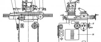
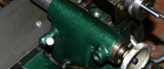
The bed is made of cast iron, solid cast, box-shaped, inside which an electric motor drives the knife shaft.
Rotation of the knife shaft is transmitted by V-belts. To tension the belts, vertical movement of the under-motor plate is provided. The belt drive is covered with a casing.
The knife shaft supports of the SF-4 are mounted in a single block with detachable covers, which reduces mechanical noise and vibration from rotation of the knife shaft. The blade shaft is braked via a belt drive by an electric motor.
Feeding of workpieces on the SF-4 is carried out manually or mechanically using an automatic feeder. The front and rear tables are cast iron, polished plates with stiffening ribs along the lower plane. The front and rear tables of the machine are adjusted vertically by means of eccentric rollers through a system of levers and rods driven by a handle for the front table and a screw with a nut for the rear table.
Shields are installed on the sides of the table. Gouging depth indicator - the dial is placed in the dashboard window. The guide ruler is moved manually. The ruler can be moved across the table depending on the width of the material being planed and can be set to the required angle in the vertical plane (up to 45°).
The machine has a round two-knife shaft with wedge fastening of knives.
Planing width on the machine is 400 mm, the thickness of the removed layer is 6 mm, the diameter of the knife shaft is 125 mm, the cutting diameter is 128 mm, the number of knives on the shaft is 2, the power of the knife shaft electric motor is 2.8 kW, the number of revolutions of the knife shaft per minute is 5000, the weight of the machine is 620 kg.
Symbol for woodworking machines
Woodworking machines and equipment are designated (indexed) with letters and numbers. Letter indexing consists of the initial letters of the name of the type or type of machine. The first letter means the type, the second and third are the main feature of the machine.
- C - circular saw (circular, circular)
- C - planing
- F - milling
- Ш - tenoning
- Tch - sharpening
- Kp - round rod
- U - universal
- PR - edge circular saw
- Central Committee - circular saw end leveler
- SF - planer and jointer
- SR - planer-thicknesser
- FS - milling with tenoning carriage
- FC - milling machine with rotary table
- SHO - single-sided tenoning
- SD - double-sided tenoning
- ShP - tenon cutter for straight tenon
- SHL - dovetail tenon cutter
- Shld - grinding disc
- ShlPS - grinding with a movable table
- TchP - saw sharpener
- TchN - knife sharpener
- TchPN - sharpening for saws and knives
The letter A indicates the presence of automation elements.
For example: SvPA—drilling and grooving machine with automatic feed. The number immediately after the letters or between them indicates the main parameters of the machines (number of cutting tools or planing width in mm, cm, dm). For example:
- Ts2K12 - two-spindle end leveler for bars 12 dm long
- SF-4 - planer and jointer with a planing width of 4 dm
- F2K - dual-spindle milling machine with rotary table
- ШО10 – single-sided tenon cutter for tenons up to 10 cm long
The number after the hyphen indicates the machine model number, for example:
- SF4-4 - fourth model
- SR6-6 - sixth model
- CP6-7 - respectively the seventh model
Longitudinal planing (longitudinal milling, jointing) on planing machines
Planing machines are designed for longitudinal planing of wood blanks in order to obtain one or two base surfaces in one pass for further processing of parts. They can be with manual or mechanized feed; one- or two-sided.
On double-sided machines, a vertical edge jointing spindle is installed perpendicular to the longitudinal axis of the knife shaft. The feed mechanism can be roller or conveyor type.
The machine bed has front and rear tables, of which the front table is longer than the back one, which ensures more accurate jointing. The tables are installed so that the back table is at the level of the protruding cutting edges of the shaft knives, and the front table is lower by the thickness of the chips being removed.
Workpieces are processed from the concave side. If a right angle is not obtained between the edge and the face of the workpiece, you need to adjust the guide ruler. Lack of stitching and tears on the treated surface occur if the tables are installed non-parallel in the longitudinal and transverse directions. Non-stitching in width is obtained when the knife shaft is deflected relative to the plane of the rear table.
The knife shaft of hand-fed jointing machines must have a guard that opens only when the workpiece passes and automatically closes after processing it.
Stages of jointing blanks on a machine
Stages of jointing workpieces on a jointing machine
- back table
- guide ruler
- workpiece
- front table
Single-spindle jointing machine SF-4
- bed
- back table
- movable fence
- guide ruler
- knife shaft
- guide rail fastening clamps
- bracket
- front table
- scale
- table height adjustment handle
Manually fed jointing machines employ one worker (machine operator), and mechanical ones employ two (machine operator and auxiliary worker). When feeding manually, the workpiece is inspected, placed on the front table of the machine and, pressing the front end of the workpiece with the left hand and the back end with the right hand, smoothly slide the workpiece onto the knives.
When the front end of the workpiece passes through the knives, the left hand is moved to press the workpiece against the back table.
The warped workpieces are placed on the table with the concave side down, pressing them tightly against the machine table.
Severely warped workpieces should not be jointed, as this will remove a large layer of wood, they will become smaller than their nominal dimensions and cannot be used for their intended purpose.
When working on machines with mechanical feed, the workpiece is fed end to end.
The thickness of the removed layer should not exceed 6 mm, and the thickness of the chips should not exceed 1.5..2 mm.
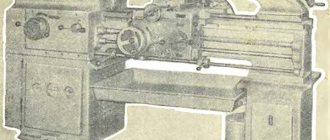
Model 2M112
2M112 is a tabletop drilling machine that was produced at the Kirov Machine-Building Plant. This capital-D drilling machine has been and continues to be used by thousands of craftsmen for cutting threads and drilling workpieces from a wide variety of metals and alloys.
The versatility of the 2M112 can be considered in the fact that it is capable of processing not only metal, but also plastic, wood and other workpieces. This makes the unit a very useful assistant in any enterprise.
Since its appearance in ancient times, technology has filled the workshops of large and small industrial enterprises. Today it can be found in numerous household and repair shops, where it regularly performs its function. In some places, the equipment is still used in large-scale production, but its moral and physical obsolescence significantly limits its use in mass production conditions.
The Soviet drilling machine 2M112 is distinguished by its simplicity and simultaneous reliability of design. The unit is very easy to master the control system. The practice of thousands of craftsmen proves its durability, and in this parameter few manufacturers can compete with this model.
The maximum drilling diameter for the 2M112 machine is 12 millimeters. The maximum distance from the table to the end of the spindle is as much as 400 millimeters, and the distance from the racks to the vertical spindle is 190 millimeters.
The machine is equipped with a powerful 550 W electric motor. The power unit provides a maximum spindle speed of 4500 rpm. At the same time, the motor is combined with a reliable gearbox, which allows you to choose one of five spindle rotation speeds.
The dimensions of the 2M112 machine are 795x370x950 millimeters with a mass of the entire structure of 120 kg. Of course, such a machine is not intended for mobile movement from one workshop to another. However, its design is rigid enough to ensure maximum precision in processing a wide variety of workpieces. Considering this feature, you can put up with a large mass
conclusions
As can be seen from the example of the 2M112 model, tabletop drilling machines of the USSR were distinguished by their massiveness, high reliability and strength of materials. Almost all units were equipped with a powerful engine, which was more than enough to work with metals and hard alloys. Interestingly, Soviet technology, although far from perfect, is very durable and repairable. Perhaps it is the last two of its qualities that explain the amazing fact that many models released decades ago continue to function to this day, performing any task set by the master.
TOP 25 drilling machines of 2022
Einhell BT-BD 701
The machine is designed for domestic use and allows precise machining of holes in both small and large workpieces. The power of this model is 630 W, which pleases buyers. Other positive aspects include 12 gears, locking at any angle and a transparent shield that prevents chips from flying away. The only drawback is the excess noise during operation.
RedVerg RD-4113
Chinese drilling machine is famous for its high quality. It makes it possible not only to make precise holes, but also to countersink and ream the same holes, regardless of the material. At the same time, the dimensions of the structure are compact, and there is nothing complicated in controlling it. When talking about disadvantages, owners often point only to a weak engine.
Knowledge 29 stunned
Do you want to sell swedes? Be aware, yak
Drilling machine "Kostroma" 2M112 USSR
Business and services » Obladnannya
10,000 UAH.
Odessa, Malinovsky Today 14:17
USSR drilling machine with three-phase motor
Business and services » Obladnannya
7,000 UAH.
Tabletop drilling machine USSR 2A112
Guaranteed to withdraw the goods, or the money back to the card. More details.
6,500 UAH.
Drilling machine. New USSR drill stand
Guaranteed to withdraw the goods, or the money back to the card. More details.
2,000 UAH.
Donetsk, Proletarsky 8 sich.
Selling USSR drilling machine
Tools » Hand tools
Guaranteed to withdraw the goods, or the money back to the card. More details.
4,000 UAH.
Drilling machine made in the USSR
Business and services » Obladnannya
6,500 UAH.
drilling machine USSR
Guaranteed to withdraw the goods, or the money back to the card. More details.
6,300 UAH.
Drilling machine USSR
Business and services » Obladnannya
1,290 UAH
drilling machine, USSR, reinforced
6,500 UAH.
Kharkiv, Chervonozavodsky 3 sich.
Drilling machine USSR
6,000 UAH.
Drilling machine USSR 2M112
Guaranteed to withdraw the goods, or the money back to the card. More details.
7,000 UAH.
Drilling machine NS-12 (USSR). 220/380 V. Urgent! Bargaining
Business and services » Obladnannya
USSR drilling machines photo
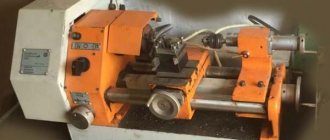
Karochi! I have long wanted a drilling machine for my garage. It’s a useful thing, and from time to time I indulge in various crafts, so a drill bit won’t hurt. First I looked at the modern Chinese ones - they look beautiful, they are inexpensive, but they are just loose, inaccurate, need to be finished and modified... And then my father-in-law customizes me some kind of Soviet machine, in very good condition! It’s a pity, but I didn’t take any photos in its original condition, but while I was trying to identify it, I found a photo of the same one:
And here is mine, already in pieces:
Before continuing with disassembly, I decided to determine what kind of animal it was. Which turned out to be not at all easy. For a couple of days I googled pictures on the topic of tabletop drilling machines of the USSR, but to no avail. They helped with identification on chipmaker.ru - it turns out that I became the happy (for now I remain optimistic) owner of the brainchild of the Kirovokan Precision Machine Tools Plant model 2D103P, for which many thanks to the experts. We have a three-phase asynchronous motor at 380V and 250W.
The designers designed this machine to drill holes up to 3mm, but, of course, I plan to install a larger chuck. I believe that Soviet hardware will withstand, because “didyvaevale! 111”, but first we need to bring it to its senses and generally start it up (I remind you that there are no starters).
Let's start to sort it out. Everything is made to perfection and fits perfectly. AND VERY HEAVY.
Important information! Dear customers and business colleagues, not all information on drilling machines manufactured in the USSR is currently available on the website. Since trade does not stand still, photographs of machines become outdated very quickly. Something is sold immediately from the sites we visit. Sometimes drilling machines require repairs - then we move them to our site and carry out the necessary repairs, restart them and equip them.
Therefore, for the current stock status and prices, call us or leave a request on the website. Running drilling machines 2M112, 2N118, 2N125, 2G125, 2N135, 2M55, 2532L or their analogues are almost always in stock.
With a huge number of negative reviews about Soviet technology, one cannot deny the fact that the USSR reached considerable heights in the machine tool industry, offering craftsmen durable and reliable equipment. Moreover, this applies to almost all areas of machine tool construction. The fact remains that Soviet machines still faithfully serve thousands of craftsmen throughout the CIS and beyond. And this only proves that the equipment designed by our engineers boasts excellent performance characteristics.
Soviet drilling machines are a separate category of metal-cutting equipment. In accordance with the classification recognized in the USSR, they belong to the group of drilling-milling-boring units. In turn, equipment from this group can be classified according to a number of other characteristics.
You can understand which group a particular device belongs to if you understand the special designations (codes) of the models. Let's consider the principle of constructing this cipher.
As you know, the name of drilling machines in the USSR was formed from several numbers and letters, each of which carries certain information. So the first digit indicates the group to which a particular unit belongs, and the second digit determines the type of machine. The third and fourth digits are necessary to indicate the dimensions of the machine.
In addition, some model names may contain capital letters. If the letter appears between the first and second numbers in the name of a particular machine, this means that the machine has been improved compared to the previous model. If the letter in the name occurs at the end of the code, then it determines the following features of the unit:
- P - speaks of the increased accuracy of the Soviet drilling machine in front of us.
- G - informs that the basic model has been subjected to a number of changes.
- Sh is a cipher that carries information that the technique can be used for a wide range of tasks.
- C is a code indicating the presence of cyclic program control in the design of the machine.
If the unit is equipped with a CNC, then at the end of the code in the name it has the letter “F” and a number following it, which can be from 1 to 4. The unit denotes a model with preset and digital display. A two indicates that the unit is equipped with a position control system. The number 3 denotes machines equipped with a contour system. Multifunctional CNC machines with an automatic tool change system are designated by a four.
USSR drilling machines were also classified depending on the size of the working surface. The minimum size option was a desktop of 200x800 millimeters, and the maximum was 500x2000 millimeters.
Tabletop drilling machines in the USSR were also categorized taking into account their intended purpose, type of device, and features of the layout of work tables and spindle units. An important classification criterion was also the accuracy and level of automation of the workpiece processing process.
To understand what drilling equipment from the times of the USSR was like, it is enough to consider one of the most popular models, which remains in demand in our time. This is what we will do in our article below.
Model 2M112
2M112 is a tabletop drilling machine that was produced at the Kirov Machine-Building Plant. This capital-D drilling machine has been and continues to be used by thousands of craftsmen for cutting threads and drilling workpieces from a wide variety of metals and alloys.
The versatility of the 2M112 can be considered in the fact that it is capable of processing not only metal, but also plastic, wood and other workpieces. This makes the unit a very useful assistant in any enterprise.
Since its appearance in ancient times, technology has filled the workshops of large and small industrial enterprises. Today it can be found in numerous household and repair shops, where it regularly performs its function. In some places, the equipment is still used in large-scale production, but its moral and physical obsolescence significantly limits its use in mass production conditions.
Criterias of choice
Power.
This parameter should be selected depending on where the machine is used. So, when used for commercial purposes, the best option would be a power of 600 W or more. If the device will be used in a house or garage, then it is better to consider models with less power.
Hole.
Its diameter for domestic purposes should be no more than 16 mm, but in the production chain, where deep holes are needed, a figure of up to 60 mm will be required.
Performance.
The higher it is, the faster and better the machine will do its job. And the magnitude of productivity is ensured by light-weight structures with provided rotation modes and illumination of the working area.
Safety.
You shouldn’t forget about it either, because a drilling machine, if used incorrectly, can cause serious damage to human health. To prevent adverse consequences, a transparent protective screen must be provided on the structure to prevent the emission of sawdust and shavings.
Additional features.
These include: thread reverse, coolant supply system, lighting, etc. Many modern machines can boast of such additions.
Similar material
Information about the manufacturer of the tabletop drilling machine NS-12
The developer of the tabletop drilling machine model NS-12 is the Special Design Bureau of Special Machine Tools SKB-3, Odessa . SKB-3 was created in 1947 and existed until the mid-90s.
The machine was produced by machine tool factories and several vocational and technical schools of the Soviet Union in the 50s..70s of the last century.
The NS-12 desktop drilling machine has several modifications (NS-12, NS-12A, NS-12B, NS-12M), which differ slightly from each other in design and configuration.
NS-12 tabletop drilling machine. Purpose and scope
The machine is designed for drilling holes and cutting threads in small parts made of cast iron, steel, non-ferrous alloys and non-metallic materials in industrial enterprises, repair shops and household workshops.
Main parameters of the drilling machine NS-12B:
- Maximum drilling diameter: Ø 12 mm
- Maximum drilling depth: 100 mm
- Maximum height of workpiece: 400 mm
- Distance from spindle axis to column (spindle overhang): 200 mm
- Spindle speed: 450, 710, 1400, 2500, 4500 rpm
- Electric motor power: 0.6 kW
- Machine weight: 130 kg
The spindle assembly of the NS-12 drilling machine is the most complex and precise assembly in the machine. The spindle assembly is mounted in the spindle head. Main parts of the spindle assembly:
- Spindle - a shaft that rotates on 2 angular contact bearings inside the spindle sleeve;
- The spindle sleeve (quill) is a cylinder that is mounted in the spindle head and has the ability to move axially within 100 mm.
The upper part of the spindle has splines to receive rotation from the take-up pulley, the lower part has a Morse taper for attaching the drill chuck.
The spindle of the NS-12 machine receives five rotation speeds from five-stage drive pulleys, which provides free choice of cutting speeds of 450, 800, 1410, 2490, 4430 rpm.
The quill, inside which the spindle rotates, has a stroke of 100 mm and is balanced by a spiral spring, which returns the quill to the upper (original) position. The quill is raised and lowered by a rack and pinion. The maximum cutting force allowed by the mechanism is 70 kg.
The end of the spindle of the NS-12 drilling machine is an internal Morse cone No. 1, D = 12.065 mm according to GOST 25557 (Tool cones). To install a standard drill chuck with a shortened cone on the machine, you need to install a mandrel in accordance with GOST 2682 (Mandrels with a Morse taper for drill chucks).
On the NS-12 machine you can install one of 4 mandrels in accordance with GOST 2682:
- Mandrel 6039·0002 - version 2, shortened Morse taper B10
- Mandrel 6039·0005 - version 2, shortened Morse taper B12
- Mandrel 6039·0007 - version 2, shortened Morse taper B16
- Mandrel 6039·0011 - version 2, shortened Morse taper B18
So, using one of the 4 mandrels, you can install a drill chuck of one of 6 standard sizes in accordance with GOST 8522 (Three-jaw drill chucks).
- Chuck 4 - shortened Morse taper B10 , clamping range - 0.5..4 mm
- Chuck 6 - shortened Morse taper B12 , clamping range - 0.5..6 mm
- Chuck 8 - shortened Morse taper B12 , clamping range - 1.0..8 mm
- Chuck 10 - shortened Morse taper B16 , clamping range - 1.0..10 mm
- Chuck 13 - shortened Morse taper B16 , clamping range - 1.0..13 mm
- Chuck 16 - shortened Morse taper B18 , clamping range - 3.0..16 mm
An example of a symbol for a 3-jaw drill chuck, size 16, with a connecting conical hole B18:
Cartridge 16-B18 GOST 8522-79
Morse cone instrumental shortened
Tool taper - Morse taper is one of the most widely used tool mounts. It was proposed by Stephen A. Morse around 1864.
The Morse taper is divided into eight sizes - from KM0 to KM7 (in English: MT0-MT7, in German: MK0-MK7).
Morse taper standards: GOST 25557 (Tool cones. Main dimensions), ISO 296, DIN 228. Cones made according to inch and metric standards are interchangeable in everything except the shank thread.
For many applications, the length of the Morse cone turned out to be excessive. Therefore, a standard was introduced for nine standard sizes of shortened Morse cones (B7, B10, B12, B16, B18, B22, B24, B32, B45), these dimensions were obtained by removing the thicker part of the cone. The number in the designation of a short cone is the diameter of the thick part of the cone in mm.
- B7 - Morse cone KM0 , D = 7.067 mm;
- B10 - Morse cone KM1 , D = 10.094 mm. Cartridge 4-B10 (0.5÷4 mm);
- B12 - Morse cone KM1 , D = 12.065 mm. Cartridge 6-B12 (0.5÷6 mm), Cartridge 8-B12 (1÷8 mm);
- B16 - Morse cone KM2 , D = 15.733 mm. Cartridge 10-B16 (1÷10 mm), Cartridge 13-B16 (1÷13 mm);
- B18 - Morse cone KM2 , D = 17.780 mm. Cartridge 16-B18 (3÷16 mm);
- B22 - Morse cone KM3 , D = 21.793 mm. Cartridge 20-B22 (5÷20 mm);
- B24 - Morse cone KM3 , D = 23.825 mm;
- B32 - Morse cone KM4 , D = 31.267 mm;
- B45 - Morse cone KM5 , D = 44.399 mm.
Technical characteristics of the jointing machine SF4-1
| Parameter name | SF4-1 | SF6-1 |
| Basic machine parameters | ||
| Maximum width of processed material, mm | 400 | 630 |
| Maximum depth of layer to be removed, mm: | 6 | 6 |
| Size, mm | 1504 x 412 | 1504 x 650 |
| Rear table size, mm | 1004 x 412 | 1004 x 650 |
| Cutting speed, m/s | 34 | 34 |
| Minimum length of processed material, mm | 400 | 400 |
| Front table lifting height, mm | 6 | 6 |
| Lifting height of the rear table, mm | 2 | 2 |
| Price for dividing the rear-front table lifting dial, mm | 1 | 1 |
| Number of knife shafts | 1 | 1 |
| Knife shaft body diameter, mm | 125 | 125 |
| Diameter of cutting circle of knife shaft, mm | 128 | 128 |
| Number of knives on the knife shaft, mm | 2/ 4 | 2/ 4 |
| Knife shaft speed, rpm | 5100 | 5100 |
| Braking method | electromech | electromech |
| Braking time of the knife shaft, s, no more | 6 | 6 |
| Number of chip receivers | 1 | 1 |
| Diameter of chip receiver, mm | 175 | 175 |
| Electrical equipment of the machine | ||
| Type of supply current | 380V 50Hz | 380V 50Hz |
| Number of electric motors on the machine, pcs. | 1 | 1 |
| Electric motor - rated power, kW | 3 | 5,5 |
| Dimensions and weight of the machine | ||
| Machine dimensions (length x width x height), mm | 2564 x 1385 x 1250 | 2564 x 1715 x 1250 |
| Machine weight, kg | 705 | 950 |
- Single-sided jointing machines SF4-1, SF6-1. Operating manual SF.00.01 ARE, 1977, Kurgan
- Amalitsky V.V. Woodworking machines and tools, 2002
- Afanasyev A.F. Wood carving, Technique, Tools, Products, 2014
- Bobikov P.D. DIY furniture, 2004
- Borisov I.B. Wood processing, 1999
- Jackson A., Day D. Woodworking Bible, 2015
- Golden Book of woodworking for the owner of a country plot, 2015
- Ilyaev M.D. Wood carving, Master's lessons, 2015
- Komarov G.A. Four-sided longitudinal milling machines for wood processing, 1983
- Kondratyev Yu.N., Pitukhin A.V... Technology of wood products, Product design and calculation of materials, 2014
- Korotkov V. I. Woodworking machines, 2007
- Lyavdanskaya O.A., Lyubchich V.A., Bastaeva G.T. Basics of woodworking, 2011
- Lyubchenko V.I. Thicknessing machines for wood processing, 1983
- Manzhos F.M. Wood cutting machines, 1974
- Rasev A.I., Kosarin A.A. Hydrothermal processing and preserving of wood, textbook, 2010
- Ryzhenko V.I. The Complete Encyclopedia of Wood Art, 2010
- Rykunin S.N., Kandalina L.N. Woodworking technology, 2005
- Simonov M.N., Torgovnikov G.I. Debarkers, 1990
- Soloviev A.A., Korotkov V.I. Setting up woodworking equipment, 1987
- Sukhanov V.G. Circular saws for sawing wood, 1984
- Fokin S.V., Shportko O.N. Woodworking, Technologies and equipment, 2017
- Hilton Bill Woodworking, The Complete Guide to Stylish Home Furniture Making, 2017
Bibliography:
Related Links. Additional Information
- Directory of woodworking machines
- Manufacturers of woodworking machines and equipment
- Manufacturers of household woodworking machines
- Manufacturers of chipping machines
- Classification of woodworking machines
- Machines for longitudinal cutting of lumber
- Sawmill frames. Classification
- Lumber. Basic concepts. Terms and Definitions
Home About the company News Articles Price list Contacts Reference information Interesting video KPO woodworking machines Manufacturers
Location of components of the drilling machine NS-12
Location of components of the drilling machine NS-12
Specification of components of the drilling machine NS-12
- Plate
- Column
- Trunk (spindle head)
- Spindle sleeve (quill)
- Spindle
- Spindle quill feed handle
- Rack
- Electric motor
- Electric motor plate (sub-motor plate)
- Belt tensioner stopper
- Shoe (bracket for fastening the column to the plate)
Brief description of the design and operation of the NS-12 desktop drilling machine
The machine consists of the following main parts: plate 1; column 2; trunk with spindle group 3; electrical equipment 8.
to the plate , in the hole of which a column 2 is installed. The column is secured by tightening the shoe.
Along the perimeter of the plate there is a trench for collecting coolant. At the bottom of the chute there is a drain hole with a plug. When connecting the machine to a centralized supply of emulsion, instead of a plug, a nipple with a rubber hose can be wrapped.
A step-down transformer and a package switch housing (for local lighting) are mounted inside the plate, and a push-button station is installed outside (for the machine’s electric motor).
to the column (Fig. 4) (m = 2), in mesh with which there is a gear mounted in the trunk, rigidly fixed to the handle 4 (see diagram of the location of the controls). When turning handles 3, 4 (Fig. 6), the trunk moves along the column. After installing the trunk to the required height, handle 3 clamps the trunk.
A spindle group 5, an electric motor 8 with a plate and a tensioner 10 for the V-belt are attached to the trunk
The spindle , unloaded from the pulley, is installed in sleeve 4 (quills) on precision angular contact bearings.
The sleeve moves when handle 6 is turned (Fig. 1).
The transmission of rotation from the pulley to the spindle is carried out using two parallel keys.
The five-speed spindle pulley is secured by a bushing on two radial bearings.
The electric motor is mounted on a sub-motor plate, the guides of which freely fit into the corresponding bores in the trunk. After the belt is thrown onto the corresponding pulley stage, this plate is pulled away from the trunk to the normal belt tension and in this position is fixed with clamping screws.
Specifications
Machine design
The machine has good performance. In addition to its reliable design, it is characterized by acceptable processing parameters for wooden workpieces. You can familiarize yourself with them by studying the technical data sheet of the equipment.
The dimensions of the machine are 256.4*138.5*125 cm. At the same time, its assembled weight does not exceed 705 kg. When planning the installation, you need to take into account that in addition to the free space for supplying workpieces, they often provide for connecting the unit to a chip vacuum cleaner. This will require additional work space.
To create an optimal production scheme, you need to familiarize yourself with the main characteristics of the woodworking machine of this series:
- maximum width of the processed workpiece – up to 40 cm;
- jointing depth can reach 6 mm;
- Dimensions of work tables. Front – 150.4*41.2 cm, rear – 100.4*41.2 cm;
- cutting speed is 34 m/s;
- minimum length of the workpiece - 40 cm;
- permissible lifting height of tables. Anterior – 6 mm, rear – 2 mm;
- knife shaft diameter – 12.5 cm;
- the number of knives can be 2 or 4 pcs.;
- the speed of the electric motor is not adjustable and is equal to 5100 rpm;
- the final stop time of the working shaft is 6 seconds.
To increase productivity, the design of the machine includes an electromechanical device for forced stopping of the knife shaft. To avoid clogging of the mechanisms, a container for chips is installed in the lower part of the housing. Its diameter is 17.5 cm.
To connect the machine engine to the power grid, a three-phase 380 V line is required. It should be taken into account that the rated power consumption of the power unit is 3 kW.
Location of controls for the NS-12 drilling machine
Location of controls for the NS-12 drilling machine
Specification of controls of the NS-12 machine
- Stop button
- Electric motor start button
- Handle for clamping the trunk (spindle head) on the column
- Handle for raising and lowering the trunk (spindle head) along the column
- Quill lifting handle for manual spindle feed
- Tensioner Clamp Screws
- Local lighting switch
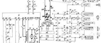
Electrical equipment of the single-sided jointing machine SF-4
General information
The machine is equipped with a three-phase squirrel-cage asynchronous electric motor
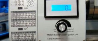
The machines are manufactured with electrical equipment designed to operate at a voltage of 380 V 50 Hz, in power circuits, in control circuits at a voltage of 110 V 50 Hz, and in the lighting circuit 24 V 50 Hz. Machines can be manufactured with operating voltage according to the work order.
Electrical circuits use PGV brand wire with a cross section of 1 mm2 red and 1.5 mm2 black, 2.5 mm2 2-color green-yellow or green.
There are interlocks in the electrical circuits that make it impossible to turn on the main drive electric motor when the belt drive covers are removed and when the blade shaft fan is removed.
During operation of electric motors, systematically carry out their technical inspection and preventive repairs.
During preventive maintenance, the electric motor must be disassembled, internal and external cleaning and replacement of bearing grease.
Before filling with fresh grease, the bearings must be thoroughly washed with gasoline.
Kinematic diagram of the drilling machine NS-12
Kinematic diagram of the drilling machine NS-12
- Rack on spindle sleeve
- Gear for moving the spindle sleeve
- Gear rack on column
- Gear for moving the trunk (spindle head) along the column
Description of the kinematic scheme
From the electric motor, using a V-belt drive through a five-speed pulley, the machine spindle connected to it by means of keys (and sliding along them) is driven into rotation.
When handle 5 (Fig. 6) is turned, gear 2 (Fig. 4) rotates, which moves rack 1 and the sleeve associated with it up and down.
The sleeve, moving in the cavity of the trunk, moves up and down the spindle, connected to the sleeve by angular contact ball bearings.
The vertical movement of the trunk is carried out by the action of gear 4 (Fig. 4), driven into rotation by handle 4 (Fig. 6), on rack 3 (Fig. 4), mounted on the column.
If necessary, it is possible to rotate the column together with the trunk around its axis after loosening the clamp of the shoe in which the column is secured.
The belt guard casing is either cast or welded (extended).
Electrical equipment and electrical circuit of the drilling machine NS-12
Electrical diagram of the drilling machine NS-12
Electrical equipment of the drilling machine NS-12
The electrical equipment of the machine consists of:
- electric motor 0.6 kW
- push-button starter with “Stop” and “Start” buttons
- local lighting with step-down transformer and package switch
Control of the NS-12 machine
1. By pressing the “Start” button of the push-button starter, the electric motor is turned on. By pressing the “Stop” button of the gearbox push-button starter, the electric motor is turned off.
2. By turning the handle of the packet switch VO, the local lighting of the LO is turned on. The machine must be grounded.
Drive of the machine NS-12
The electric motor is attached to the spindle head by means of a submotor plate. On the axis of the electric motor there is a stepped pulley, which is connected to the spindle pulley by a V-belt.
Local lighting of the NS-12 machine
The machine is equipped with equipment for local lighting. Due to the fact that the tabletop drilling machine, model NS-12, is most often installed on workbenches or tables, therefore, the fittings (bracket) and the apparatus (transformer) for local lighting, when installing the machine, must be attached near the machine, and if the machine is installed near walls - then to the last one.