Spread the love
Fixtures and equipment are the most important component of successful work on CNC machines.
Fixing is a general term for any device that is used to securely hold a workpiece during processing.
“Fixtures” are solutions for fastening parts that are custom made for a specific part or situation.
Job retention has two components:
- The actual clamping device, such as a milling vice.
- A method for placing and securing this jig on your machine. This includes the ubiquitous T-slots, modular mounting plates, 4th axis solutions and more.
We'll look at different methods for locating restraints and then describe the choices for restraints.
But first, let's talk about why tooling and fixtures are so important, and how to know when you need to make special fasteners.
Equipment and devices: types and types
In the West, there is a saying among milling operators: “fixtures are where you make your money,” which translates roughly as: “Fixtures are what you make money from.” If you can make gadgets that save time, you will reap big profits.
T-slots
T-slots are the most common method of positioning and holding your work fixture. They are simple, reliable and work. To attach anything to a T-slot table, use T-slot nuts and matching studs or other fasteners that fit the nuts.
T-slot nuts
Although they are common, they have some disadvantages compared to other solutions. Aside from the fact that T-slots can collect chips and other debris, their biggest disadvantage is that it makes it difficult to return your vise or other table mount fixture to the exact same location and orientation. This can result in additional work each time the machine must be set up with new work attachments for a new job. Over time, the cost of such inefficiency can be quite high.
Just imagine what if, instead of a tool changer and tool table, you had to dial in each tool every time you used it? Wouldn't this be a huge barrier to improving the productivity of your processing workflow? Well, setup time can also be a big hindrance to productivity, and T-slots don't help here.
There are a few solutions that tried to make them a little better:
Devices for milling work
Devices for milling must be more massive and durable than for drilling, due to the presence of variable cutting forces, especially when milling with cylindrical cutters, which, in addition, create a force that tears off the product;
This circumstance must be taken into account when designing clamps.
The design of the clamps must be durable and convenient for quick fastening and release of the product. Performing work on two or more devices allows you to change products during the machine processing time on another device.
Fig. 736. Rotary table for milling.
For this purpose, in many cases it is necessary to use rotary tables. Continuous milling methods necessitate the design of compact devices that quickly fasten products.
To install tools during milling, as well as for planing, dimensions that determine the dimensions are widely used.
products that should be obtained after processing.
Dimensions must be placed in each device for milling and planing; they do not complicate the fixtures and at the same time significantly speed up the installation of the tool.
Rotary tables are widely used in medium and large-scale production for milling mainly on two devices: while the product is changed in one device, milling is carried out on the other, as a result of which auxiliary time is reduced to almost zero.
The rotary table (Fig. 736) has a fixed base A, which is mounted on the machine table, and an upper rotating part B, the rotation of which is fixed by a pin C using a spring D. Conclusion
the fixing pin is made by handle E. The rotating part is fastened to the bottom by two strips K using a roller L, which has two eccentric necks that fit into the grooves of the rods M. When turning the handle II of the roller neck L, the rods M are pulled downwards, as a result of which the upper plate is pressed against the lower one basis.
Fig. 737. Rotary table for mounting two devices.
In fig. 737 shows a rotary table (general view), differing from the previous one only in the location of the grooves for fastening devices.
Fig. 738. Rotary table for one device with 180° rotation.
In fig. 738 shows a rotary table for one fixture, when the product is processed on both sides with a rotation of 180°.
A special feature of this table is roller A, which has an eccentric in the center of the table, when turning it, the table is raised by means of bushing B and a ball bearing, which facilitates rotation of the table;
when milling, the same roller A, on the contrary, presses the upper rotating part G to the lower one with the bushing B. Roller E with teeth cut at the end is engaged with rack and pinion retainer K; it is moved away from the top of the table using handle L and is turned on itself under the action of spring M.
Fig 739. Device for milling a lever on both sides.
This table is used for fixtures like the one shown in FIG. 739, on which two levers are milled simultaneously;
First, the bosses of the levers are milled at one end, then the device is rotated 180° and the bosses are milled from the other end.
The levers are installed with one side on the prism and the other on the plane.
Fig. 740. General view of a device for milling levers on a rotary table.
In the transverse direction, the levers are pressed against a constant support by an asterisk shown in Fig. 740 (general view).
On the same rotary table, installed on a special two-spindle horizontal milling machine, the lower head of the connecting rod is cut and places for the bolt head and nut are milled.
Fig. 741. Device for cutting the head and milling for connecting rod bolts on a rotary table.
The device is attached to the upper rotating part of the table and with it rotates through an angle of 180° (Fig. 741).
The connecting rods are mounted on two guide pins; the cut head is secured with a removable washer and nut.
On milling and slotting machines, special rotary tables are sometimes an accessory of the machine and differ from those described above in that they can be used for continuous milling around a circle with mechanical rotation from the machine (Fig. 742).
Fig. 742. Special rotary table.
On the top of such a table A (Fig. 742) there are T-shaped grooves for attaching devices. The rotation of the table is carried out by a worm gear. Worm B is rotated by handwheel C by hand or mechanically from the machine through a hinge gear and bevel gear D. Two bevel gears E, sitting on the shaft of worm B, make it possible, using a cam clutch E, to impart right and left rotation to the table. When the table rotates
manually, the clutch is moved to the neutral position by the fork L. The fork can be switched automatically by moving the rack roller M from the gear roller H, at the upper end of which a lever P is attached, rotating from a cam P screwed on the rotating part of the table. To use the table as a dividing head, divisions are applied to the cylindrical stationary part of the table, indicating degrees of rotation angle.
To quickly rotate the table, the worm can be turned off by turning the eccentric sleeve T using a clamp F.
Fig. 743 Connecting rod continuous milling fixture mounted on a rotating table.
In fig. 743 shows a device for continuous milling of the parting plane of a connecting rod mounted on a mechanically rotating table, similar to that described above. The connecting rod is fixed in three centers.
Fig. 744. Suitable for continuous milling of pusher flats on a rotating table.
A device is installed on the same table for continuous milling of pusher flats, secured in four pieces in two rows with one bolt (Fig. 744).
Fig. 745. Rotary table on a slotting machine.
The same tables are used on slotting machines for chiseling parts around a circle, as shown in Fig. 745.
Fig. 746. Small turntable.
In fig. 746 shows a small rotary table mounted on the table of a milling or some other machine. Rotation can be done in two directions.
Fig. 747. Turntable.
In fig. 747 shows a rotary table, used mainly on radial drilling machines; it can also be used when working on milling and slotting machines.
Fig. 748. Rotary squares.
Fig. 749. Special dividing head.
Small turning angles are shown in Fig. 748.
For devices in which products are installed in a vertical plane so that they can rotate, use
universal and special dividing heads.
Universal dividing heads are part of one or another machine. Special dividing heads come in various designs depending on the purpose.
Fig. 750. Pneumatic device for simultaneous milling of both sides of connecting rod heads.
One such 90° division head is shown in FIG. 749. This head has a detachable wedge that gives precise division.
Recently, such heads are being replaced by more convenient heads with spring clamps.
Pneumatic devices are widely used, especially in large-scale and mass production.
One of these devices for simultaneous milling of both sides of the upper and lower heads of an automobile connecting rod
engine on a special four-spindle machine is shown in Fig. 750. A pneumatic cylinder, through a system of levers, presses the upper head of the connecting rod with clamp A to the stationary clamp B, and the lower head with clamp D to the swinging lever E. Stopper C serves for approximate installation in the transverse direction.
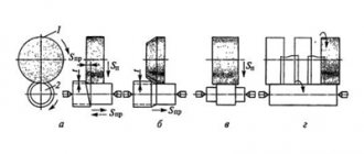
A simple jig for milling wedges at an angle is shown in FIG. 751.
First, clip A is milled, which is then transferred to place B for milling the second side. To pre-install the cutter, use a plate - a “dimension” from which using a 3 or 5 mm thick probe. distance is measured. The product is clamped with straps. The device is attached to the table with bolts C.
Vices and fixtures with key
If your T-slots are correct, you can install wrenches on the bottom of the vise or mounting plates that line up with the T-slots. You can also install the wrenches in T-slots that line up with the edge of the vise plate or base. This can save you quite a bit of time pulling out vices and such, and it's not difficult, so it's definitely worth thinking about.
The problem is that these solutions will help with one dimension (usually the short table dimension is the Y axis and is perpendicular to the slots), but we still have the problem of positioning along the T-slot axis. .
Luckily, there is a better way - auxiliary mounting plates (also called mounting plates).
Mounting plates, tooling plates and modular fastening
Accessory fixture plates (also called fixture plates or tool plates) are plates that fit on top of a T-slot table to provide a new way to position and secure fixtures. A typical tool plate looks like this:
Typical mounting plate
Tooling plates typically use a pattern of holes that alternate between holes for precision locating pins and threaded holes for fasteners. If this mesh is positioned accurately (or even if it is not and the positions are precisely known), you have a very repeatable way to install the tooling on the plate. The locating pins ensure precise positioning to within 0.01. Imagine being able to install a vise on a separate mounting plate with mounting pins and mounting holes, the repeatability of this operation will be about 0.01. If all your fixtures can fit on the tooling plate, you can actually switch the machine to a new fixture configuration very quickly. Saving time allows you to quickly recoup the cost of such a system.
The vise can be installed on one of these plates within one or two minutes. A CNC machine can be reconfigured in 5 or 10 minutes for a completely different job. In addition, the skill required of machine operators, as well as the likelihood of errors, are greatly reduced if fixtures do not have to be carefully adjusted each time. There are also advantages to creating modular G-code because it can rely on a positioning grid.
If accuracy greater than 0.01 is required, it is often better to use probing along with the selected g-code parameterization to correct the remaining error. You can try to fine-tune the parameters manually, but the probing solution may rely on everything being nearly correct to determine the last little bit of error correction that needs to be applied in the g-code itself. For example, you can very accurately apply rotation to g-code based on sensor output (aligning objects to axis motion).
Tool plates are usually made of cast iron or aluminum, although steel plates are also available. They can be purchased or made from scratch. For a complete guide, be sure to visit our page on mounting plates.
Types of milling equipment and tools
These products are presented in a variety of designs, differing in type, design, purpose and other parameters. There are the following categories:
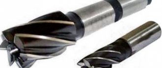
- Cutting tool. These are a variety of cutters, plates, drills, heads, devices for thread processing, microtools, boring systems.
- Spare parts: cartridges, support plates, pins, mounting screws, clamps and other components.
- Tooling. This includes modular and solid angular heads, multipliers, starter (standard) kits, tool holders, extensions and adapter sleeves, and stop blocks.
- Accessories. This is a large category, including different types of collets and collet adapter chucks, clamping keys and nuts, adapter sleeves, pins, racks for tool assembly, plugs, extensions for shrink chucks, etc.
- Clamping fixtures. To fix workpieces, you need to buy a machine vice; quick-change fastening systems, compact clamps, and various types of vacuum equipment are also offered.
- Consumables. They do not affect the functionality of the machine, but are vital for its operation. These are oils and other lubricants, filters and filter elements, air guns with hoses, sweeping brushes, washing guns and hoses for them, etc.
- Probes and other accessories. This category includes frangible fuses, adjustment and measuring probes, alignments, extension cords and other devices, including for contact sensors.
Ball locks and other solutions for quick tool insert changes
By now I hope you can see how much setup time you can save by using tooling plates. What could be better? There are at least two different ways to make setting up fixtures and accessories even easier: quick-change tool plates and trays.
With the Quick Change system, the time required to handle locating pins and fasteners is reduced with some kind of integrated solution that allows for precise positioning and very fast locking. One of them is the ball lock system:
Ball lock system
Ball locks are a system for quickly removing and installing tool plates. This system provides precise positioning and secure retention with 4 ball locks. Simply align the plate with the accessory plate (which has receiver bushings and is mounted on the table), drop the retainer ball shanks into the hole, tighten the bolt on top of the retainer ball shank, and you're done. It's really quick and easy to install four bolts without fiddling with locating pins or additional fasteners. We are talking about a 30-second changeover time, which is really very fast.
DEVICE
A significant part of the equipment of a milling machine consists of devices for installing the cutting tool and transmitting torque to it.
These include clamping devices (chucks), mounting mandrels and adapter sleeves.
Collet chucks are widely used as devices for working with tools equipped with cylindrical shanks, providing reliable fixation and transmission of significant torque, as well as centering accuracy. The chucks are available with tapered shanks of all sizes and are equipped with a set of collet bushings covering a wide range of tool diameters.
A special group of equipment that expands the functionality of the equipment consists of slotting and boring heads. The use of a slotting head will allow processing of blind keyed, splined and other surfaces that are inaccessible to cutting with a rotating tool, and with the help of boring heads it is possible to process internal grooves and end grooves.
The configuration of the milled surface is determined by the relative position and trajectory of the relative movement of the workpiece and the cutting edges of the tool. Installation and clamping devices are designed to ensure the specified position of the part in the working area of the machine.
Wedge stepped clamps are used for fixation on the work table. They allow you to securely fasten a part of a fairly complex shape.
There is a wide range of machine vices available. With their help, you can install the workpiece in any position, and with high precision. Many models provide rotation in several planes and quick changeover.
To solve such problems, various types of rotary tables are also designed, including those with longitudinal-transverse movement, and jaw chucks and tailstocks can be used to secure the rotating surfaces.
The processing of surface elements evenly distributed around the circumference is carried out using dividing heads and dividing disks, which are equipped with rotary tables.
Pallets
The next step is pallets. It's like automatic tool plates when everything else was manual. A typical pallet machine allows you to adjust one while the machine is working on another. Changing the pallet occurs by removing the old pallet outside the milling zone of the machine and installing a new one. This minimizes the amount of time the machine must be idle and allows adjustments to be made in parallel with processing.
Some machines have what are called "pallet pools", which allow you to set up multiple pallets in advance and schedule them to run. A pallet pool can allow a machine to run unattended for quite some time and can be a useful part for full automation.
Pallets are typically only seen on horizontal machining centers and some high-performance vertical machining centers. This is a full production feature that is quite expensive, so the cost needs to be justified.
4th axis, journals and tool columns
Sometimes it is useful to be able to apply another dimension to our thinking - in this case, the 4th Axis. In CNC, the 4th axis is usually the rotary axis. It is aligned to rotate along an axis parallel to one of the other three axes of the machine. On vertical machines, the 4th axis is often parallel to X or Y and routed downwards. On horizontal ones, the 4th axis is also parallel to X or Y, but it is vertical.
From a workplace perspective, the 4th axis can be used to introduce new orientations for two purposes:
1. It allows access to more sides of the part so processing can continue without the need to turn parts over by hand.
2. This allows access to more parts that can be positioned around the 4th axis.
To learn more about these applications, check out our excellent 4th Axis Basics series.
Devices and equipment. Working solutions
Having figured out how we are going to place and attach our attachment to the milling machine, let's look at what types of attachment there are in principle.
Milling vice
Pair of milling vicesOLYMPUS DIGITAL CAMERA
Today, the most popular solution for fixing workpieces is a vice. There are many manufacturers of these vises, a notable example being Kurt, who produced the first vises in the 1950s.
For a more detailed description of the machinist's vice, see our Complete Guide to the Vise. It's full of useful information.
Clamps, accessories and fixtures for plates
As useful as vices are, they do have their drawbacks. They have a hard time working with really large plates, although as mentioned, you can move the jaws to the extreme position for medium-sized plates. And they may also not be optimal for very small parts. Of course, you can place multiple parts in an array, but this is often inconvenient.
It's difficult to get small parts to fit so tightly with a vise, but the plate jig makes it easy. Mitee Bite Pit Bull clamps are used here. The effect is not unlike a tiny milling vice that fits every part perfectly.
When it comes time to handle large sheets or a lot of small parts, it's usually time to take the vise off the table and use clamps.
Step clamps
The most common type of clamp is called step clamp because it has small steps machined into it. They are typically used with T-slots, although you can also bolt them into the tool plate. Here are some typical stepped clamps:
The step clamp pressure plate, the step block supporting end of the clamp, and the bolt pass through the T-slot nut
Step Clamp Set
The photo shows a typical set of stepped clamps. It may be handy to stock up on an extra set so you have more clamping parts to work with. By stacking stepped blocks on top of each other and using longer bolts, you can clamp fairly tall workpieces. When using stepped clamps, keep the bolt close to the workpiece rather than the stepped block. It may be helpful to tilt the clamp onto the piece, raising it a step or two from level. You can also place a pad of soft material between the clamp and the workpiece to prevent damage to the workpiece.
Clamping blocks
Step clamps grip the top of the workpiece, which is sometimes inconvenient because you may need to machine the captured area. Toe clamps grip the side of the workpiece, allowing full access to the top of the workpiece. Many different types available:
This toe clamp moves the clamp down the ramp as it is tightened to press against the workpiece
These Mitee Bite Edge clamps have an eccentric bolt head that forces the hex against the workpiece as you tighten it.
Double-sided tape, glue, wax and low melting point alloys
Some workpieces are very difficult to hold because they are thin or because of their shape. As a rule, it is simply impossible to clamp them. Solutions for these situations include double-sided tape, glue, wax, and low melting point alloys.
The glue should be something that is released when needed. For example, Super Glue releases at a certain temperature, as does LocTite. The fumes from it are toxic, so try to remove them with good ventilation. Double-sided tape works great, especially for very thin materials.
Wax and low melting point alloys (usually bismuth alloys). They can be used to build up the workpiece and create a gripping zone. When processing is complete, the wax or alloy can be melted and stored for reuse.
Vacuum devices
Do you need to apply even pressure to hold the part? It can generate significant holding force given sufficient surface area. And it doesn't depend on the shape or how thin the material is. We have a good article on how to make your own vacuum attachments.
Perhaps the biggest disadvantage of vacuum tools is that their clamping force is limited by the surface area. Because of this, small parts can come off relatively easily. When the cutting forces exceed the clamping force that the vacuum table can provide, the part will pop out and deteriorate. This is a common problem for vacuum table users. This is especially true for small parts that do not have a large surface area.
Chucks and collets: for round parts
Typically round parts are machined on lathes, although in many cases milling may be required. If you have a lathe/mill, it may not be necessary to put it on a milling machine. But if you just need to work on some round parts on the router, you can use the same fasteners as for lathes. Simply bolt them on or press them against the mill table. For example, use a three-jaw chuck or a collet chuck set.
Lathe chucks are especially common on 4-axis because we often start with a round workpiece.
From time to time we put round pieces on the table because it's much faster. Consider this setup for processing round parts:
4-axis installation
I would never have thought, but many experts say that this 4-axis setup is very effective. It was capable of cutting aluminum rods to length, providing square edges, and drilling and tapping holes faster than a lathe.
Expansion mandrels, mandrels and studs
We can use expansion mandrels, mandrels or studs. The idea is to place the flared cylinder into a hole on the underside of the workpiece. This will secure the workpiece in place. So, you can access the workpiece from all sides except the bottom. This way, you won't collide with the support being processed (you need to remember where the mandrels are so you don't have one in the middle of the pocket!).
Here's a fixture using flared studs:
Turning the bolt spreads the pin apart to allow the workpiece to be clamped
There are many similar devices available to suit your needs. These are especially common for lathes, but as we already mentioned, you can use a lathe tool at work if you can find a way to secure it to the table.
Devices for installing workpieces on milling machines
When performing universal work related to milling planes, workpieces are installed on a milling machine in three main ways: in a vice, on the machine table, on corner plates.
Relatively small workpieces are secured in a vice. Large workpieces (such as plates, housings) are placed on the machine table. To strengthen large workpieces, the processed surfaces of which must be located at a certain angle to each other, corner plates are used.
Milling fixtures
To install and secure workpieces on the machine when milling planes, general-purpose milling devices are used: machine vices, clamps, clamps, stops, corner plates.
machine vices are divided into fixed, rotary and universal; according to the method of operation - with manual and mechanized drive; in terms of accuracy - normal class N and increased - class P.
A fixed vice consists of a body with a fixed jaw and a movable one.
The latter is installed on rectangular housing guides and connected to them by straps. It is driven manually by rotating a handle placed on the square of the screw. Attached to the vise jaws are steel hardened overhead jaws with a corrugated or smooth working surface, designed for securing workpieces. Guide keys are used to align the vice on the machine.
Rotary vices differ from non-rotating ones by the presence of a base with a degree scale.
Thanks to this, the body of such a vice can be rotated to the required angle and secured with bolts and nuts. The universal vice is characterized by the ability to rotate the body in two planes - horizontal and vertical. Therefore, they are used when milling inclined planes and bevels located in different directions. A mechanized vice with a pneumatic or hydraulic drive significantly reduces the physical load of the milling operator and increases labor productivity.
In a vice with a piston pneumatic drive, compressed air from the workshop network enters through a fitting into either the right or left cavities of the pneumatic cylinder (depending on the position of the distribution valve handle). In this case, the piston together with the rod, screw, nut and movable jaw will move progressively left or right, clamping or pressing the workpiece. The screw and nut are used to install the required jaw solution depending on the dimensions of the workpiece being fixed.
Machine vices can be equipped with wedge-type or special profile jaws.
Wedge jaws are made of two wedge-shaped parts connected with a certain degree of freedom with screws. The part is fixedly attached to the vise jaw with screws, and the part is constantly pressed upward by spring-loaded pins. When the parts of the overhead jaw come into contact along an inclined plane, the workpiece is simultaneously pressed against the stationary jaw and against the guides of the vice body.
Overhead jaws of a special profile expand the technological capabilities of machine vices.
Clamps are the simplest clamping devices that are used primarily for securing large-sized workpieces directly on the milling machine table or on corner plates. They can be divided into three main groups: tiled, fork-shaped, trough-shaped.
Stops and clamps are used in cases where it is necessary to use lateral fastening of the workpiece on the machine table. The workpiece is secured using a stop and a wedge clamp.
The workpiece on the left rests on a stop, which is correctly oriented along the table groove with a projection and secured with a bolt and nut. On the right, the workpiece is clamped with a clamp consisting of a wedge with an oblong hole for a bolt and a base with a protrusion that fits into the groove of the table.
The base is attached to the machine table with a bolt and nut. When screwing the nut, the wedge, sliding along an inclined plane, simultaneously presses the workpiece against the stop and the working surface of the machine table.
corner slabs are divided into simple, rotary and universal.
A simple corner slab has the shape of a square with mutually perpendicular flanges and stiffeners. The horizontal shelf has lugs for fastening the plate to the machine table, and the vertical shelf has elongated grooves through which bolts are passed when securing the workpiece with clamps.
A rotating corner plate differs from a simple one in that its vertical shelf can be rotated around its axis to the required angle on the scale and secured with a nut.
The universal corner plate allows you to rotate the workpiece in two planes - horizontal and vertical. This stove consists of three main parts: the base, the body and the semicircular table. The housing can be rotated relative to the base in a horizontal plane and secured with bolts and nuts.
The table is rotated in a vertical plane by a worm gear when the handle is rotated and is fixed in the required position after tightening the nuts. Angular turns are counted using degree scales. On the side of the working surface of the table there are T-shaped grooves, allowing workpieces to be secured on it with clamps or using other fastening devices.