A lathe is equipment that requires installation on a foundation. To ensure the safety of its use for workers and to minimize damage to the equipment itself, special attention must be paid to preparing the foundation.
[Show slideshow]
The unusual thing about the foundation for turning equipment is that when designing it, it is necessary to take into account the supply of compressed power and power supply. Grounding bolts are required in the system. In addition to the machine itself, depending on the model, the following can be installed on this concrete platform:
- conveyor that removes chips from the workplace;
- hydraulic station with a water supply and discharge chute;
- electrical cabinet
The foundation must meet the requirements for installation of the machine, indicated in the product passport. There are several different turning installations, for each of them the pouring project is developed individually.
Lathe installation
General requirements for the foundation. The foundation serves as the foundation of the machine, ensuring maximum use of its capabilities in terms of productivity and accuracy over a long period of time, eliminating the influence of the machine on the operation of neighboring equipment. To do this, it is necessary that the foundation, with a convenient placement and strong fastening of the machine, meets the requirements for ensuring the level of vibrations transmitted from the machine. The rigidity of fixing the machine to the foundation has a significant impact on the accuracy of the machine when cutting. The main requirement for installing a high-precision machine on a foundation is to provide reliable protection against vibrations on the floor on the foundation, that is, a vibration isolation device. The foundation for the machine must be made in accordance with the specifications for the foundation specified in the documentation for the machine. Fastening parts (anchor bolts) for installing the machine on the foundation are supplied with the machine or must be manufactured by the buyer of the machine in accordance with the attached documentation.
Permissible deviations from the construction specifications.
The construction task is a design task for the development of the foundation and determines the design of only the upper part. The upper part, the surface for installing the machine, must be flat, “smooth”, without slopes or bulges. Permissible deviations: - installation surfaces on the foundation, erected to the design level: Along the plane in any direction +-0.2/500 mm For height -5 mm On slope 1/1000 mm Builders are usually creative in the manufacture of the foundation; the requirements on the drawings are not They read, but they do it according to centimeter construction tolerances. Attention!!!!! A machine installed on the floor in the absence of a foundation without leveling and without fastening to the floor loses its accuracy after a short time, the guides wear out and as a result the machine requires repair. Preparatory work with supports. Preparing wedge shoes involves removing preservative grease, paint and dirt from working surfaces, especially paying attention to inclined ones and those adjacent to the bed. Lubricate inclined surfaces with grease. Installing the wedge shoes to the lowest position. Installation of the machine. Clean the lower surface of the machine bed from preservation and dirt, especially the contact areas of the wedge shoes. Install the machine frame on four auxiliary supports located at the corners of the frame between the foundation anchor wells, according to the documentation, so that the holes in the frame coincide with the centers of the anchor bolts in the foundation anchor wells. The height of the auxiliary supports should be 5 mm less than the height of the wedge shoes in the lower position. Assemble the entire structure of the machine (stand, table, spindle head, tool magazine, telescopic protection) and part of the cabinet that will not interfere with pouring concrete into the anchor wells. Installation and alignment of the machine. Place the machine table in the center of movement. Using a machine level installed in the center of the table in two mutually perpendicular positions, align the machine on four auxiliary supports with an accuracy of 0.1/1000 mm using a jack and steel spacers 0.5 - 1 mm thick. Using anchor bolts with welded washers to support the wedge shoes, screw all wedge shoes to the machine bed (see drawing). The plan area of the anchor well must be larger than the area of the wedge shoe. The wedge shoes must be in the down position. Fill the anchor wells with water to saturate the foundation around the wells. Soak with water for 8 hours. Fill the anchor wells with low-shrinkage concrete of a grade not lower than M300. Compact with a vibrator and manually pour concrete under the wedge shoes so that it stands on the crushed concrete and is poured over the entire bottom surface of the shoe. Keep the concrete poured into the anchor wells constantly wet for 4 days for better hardening. Loosen the fastening nuts on the anchor bolts. Raise the machine using wedge shoes to remove the auxiliary supports. After 7 days of curing the concrete poured into the anchor wells, you can align the machine frame in a horizontal plane in accordance with the quality certificate for this machine using a jack, wedge shoes and a machine level of 0.02/1000 mm. The top of the foundation between the wedge shoes is leveled with cement mortar and “reinforced”. Paint the finally hardened and seasoned foundation with oil-resistant paint to protect it from the destructive effects of oil and coolant. Tighten the nuts on the anchor bolts with a torque wrench to the torque indicated in the table. At the same time, make sure that the level does not change the readings when tightening the nuts evenly.
Foundations for milling machines, machining centers, boring and grinding machines can vary greatly in configuration and requirements, will be discussed in further articles
Procedure for correct installation of a lathe
Depending on the size of the machine - small, household, medium power or massive industrial, installation can be done either on a table in the first case, or on a pre-created concrete foundation in the second case. In each of the options, the main thing is to measure with a level all possible deviations from the plane and eliminate them as much as possible. When installing the machine on the floor, on a concrete foundation, it is secured with an additional layer of mortar in the places of the legs and shoes.
In addition, you need to take care in advance about the presence of special rubberized gaskets that additionally shock-absorb the machine. As a rule, in most configurations, they come from the manufacturer in packaging, but from experience it is noted that having additional ones never hurts.
general information
Home > Document
| Document information |
| Date added: |
| Size: |
| Available download formats: |
INSTALLATION OF MACHINES ON FOUNDATIONS OF THE FIRST GROUP
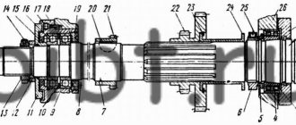
Rice. 8. Fastening with an anchor bolt
As indicated, such foundations serve only as a basis for machines. Their role is usually played by the cement floor of the workshop or a concrete base on which a wooden block is laid. It is not recommended to install the machine directly on a checker, since the machine is difficult to align, alignment is quickly disrupted, the machine is unstable, warps and deforms. There is no justification for the long-term violation of this provision at a number of factories, where many machines are placed directly on the end block, while knocking them down with wooden wedges. Wedges are often splintered and crushed by the machine. The installation is disrupted even more quickly when emulsion gets on the floor, which to some extent always occurs in industrial conditions.
In multi-storey buildings, the installation of machines is also carried out on inter-storey floors, which, of course, is less desirable and requires additional calculations [4].
The foundations of the first group also include separate rigid slabs, on which the machine can be quickly aligned and which reduce the specific pressure on the ground. The minimum depth of the foundation of such slabs, reaching dimensions of 4x4 m 2, is determined by the depth of the plant layer of soil. Their relatively low weight allows them to be made mobile. With all movements of the machine that occur during the redevelopment of the workshop, the slab is moved along with it. This makes the work much faster and cheaper.
When designing all foundations for machine tools, similar to the practice of construction design in general, first, for structural reasons, acceptable dimensions of the foundation are outlined, and then a verification calculation is made. The calculation of the foundation slab consists of several stages.
First stage . The contour and dimensions of the slab are outlined in plan, based on the shape and dimensions of the machine sole. In this case, the contour is simplified as much as possible. In addition, the slab must be designed so that the weight of the machine with the slab is distributed as evenly as possible on the ground, i.e., so that the resultant force of gravity is applied centrally.
The indicated provisions of the first stage are valid not only for rigid slabs (foundations of the first group), but also for foundations of the second group.
Technical conditions for the manufacture of the foundation.
For normal precision machines: Soil bearing capacity 5kg/m2. If necessary, load the foundation with an additional load (concrete blocks, blooms, etc.) exceeding the weight of the machine by 3-4 times and check the elevation marks with a level on a benchmark not connected to the foundation every day until the end of shrinkage. For high-precision machines: The foundation must be made with free side edges and heavy concrete of design grades must be used with a compressive strength of 150-200 kg/cm2. To fill the foundation, use a concrete mixture with a volume ratio of cement-sand-crushed stone of 1:1:3 (concrete grade not lower than M250). Foundation depth H > 0.6 √F, where F is the area of the foundation. The foundation is reinforced with a single lattice along the length, width and height with a cell size of 200 mm. The diameter of the reinforcement depends on the size of the foundation and can be from 12 mm to 20 mm. Strength of foundation concrete. Installation of the machine can be allowed when the concrete reaches a compressive strength of at least 50% of the design strength (approximately corresponding to seven-day concrete). By the time the machine is started, the concrete strength should be at least 70% of the design strength (approximately equivalent to 15-day concrete). The period for complete hardening of concrete is 28 days. The quality of concrete is controlled by the strength of control cubes 200x200x200 mm. The strength of concrete in a finished foundation can be roughly estimated by sound and impact.
Overview and diagrams of common models
Among the diverse model range and several generations of machines that are produced by our production, there are several models that continue to be popular for their technical characteristics and universal properties.
All of them are used in production or in domestic conditions to this day. At the same time, they continue to be worthy competitors to foreign analogues.
These are reliable, durable and durable devices capable of performing a huge number of different functions.
1L532
One of the most popular machines in the former USSR, which can successfully process workpieces of medium and large sizes.
At one time, this equipment was successfully exported to many countries around the world. Accuracy class – N. Machine weight – 43 tons.
16U04P
High precision equipment. The largest diameter of the part processed above the bed is 200 mm. Machine weight – 750 kg.
1P611
Lathe 1I611, used in production, including for turning wheels of railway vehicles. According to GOST, they are distinguished by increased accuracy and have the ability to brake the spindle. Device weight 560 kg. Easily performs the following functions:
- Drilling.
- Segment.
- Cutting internal and external threads.
- Treatment of various surfaces.
The largest diameter of the workpiece above the bed is 250 mm.
1D601
This machine is better suited for purely domestic use. The accuracy is lower than the previous machine. It features high performance even after many years of operation.
Moving the caliper is only possible manually. The weight of the entire machine is about 30 kg. Due to the small dimensions, the maximum length of the workpiece to be processed is 18 cm.
16K40
One of the most popular models that has really gained popularity among craftsmen. Belongs to the middle class of equipment with accuracy class N.
Since 1932, several tens of thousands of various screw-cutting lathes have been produced in the USSR. They were used not only in production, but also for training young people, in schools, colleges, and many had desktop machines in garages, homes, and their own workshops.
Selecting a location for installing the machine
In most cases, machines are installed in such a way as to provide free access to it from any side. Machines that process large-sized workpieces are located close to transport routes or directly under lifting devices. This allows finished products to be transported to the warehouse without the risk of damage, since there is no intermediate transportation step.
An important point is also the proximity of the electrical distribution panel. The closer the machine is located to the distributor, the shorter the electrical cables. In this case, they do not interfere with the movement of personnel and vehicles around the workshop. Sometimes the cables are laid in special patterns made in the floor and covered with steel sheets. If the enterprise uses a system for centralized supply of cutting fluid, then hoses through which coolant is supplied to the machines are also placed in these patterns.
Scheduled preventive maintenance
PPR (scheduled preventive maintenance) - implies all actions to maintain the operating power of the lathe. When caring for the equipment, its technical characteristics will correspond to those stated in the passport.
For each lathe, you need to draw up a schedule that will take into account the data stated in the passport and the features of the operating mode. The schedule must clearly indicate the intervals between maintenance work (lubrication, cleaning, oil control), replacement of unsuitable parts and the unit washing system.
Also, the equipment plan includes preventive, current and major repairs. Moreover, it is necessary to include both small and medium-sized ongoing work.
When should maintenance and repairs be carried out?
All manufacturers of turning equipment indicate the following work in terms of maintenance:
- Compliance with the rules for operating machine control mechanisms.
- Proper organization of the workplace with restrictions.
- Monitoring the cleanliness and integrity of the lubrication system and containers.
- Monitoring the oil level in equipment.
- Elimination of minor breakdowns.
- Adjustment of different machine systems.
All these duties do not require a separate day, they are carried out quickly and can be done during lunch breaks or when transferring work to another shift. It is better to readjust the lathe on a day off. If there is a specialist on staff with permission to set up equipment, then he can easily cope with such a task. If there is no such thing in the staff, then it is better to delegate the adjustment of equipment to the responsibilities of the repair and commissioning team.
Part of routine maintenance includes daily maintenance to clean and adjust the machine after the job is completed. If the enterprise operates in several shifts, it is recommended to carry out maintenance work every 8 hours.
It is also worth considering that in an enterprise that uses lathes and a shift work schedule, the staff must have a repair and commissioning team, which includes mechanics, lubricants, electricians, saddlers and mechanics. It is this team that will be responsible for the performance of the equipment and the quality of the products produced.
Final moments of lathe installation
After assembling the machine (if necessary) and installing the machine on the foundation or table, tighten the anchor bolts. It is also important to evaluate the specifications specified for pulling out anchor bolts from the foundation. As a rule, about 25% of this value should be discarded to ensure maximum installation strength. Modern machine tool manufacturers make fastening bolts from stainless metals or using special galvanized coatings. It also wouldn’t hurt to additionally treat the anchors with anti-corrosion material, especially in places where moisture may appear.
After installation and sequential tightening of the anchors, you should once again additionally measure all surfaces of the machine with a level to ensure that there are no irregularities or distortions. If you have any questions about installation and require additional explanations at the work site, we are always happy to provide installation supervision services. Our specialists will come to you and give detailed advice on the correct installation of the machine at each stage of work.
Regulations for arrangement
Above we discussed the basic requirements that any foundation intended for installing industrial equipment on it must satisfy. However, there are other requirements - for the foundation for equipment with dynamic loads, which it must meet.
Design work, as well as the practical part of arranging the foundation, should be carried out only by competent specialists who, in addition, also have experience in carrying out this type of work. In order to create a correct and complete project, it is necessary that all the required data is available. During the construction of the foundation for the equipment, it is necessary to periodically carry out quality control. It is very important that the actions of all participants in the work process are strictly coordinated. Those foundations that have already been erected should be used only with the equipment for which they are intended. There is technical documentation for this. For construction, you can use only those materials that are suitable according to the design documentation. In the future, it is necessary to carry out maintenance of the foundation so that the structure can be used for as long as possible. It is recommended to use the simplest possible parts as fastenings.
For example, these could be anchor bolts that are embedded in concrete.
Lathe installation
To install the machine, it is necessary to install a concrete foundation 30 days before operation. The calculation of the installation height of the lathe must be in accordance with the Operating Manual. If necessary, our company’s specialists will install the lathe on vibration supports.
The range of services for installation of a lathe also includes the following work:
- Assessment work at the installation site;
- Calculation of the foundation for a lathe;
- Drawing up installation drawings;
- Pouring the foundation for the machine;
- Leveling equipment with a level;
- Installing the lathe on the foundation.
Sharpening tool
For abrasive sharpening of the cutter, a sharpening machine or lathe can be used. For carbide tools, green carborundum of medium hardness is used. For initial processing, the abrasive value of the wheel should be 36-46, at the end of the process - 60-80. For high quality sharpening, a whole circle is required, without defects and geometry violations.
Diamond wheels are also widely used for sharpening turning tools, which ensures high cleanliness of cutting surfaces. In comparison with carborundum wheels, the surface cleanliness of the cutter increases by two classes, and work productivity increases. The use of diamond wheels also increases the service life of the tool - the possible number of cutter regrinds increases by 20-30%. But it should be taken into account that it is economically feasible to use sharpening with a diamond tool with an allowance of no more than 0.2 mm. For larger values, preliminary sharpening with a carborundum wheel is recommended.
Procedure for correct installation of a lathe
Depending on the size of the machine - small, household, medium power or massive industrial, installation can be done either on a table in the first case, or on a pre-created concrete foundation in the second case. In each of the options, the main thing is to measure with a level all possible deviations from the plane and eliminate them as much as possible. When installing the machine on the floor, on a concrete foundation, it is secured with an additional layer of mortar in the places of the legs and shoes.
In addition, you need to take care in advance about the presence of special rubberized gaskets that additionally shock-absorb the machine. As a rule, in most configurations, they come from the manufacturer in packaging, but from experience it is noted that having additional ones never hurts.
Why vibration support is a bad option
The foundation of the machines is, as a rule, 1-2 or more meters of concrete, in which anchor bolts are fixed. The machine is leveled and then firmly screwed to the foundation. In this case, the tightening torque of each support affects the overall geometry of the machine. Therefore, the installation of a machine requires a very highly qualified specialist - a commissioning operator, who understands how the machine behaves when tightening or loosening a particular attachment point. When installed correctly, the machine has an ideal geometry, and the rigidity of the foundation increases the rigidity of the machine. As a result, processing accuracy is increased and wear on the machine guides is minimized. If vibration supports are used, the machine bed “walks” under load, which negatively affects both the quality of the manufactured part and the service life of the machine itself.
Construction of foundations for technological equipment: general rules
The construction of a foundation for industrial equipment involves the construction of a structure with original qualities, namely:
- Significant mass - the greater the weight of the base, the higher the vibration resistance.
- Increased strength - the higher the resistance to static and dynamic loads, the longer the service life of both the foundation itself and the equipment mounted on the base.
- High resistance to aggressive environments - the higher the inertia of at least the upper layers of the foundation, the longer it will serve as a base for a machine or mechanism.
Moreover, these characteristics are complemented by minimum tolerances on the dimensions of the foundation. That is, not only the bolts with which the equipment is installed on the foundation should be in their “right place” - deviations from the calculated dimensions (length, height, width) should be kept to a minimum.
There should be no slope of the grillage in principle. Otherwise, the operating loads will be distributed unevenly, which will reduce the service life of both the base and frame of the mechanism.
Types of base designs
Such a set of characteristics can only be provided by the following types of foundation designs:
- Baseless base of slab type, dampening vibration with its mass. Such foundations can be poured into formwork only on the first floor of the workshop. Such a design will cost a significant amount, since the maximum amount of building material is spent on the construction of a solid slab-type base. However, the largest machines and mechanisms are mounted only on such foundations.
- Basement base-floor, mounted on the second floor and above. Such a foundation dampens vibration, transmitting vibrations to the frame of the workshop itself (through contact with the interfloor ceiling). In essence, it is the same slab, only not poured, but assembled from reinforced concrete products installed on the interfloor floor beams. Such a base can only withstand static loads or vibration with minimal amplitude.
- Wall foundation, developing the idea of a strip foundation. The load-bearing load and vibration in this case are taken by load-bearing walls or internal partitions. As a rule, such foundations are placed under mechanisms located on the second floor of the workshop.
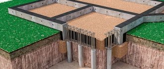
- Frame type bases (with beam grillage). This design withstands high-frequency vibration. Therefore, in most cases, foundations for impact mechanisms have a “frame” design. After all, dampers can be installed in the frame supports to dampen vibration.
Types of bases
To install the units, different foundation structures are used that meet the requirements set by the standards.
In practice, machines are installed mainly on the types of support structures presented in the table below.
| № | Type of foundation structure | Characteristics of the constructed base |
| 1 | slab foundation without basement | it is poured only on the ground floor, it is expensive due to the significant consumption of building materials and high labor costs, but its massiveness well dampens the resulting vibrations |
| 2 | frame base equipped with a grillage of beams | is capable of withstanding high-frequency vibrations without negative consequences, therefore it is often used for the installation of impact mechanisms |
| 3 | wall support structure (is a modification of strip-type bases) | it is erected from the second floor, the effective load from the units with this support structure is taken by the external (load-bearing) walls, as well as internal partitions |
| 4 | base-floor with a basement | is located above the first floor, transmits vibrations (arising during the operation of machines) to the interfloor floors (building frame), and is capable of withstanding only static loads or vibrations with insignificant amplitude |
The most modern option for light or medium-heavy mechanisms is to install bases with springs or other types of vibration supports that dampen vibrations that occur during operation of the units. Dampers (vibration dampers) can be especially easily installed under frame-type bases.
At its core, a floor foundation equipped with a basement is the same slab, only built from ready-made reinforced concrete blocks laid on floor beams.
The given foundation structures are divided into 2 types:
- basementless (it almost completely lacks a part located above the floor);
- basement (with a well-developed above-ground section).
The latter option can have a wall or frame form. It is characterized by a large height above the floor plane.
Foundations by design can also be prefabricated, monolithic, prefabricated-monolithic. They come in the following forms:
- rectangular;
- tape;
- stepped;
- shaped;
- trapezoidal.
It is possible to use piles of different types as foundations for units with periodic loads. A slab or strip grillage is installed on top of the supports. Impact-type mechanisms must be mounted on solid reinforced concrete piles.
The distances between installed pillars are regulated by SP 24.13330. It should not exceed 10 of their diameters. The vibrations of pile foundations can be calculated using the relevant subsections of this document.
Various blocks and slabs (hollow or solid) are used as elements of prefabricated structures.
Individual and group foundations
The equipment is mounted on individual or group foundation structures.
Group foundations are designed for installation of several mechanisms of light or medium weight (up to 8 tons) with a rigid frame and normal operating accuracy, operated with a predominance of static forces. Their thickness is usually 150-250 mm. They often serve only as bases. The single support is mainly concrete (or reinforced concrete) floors. But in practice there are other design options.
Mechanism frames are considered rigid when the ratio of their length to height is no more than 2 to 1.
Individual type foundations are built for precision equipment with medium or heavy weight, which operates with dynamic loads of moderate or significant magnitude. Such supports, in addition to removing vibrations from machines and ensuring their correct working position, also isolate the units from each other. This prevents the transfer of vibrations between them.
Lightweight machines, or medium-weight units with a predominant static type of load, are often mounted directly on the floor or interfloor ceiling (the so-called foundation of the first type). If necessary, such a base is reinforced with a concrete screed (while laying reinforcement), also increasing its thickness.
Machine installation
In previous years, if not eras, a typical machine was a monoblock structure that only needed to be lowered onto the foundation, leveled and secured. Now the situation has changed somewhat. A modern machine tool is often an entire machining center, consisting of both a main functional monoblock (the machine itself) and many attachments, which include the following:
- automation;
- hydraulics;
- measuring devices;
- service devices.
The specified equipment is usually supplied in separate boxes or boxes. Thus, the task of the installers is not only to install the machine, but also to assemble all the attached elements.
How to build it yourself
A normal machine costs at least 50,000 rubles. If you assemble it yourself, this amount will be significantly reduced.
Attention. To make a homemade lathe, it is advisable to use standard drawings
There are all the dimensions of the parts and the order of assembly.
These drawings can be improved. For example, it is worth adding an emergency shutdown button, a thermal relay that protects against overheating, and a protective casing.
Selection of parts
Certain elements of the device will have to be purchased assembled, such as the motor and clamp. Some are purchased separately and ordered in workshops, where they will be made to the required dimensions. The better the steel used, the longer the machine will last.
Base
The best choice would be to use a cast frame from an old non-working machine. The stability of the unit depends on the base. As an alternative, you can weld a frame from channels or profile pipes. You cannot take wood, as it will not be able to withstand the workload.
Electric motor and transmission
For the engine, you can use a device from an old washing machine or other household appliances that have sufficient power. It is also worth considering purchasing a new engine, since the price is not too high.
It is better to use a belt drive. It is much easier to assemble. Also, when using a belt directly on the shaft, there is less impact, and this significantly increases the service life.
Master and slave centers
These two nodes are placed on the same axis. There is also a type of machines that have one leading center. The follower must be placed on the tailstock (it can be rotating or stable). The sharpened end of the bolt is suitable for manufacturing.