Assembling the unit and adjusting the spindle supports of the 1K62 lathe.
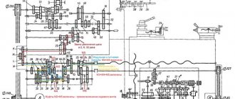
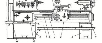
An example of assembling the unit and adjusting the spindle supports of a 1K62 lathe is shown in Fig. 101.
Rice. 101. Assembling the spindle of a lathe 1K62
The assembly of the spindle assembly begins after careful preparation and checking of all connections and parts of the spindle for compliance with the drawings and specifications.
First, assemble the rear spindle support. A seal (cuff) 15 is installed in the sleeve body 18, followed by an angular contact ball bearing 16. It is installed so that the thinnest end of the outer ring of the bearing is directed towards the seal 15. Then an intermediate ring 10 and bearing 9, which has a thin the end of the outer ring should be facing in the opposite direction from the ring 10. The bearings are secured with a nut 19 and the nut is locked with a screw 8.
A roller bearing 3 and a ring 5 are installed on the spindle 2; then screw nut 6 until it comes into light contact with ring 5 and lock with screw 25.
Next, the spindle is inserted into the housing 26 through a hole in its front wall, a double-rimmed gear 22 with a sleeve 24 secured by a spring ring 23 is pushed onto the spindle. Then a key 20 and a gear 21 are installed in the groove of the spindle. After this, the end of the spindle is inserted into rear support and install the front support into the housing hole. In this case, the outer ring 4 of the bearing 3 is slightly shifted towards the housing and when the spindle is finally installed, this ring is installed so that it is located at the level of the inner ring of the bearing.
At the second end of the spindle, screw 17 is secured and rings 11 and 12 are installed, nut 13 is screwed on and tightened with a wrench until the spindle is in place, which is determined by the tightening force and the rotation of the spindle. Having installed the unit, the wheel 21 is finally mounted on the spindle and the stopper 7 is screwed in. The assembly is completed by fastening the flange 1.
After assembly, adjust the spindle supports. Begin adjustment from the rear support. Having unscrewed nut 13 a little, turn the spindle so that the inner rings of the bearings take the correct position (the spindle should rotate easily). After this, screw in the locking screw 14. The front support is adjusted by screwing in the nut 6. The inner ring 3 of the bearing slides onto the cone of the spindle neck. At the same time, the ring slightly increases in diameter and due to this, the radial clearance decreases.
Nut 6 should not be tightened too much, as the inner ring may loosen so much that the rollers will become pinched. Therefore, adjustments must be made carefully, checking the spindle for ease of rotation.
After adjusting the spindle supports, check the clearances. The axial clearance is checked with a special device.
Method for adjusting the tension in angular contact bearings of the spindle assembly
METHOD OF ADJUSTING TENSION IN angular contact bearings of a spindle assembly, which consists in the fact that the outer race of one of the bearings is moved in the axial direction by a calculated value, which is different in that, in order to increase the durability of the spindle assembly by eliminating deformation of the race during its axial movement, before the axial movement of the race of one of the bearings, an axial force is applied to the spindle to unload this bearing, and after the axial movement of the race, the axial force applied to the spindle is removed. UNION OF SOVIET
SOCIALIST
REPUBLIC (19} (11) g 1} V 23 V 19/02
DESCRIPTION OF THE INVENTION
FOR THE AUTHOR'S CERTIFICATE
° а\а\ (STATE COMMITTEE OF THE USSR
ON AFFAIRS OF INVENTIONS AND DISCOVERIES (21) 3509074/25-08 (22) 11/12/82 (46) 06/23/84. Bull. F 23 (72) E.V.Korgichev. (71) Ukrainian Research Institute of Machine Tools and Tools (53) 621.941.2 (088.8) (56) 1. Copyright certificate of the USSR
11} 415097, cl. B 23 B 19/02, 1970 (prototype). (54)(57) METHOD OF ADJUSTING TENSION
IN RADIAL CONTACT BEARINGS
SPINDLE UNIT, consisting in the fact that the outer race of one of the bearings is moved in the axial direction by a calculated amount, characterized in that, in order to increase the durability of the spindle assembly by eliminating deformation of the race during its axial movement, before the axial movement of the race of one of the bearings to the spindle an axial force is applied to unload this bearing, and after the axial movement of the cage, the axial force applied to the spindle is removed.
1 10
The invention relates to machine tool construction and can be used in multi-operational machines, the high-precision spindle units of which are made with remotely controlled tension in the bearings.
A spindle head with hydroduplexing of angular contact bearings is known, which implements a method for adjusting the tension, which consists in moving the outer race of one of the bearings in the axial direction by a calculated amount (11.
The disadvantage of this known method is the reduced durability of the spindle assembly, caused by intense wear of the connection between the spindle assembly housing and the moving bearing race. Intense wear occurs when the cage moves axially by a calculated value corresponding to large tension values, since the cage is deformed under the influence of increasing forces of interaction with the balls and increases in diameter. As a result, the installation gap established during assembly between the holder and the body of the high-precision spindle assembly (2-6 μm) is reduced to a negative value, significantly increasing the friction forces that prevent the axial movement of the holder.
The purpose of the invention is to increase the durability of the spindle assembly by eliminating deformation of the cage during its axial movement.
This goal is achieved by the fact that according to the method of adjusting the tension in the angular contact bearings of the spindle assembly, which consists in the fact that the outer race of one of the bearings is moved in the axial direction by the calculated amount, before the axial movement of the race of one of the bearings is applied to the spindle axial force to unload this bearing, and after axial movement of the race, the axial force applied to the spindle is removed.
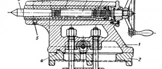
The drawing shows a spindle assembly designed to implement a method for adjusting the tension in angular contact bearings.
The spindle assembly consists of a housing 1, a spindle 2, angular contact bearings front 3 and rear
4 supports Bearings are mounted on
98671 2 spindle and inserted into the housing. An actuator is also mounted in the housing, which in the simplest case can be made, 5 for example, in the form of a self-braking wedge mechanism containing a contacting pair of rings 5 and 6 interacting with the movable cage 7 of the rear support 4, and the contacting surfaces of the rings 5 and 6 are made flat at an angle to the axis other than 90, and the ring 5, which interacts with the displacement mechanism, is installed with the ability to move in the radial direction. The displacement mechanism is made in the form of a hydraulic cylinder 8 with a stop 9. A pin 10 is placed in the bore of the spindle 2.
The method of adjusting the tension in
20 angular contact bearings of the spindle assembly are carried out as follows.
At the lowest value of the adjusted tension in supports 3 and 4, equal to 100 kgf, ring 5 with a bevel is in the position fixed in the drawing ° The spindle unit (SHU) with this value of the adjustable tension is adjusted to work at high speeds (4000-5000 rpm ) for finishing operations.
The gap between the outer ring 7 of the support 4 and the housing 1 is equal to the installation value (3 μm).
When readjusting the control unit to operate at lower speeds (10,002,000 rpm) to carry out rough technological operations, the maximum tension of 400 kgf is remotely set in supports 3 and 4.
4О To do this, go to pin 10 of the spindle
2 apply an axial tool change force P c = 800 kgf. This force is applied by a special mechanism (not shown), which is structurally included in multi-operational machines.
Under the influence of a force Po = 800 kgf, support bearing 3 is loaded and support bearing 4 is unloaded. A gap of about 20 μm is established in support bearing 4. The diameter of the outer race 7 of bearing 4 decreases slightly.
Next, the special executive
And with a device in the form of rings 5 and 6, the outer race 7 of the support bearing 4 is forcibly shifted towards the support bearing 3 by the calculated value. Compiled by G. Nikogosova
Techred S.Iigunova. Proofreader I. Erdelyi
Editor S. Pekar
Order 4306/7 Circulation 1037 Subscription
VNIIPI of the USSR State Committee for Inventions and Discoveries
113035, Ioskva, Zh-35, Raushskaya embankment, 4/5
Branch of IIIHI "Patent", Uzhgorod, st. Proyektnaya, 4
E 10986 well 25 microns, corresponding to the highest value of the adjustable tension, equal to 400 kgf. To do this, oil is supplied under pressure from the control system (not shown) into the cavity of the hydraulic cylinder 8. The hydraulic cylinder piston moves away from the housing 1 to the stop 9. The ring 5, moving with its bevel, moves the ring 6 with the outer race 7 towards the bearings 1O of the support 3.
The outer ring 7 moves freely without deforming, and therefore without changing its diameter.
By this time, the tool change in spindle 2 is technologically completed and the force P = 800 kgf is removed, causing spindle 2, under the action of the elastically deformed bearing of the front support 3, to shift to the bearing of support 4, the outer race of which 7 is in the position corresponding to the highest value of the adjustable tension, equal to 400 kgf.
The displacement of the spindle 2 onto the support 4 is accompanied by an increase in the latter tension to a calculated value of 400 kgf, and an increase in the diameter of the outer race 7 to a value at which the gap between the race 7 and the body 1 is set equal to
1-3 microns. The diameter of the cage practically does not increase any further due to the high rigidity of the joint between the cage 7 and body 1.
71 4
With this method of adjusting the tension in the process of moving the cage by a calculated value corresponding to large values of tension, the gap between the moved cage and the control unit body remains unchanged, since the diameter of the cage does not increase. The diameter of the race does not increase due to the fact that before the bearing race moves, the latter is unloaded by applying an axial force to the spindle. There is no interference in the bearing with a movable race. This means that there are no forces of interaction between the balls and the holder, which change when the holder is moved using the existing method. leads to a change in the diameter of the holder.
The diameter of the cage increases only after it moves and stops as a result of removing the axial force on the spindle, since in this case interference appears in the bearings, and hence the interaction forces between the balls and the cage, increasing its diameter by an amount exceeding the installation gap.
Since in the process of moving the holder it is not deformed, the gap between it and the body does not change and remains equal to the mounting one.
As a result, additional frictional forces do not appear and there are practically no friction forces in the connection between the cage and the body.
Information about the manufacturer of the screw-cutting lathe 16K20
The first universal screw-cutting lathes with a gearbox for the first time in the USSR began to be produced at the Moscow Machine Tool Building named after. A.I. Efremov in 1932 and received the names DIP-200, DIP-300, DIP-400, DIP-500 ( DIP
- Catch up and Overtake), where 200, 300, 400, 500 is the height of the centers above the frame.
Machine tools produced by the Moscow Machine Tool Plant Krasny Proletary, KP
History of the series of screw-cutting lathes from DIP-200 → 1a62 → 1k62 → 16k20 → MK6056
In 1930, the Moscow Machine Tool Plant decided to develop a new standard lathe, abbreviated as TS. Somewhat later it was renamed DIP-200 - Let's Catch Up and Overtake
, according to the main slogan of the first five-year plan, where 200 is the height of the centers above the frame.
from the German company VDF was chosen as a prototype .
In April 1932, preparations began for the release of the first batch of DIP-200 machines. On April 25, 1932 , the first Soviet universal screw-cutting lathe with a gearbox, DIP-200, was assembled and tested. By the end of 1932, 25 DIPs were produced.
In 1934, production of machines DIP-300, DIP-400, DIP-500 was mastered. Subsequently, the production of these machines was transferred to the Ryazan Machine Tool Plant. The production of the DIP-500 machine was also transferred to the Kolomna Heavy Machine Tools Plant KZTS.
In 1937, ENIMS developed a type (nomenclature of types and sizes) of machine tools and adopted a unified system of machine symbols. According to the new designation system, the first DIP-200 became known as 1D62
. But the abbreviation DIP-200 has been preserved to this day - to designate a lathe with a center height above the bed equal to or close to 200 mm.
In 1940, the plant produced the 162K (26A) machine - one of the DIP-200 variants.
In 1945, the plant switched to production of the modernized DIP-200 machine (DIP-20M, 1d62m).
In 1948 , the plant switched to production of the 1A62 machine.
In 1949-1953, without stopping production, the transition to continuous production of the 1A62 lathe was carried out. Also produced over the years: 1620, 1B62, 1m620, 1622.
In 1954 , a prototype of the 1K62 , mass production of which was launched in 1956.
In 1956, the plant switched to large-scale production of the new 1K62 machine. Over the next 18 years, during which they were manufactured, 202 thousand of these machines were produced.
Modifications were produced based on the 1k62 screw-cutting lathe: 1k625, 1k620, 1k62B with increased accuracy, etc.
In 1965, the plant produced a high-precision screw-cutting lathe 16B20P, which became a transitional model between 1k62 and 16k20. The feed box 16B20P.070.000 and the apron 16B20P.061.000 of this machine became the standard for all subsequent models of this series.
In 1971 16K20 machines was manufactured ; in 1972, at the Leipzig Fair, the 16K20 machine was awarded a gold medal.
In 1972-1973, the plant was reconstructed in connection with the release of a new model of the 16K20 machine. Serial production of these machines is being mastered. By the end of the year, up to 1,000 such machines come off the assembly line per month. About 10 percent is exported.
Based on the basic model of the 16K20 screw-cutting lathe, many modifications were made, including: 16K25, 16K20M, 16K20P, 16K20V, 16K20G, 16K20K, 16K20F1, 16K20PF1, 16K20VF1, etc.
In 1988, production of the 16k20 machine was discontinued. It was replaced by screw-cutting lathes of the MK series: MK6046, MK6047, MK6748, MK6056, MK6057, MK6758.
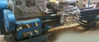
General view of the screw-cutting lathe 16K20
Photo of a screw-cutting lathe 16k20
Photo of a screw-cutting lathe 16k20
Photo of a screw-cutting lathe 16k20
Location of controls for screw-cutting lathe 16K20
Layout of controls for a 16k20 lathe
Gearbox of screw-cutting lathe 16k20
List of controls for screw-cutting lathe 16K20
- Handle for setting the feed rate and thread pitch
- Handle for setting the type of work: feed and type of thread being cut
- Spindle speed setting handle
- Handle for setting normal, increased thread pitch and position when dividing multi-start threads
- Input circuit breaker
- Signal lamp
- Electric coolant pump switch
- Machine load indicator
- Handle for setting right and left threads
- Handle for setting the spindle speed range
- Main drive friction clutch control handle (interlocked with handle 17)
- Local lamp switch
- Handle for rotating and securing the indexable cutting head
- Handle for manual movement of the tool slide of the caliper
- Handle for attaching the tailstock quill to the bed
- Tailstock quill movement flywheel
- Main drive friction clutch control handle (interlocked with handle 11)
- Lead screw nut on/off handle
- Handle for controlling mechanical movements of the carriage and cross slide of the caliper
- Push-button station for turning on and off the main drive motor
- Handle for manual movement of the cross slide of the caliper
- Handwheel for manual carriage movement
- Button for lubrication of the carriage guides and cross slides of the caliper
- Handle for setting the feed rate and thread pitch and turning off the feed mechanism when cutting threads directly
- Tailstock quill clamp handle
Table of threads and feeds of a screw-cutting lathe 16k20
Table of threads and feeds of a screw-cutting lathe 16k20
The table is shown for the basic version of machines with spindle speed limits per minute of 12.5..1600. The table is placed on the spindle head of the machine.
Handles 1 and 2 select the spindle speed in the range from 12.5 to 1600 rpm. 4 positions of handle 1 and 6 positions of handle 2 - allow you to get 24 speed values. As can be seen from the table, the speed values of 500 and 630 rpm are repeated
Handle 3 controls the link for increasing the feed pitch or thread in the spindle head in a ratio of 1:2, 1:8, 1:32, depending on the number of spindle revolutions.
16K20 (1)
Ministry of Education and Science of the Russian Federation
FSBEI
HPE TSTU
Department: TM, MS and I
Laboratory work “Adjustment and adjustment of turning-screw-cutting
machine model 16K20"
Completed:
student of group STM-41
Checked:
Kolodin A.N.
Tambov 2013
Goal of the work:
study the design, principle of operation, kinematics and control of the screw-cutting lathe mod.16K20 and its main components, acquire practical skills in calculating machine settings for various types of work, and become familiar with its technological capabilities.
Tasks:
- Study the structure and operation of the machine and its components, kinematic diagram.
- Familiarize yourself with the procedure for setting up a machine to perform various turning operations (cutting threads of various types, machining conical surfaces, machining holes).
- Configure the machine to perform turning operations specified in the application table.
Guidelines
1. Purpose of the machine
and its individual components
The screw-cutting lathe mod. 16K20 is designed for processing external and internal surfaces of rotation, cutting threads of various types on them (metric, inch, modular, pitch, etc.) shaped and end surfaces, turning grooves, cutting and cutting Archimedean spirals at the ends.
General view of the machine
2.Technical characteristics of the machine mod.16K20
The largest diameter of the part installed above the frame, mm - 400
Distance between centers, mm………………… 710,1000 and 1400
Spindle hole diameter, mm. . ……………………..………52
Number of spindle speed values ……………………24
Spindle rotation speed, rpm………………….12.5+1600
Feeds, mm/rev: longitudinal …………………… 0.05-2.8
transverse………………………………………………………………. 0.025-1.4
Thread pitch: metric, mm. . …………………….0.5-112
inch (number of threads per I")……….56-0.25
modular, module …………………………. 0.5-112
pitch, pitch…………………………56-0.25
Electric motor power, kW……………………… 10
3. Block diagram of turning group machines
Lathes of the turning group are designed for processing the external, internal and end surfaces of rotating bodies and cutting threads (screw-cutting lathes). Turning cutters are used as tools. Dimensional tools can also be used: drills, countersinks, reamers, taps, dies, etc.
The surfaces of bodies of rotation on lathes are obtained according to the scheme “trace” + “trace” or “trace” + “copying”. The first is the method of obtaining a guide, and the second is the generatrix of generating lines.
This implies the need to have in lathes a rotational movement of the workpiece B1 and a translational movement of the cutter P2 along the axis of rotation of the workpiece and P3 - perpendicular to its axis of rotation when turning the end surfaces. Moreover, to ensure the possibility of cutting threads with cutters, it is necessary that the movements of B1 and P2 be coordinated. Based on these considerations, the block diagram of a screw-cutting lathe can be presented as follows
Simple longitudinal turning is carried out by the implementation of two executive movements F (B1) and F (P2); end - F (B1) and F (P3). Thread cutting is carried out by one complex executive movement (two-element) F (B1 P2). The coordination of the elementary movements B1 and P2 is carried out by the internal kinematic connection B1→2→P2→ir→icp→3→4→t1→P2. The use of two parallel gears “screw-nut” and “gear-rack” is due to the following. When cutting threads, greater connection accuracy is required (B1 P2), for which a screw-nut transmission is used as it is more accurate. During normal turning, in order to avoid wear of the “screw-nut” pair, it includes a rack and pinion gear.
4. Main components of the machine and machine controls
The machine consists of the following main components.
Main nodes:
1 — front cabinet; 2- belt drive; 3 — feed box; 4 — gearbox (guitar); 5 - spindle head; 6 — push-button station; 8 - bridge; 9 — lunette; 10 — caliper; 11 — tool holder; 12 - apron; 13 — protective screen; 14 - tailstock; 15 - bed; 16 - base; 17 — upper support (slide); 18 — lead screw; 19 — running shaft; 20 - spindle.
The bed serves as the basis for fastening the fixed components of the machine, to maintain the accuracy and rigidity of their relative position. The bed guides ensure the straightness of the longitudinal movement of the caliper carriage and tailstock. The headstock is used for
spindle mounts. The workpiece is supported and secured using various types of chucks, centers, mandrels or special fixtures. In the headstock there are gearbox mechanisms, which serve to change the spindle rotation speed, both in the forward and reverse direction of its rotation. A set of interchangeable gears is used to adjust the type and pitch of the thread. The feed box is used to change the feed amount, to adjust the type and pitch of the thread being cut. When cutting precise threads, the feed box is switched off. The support is used for fastening the cutter and for carrying out feeds: mechanical longitudinal or transverse and manual at an angle to the axis of the machine when processing short cones. The transformation of the rotational movement of the lead screw or lead roller into the translational movement of the support is carried out by the mechanisms of the machine apron. To turn cones with a short generatrix length, the tool holder guides are rotated by the angle of the cone. The tailstock is used to create a second support for the workpiece when processing parts, to fasten drills and impart axial feed to them, to shift the rear center from the axis of rotation for the purpose of turning flat cones.
Controls:
21, 35 — handles for engaging the friction clutch of the main movement drive; 22,23,24 — feed box adjustment handles; 25.7 — spindle speed adjustment handles; 26 — adjustment handle for thread pitch (normal or increased); 27 — handle for turning on the right or left thread; 28,29,31,33 — handwheels for manual movement of the caliper, cross slide, tailstock quill; 30 — handle for turning on automatic feed; 32.34 — quill and tailstock clamping levers.
5.Setting the main movement of the machine
The machine's gearbox consists of two kinematic chains.
Low spindle speeds are transmitted when enumeration is enabled along the circuit:
High spindle speeds are transmitted when the search is turned off through the circuit:
The search has the following gear ratios
Setting up the machine for processing conical surfaces
Method for processing conical surfaces.
- Wide incisors. Grinding is carried out with a cutter, the main cutting edge of which is set at an angle to the axis of the workpiece. The method is applicable for short cones (l≤15+20 mm). The processing scheme is shown in Fig.a.
- With the rotation of the upper slide (Fig.b). Conical surfaces with large apex angles are processed. When setting up, the upper slide of the caliper is installed at an angle α along the divisions on the flange of the rotating part of the caliper. The machine does not have a mechanical feed of the upper slide, so the feed is carried out manually by rotating the flywheel. In this case, it is difficult to obtain low roughness of the machined surface.
- Transverse displacement of the tailstock housing.
This method is used to grind long surfaces with a small cone angle. The displacement value h (Fig.c) of the tailstock is calculated using the following formulas: h=(Dd/2)∙(L/l) h=L tgα
Processing is carried out with longitudinal feed of the caliper. The accuracy of the method is relatively low.
Note
. Other methods of processing conical surfaces are also widely used, such as;
a) using a universal carbon ruler;
b) using special copying devices, for example, hydrocopying supports;
c) simultaneous activation of longitudinal and transverse feeds;
d) on computer-controlled machines.
However, the listed methods require special equipment for lathes (copy ruler, hydraulic support, etc.) or machines with wider technological or kinematic capabilities (methods “c” and “d”).
Scheme for processing conical surfaces
Adjusting threading machine units
When operating a metal-cutting machine, the surfaces of the rubbing parts wear out, resulting in increased gaps in mating pairs and deteriorating performance characteristics of the machine. The functionality of the machine can be restored by replacing, repairing worn parts and adjusting components and mechanisms. Let's consider the adjustment of typical components of the mechanisms of threading machines, such as, for example, bearing units (especially spindles), screw, chain, gear and belt drives, friction clutches and brakes, guides, clamping mechanisms, etc.
When adjusting machine components and mechanisms, you should avoid excessive disassembly, especially those components that ensure high accuracy of the machine (for example, spindle units). The machine must be adjusted by a highly qualified mechanic.
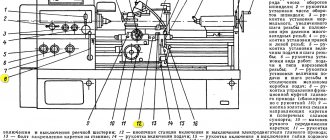
Adjusting spindle units . In Fig. 97 shows the spindle assembly of a screw-cutting lathe model 16K20. The front support of the spindle is a tapered double-row roller bearing 6 with a small cone angle at the inner ring and a shoulder on the outer ring. The rear end of the spindle rests on a tapered single-row roller bearing 2 with a small cone angle and automatic clearance elimination. Adjustment of spindle bearings should only be done if absolutely necessary, and be sure to first check the unit for rigidity. The check is carried out using a dynamometer and an indicator with a division value of 1 micron. The force from the dynamometer, directed vertically from bottom to top, is transmitted to the spindle through flange 7. The spindle movement is measured with an indicator mounted on the spindle head and its tip resting on the spindle flange. The bearing assembly is not subject to adjustment if the spindle shifts by 1 micron when a load of at least 45-50 kgf is applied. If this load is significantly lower, adjustment is necessary. Adjustment of the front bearing is carried out by grinding the half rings 8, to which the inner bearing ring is pressed using a nut 5 with a lock nut 4. The radial clearance in the bearing is eliminated due to deformations of the inner bearing ring when sliding it onto the conical journal of the spindle.
In order to remove the half rings, it is necessary to remove the parts covering the half rings from the front end of the spindle, unscrew nuts 4 and 5 and move the inner ring of the bearing. The gaps in the rear bearing are selected automatically using springs 9 resting on washer 3. Pre-compression of the springs is carried out by screwing nut 1 onto the threaded end of the spindle. The nut, through cup 10, displaces the inner ring of the bearing until it touches the shoulder, simultaneously compressing the springs. The adjustment of the bearing assembly is checked by reloading the spindle and measuring its displacement. If necessary, repeat the adjustment.
Rice. 97. Spindle assembly of screw-cutting lathe model 16K20
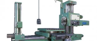
In Fig. 98 shows the spindle drive unit of the thread milling machine model 5B63G. The radial supports of the spindle 12 are sliding bearings 4 and 10. Axial loads are taken by thrust ball bearings 3 and 7. The sliding bearings have tapered internal surfaces with which they mate with the spindle journals. The gap in the mating pairs is eliminated by axial movement of the plain bearings.
The front bearing is moved by rotating two nuts 9 and 11, one of which is screwed in, and the other is released at this time. After adjusting the bearing, both nuts are tightened.
Rice. 98. Spindle drive unit for thread milling machine model 5B63G
The rear sliding bearing is also adjusted using two nuts 2 and 5. If it is necessary to reduce the bearing clearance in a mating pair, first release nut 2, and then unscrew nut 5 on the bearing to the required amount. After this, by rotating nut 2, the bearing is shifted to the right until nut 5 stops in housing 8. Using nut 2, the tightening force of the thrust ball bearings is simultaneously adjusted. After adjustment, both nuts are secured with locking screws 1 and 6.
The quality of regulation of spindle bearings is checked by the heating temperature of the bearings when the machine is operating at maximum spindle speed at idle speed. Rapid heating of the bearing indicates excessive tension during adjustment.
Spindle 16K20 16K20.020.401
Spindle assembly for screw-cutting lathe 16K20 16K20.020.401, as well as 16K20.020.398-01. You can also purchase spindle bearings 16K20.020.401, 16K20.020.398-01.
Spindle is the shaft of a metal-cutting machine that transmits rotation to the tool fixed in it or the workpiece being processed. The choice of spindle material is very important. Medium-load spindles are usually made from steel 45 with improvement (hardening and high tempering). For increased power loads, 45 steel with low tempering is used. For spindles requiring high surface hardness and a tough core, steel 45 with high-frequency hardening and low tempering is used. For increased requirements, steels 40Х, 38ХМУА (high-speed machine tool spindles), 20Х with carburization, hardening and tempering, 12ХНЗ (high-speed and heavily loaded spindles) and other low-alloy steels are used. Steel 65G is used for large spindles.
The structural shape of the spindles depends on the method of fastening the clamping devices or tools on it, the fit of the drive elements and the types of supports used. Spindles, as a rule, are made hollow for the passage of the rod, as well as to reduce weight. The front ends of the spindles of general purpose machine tools are standardized.
Supports. Rolling and sliding bearings are used as supports for machine tool spindles. Since spindles require high precision, the rolling bearings used in spindle supports must be of high accuracy classes. The choice of bearing accuracy class is determined by the runout tolerance of the front end of the spindle, which depends on the required processing accuracy. Usually, more precise bearings are used in the front support than in the rear one.
The design of spindle units is very diverse. In Fig. Figure 2.12 shows the spindle assembly of a screw-cutting lathe with a double-row roller bearing with a tapered hole in the inner ring as a front support. When the inner ring of the bearing moves axially, the conical neck of the spindle deforms the ring, and its diameter increases. This eliminates the radial gaps between the rollers and rings and creates a preload.
Preload is carried out in various ways. In angular contact ball bearings and tapered roller bearings, when installed in pairs, the preload is obtained by adjustment during assembly, and in radial ball bearings, by shifting the inner rings relative to the outer ones. In Fig. Figure 2.13 presents constructive methods for creating preload of ball bearings by grinding the ends of the inner rings (Fig. 2.13, a), installing spacers between the rings (Fig. 2.13, b), and using springs that ensure constant preload (Fig. 2.13, c). In Fig. 2.13, d shows a method for creating preload due to deformation of the inner ring when installing it on the conical neck of the spindle in roller bearings with cylindrical rollers. Sliding bearings used as spindle supports can be unregulated (they are rarely used, with almost complete absence of wear over a long service life), with radial, axial clearance adjustment, hydrostatic (they provide for the supply of oil under pressure into several pockets, from which it is forced out through the gap between the spindle journal and the bearing), hydrodynamic and gas-lubricated.
Precision machines use hydrostatic bearings, which create high precision spindle rotation. Their load-bearing capacity, rigidity and accuracy depend on the size of the gaps, pressure, and support pattern. In Fig. Figure 2.14 schematically shows the design of a hydrostatic support. Oil under pressure is supplied to pockets 1 through holes 2. During rotation, oil is forced out of these pockets through the gap between the journal and the bearing and from hole 3 into the reservoir. As the external force increases, tending to reduce the gap, the oil pressure in the reservoir increases and the gap is restored. Hydrostatic bearings stabilize the friction mode with the lubricant at the lowest rotation speeds.
A self-aligning hydrodynamic plain bearing used in grinding machines is shown in Fig. 2.15. In the holder 4 there are five self-aligning liners 5. Each liner has one spherical support in the form of a pin 3. The pins are secured in the holder with screws 2 and 8 with washers 1 passing through the cover 7. O-rings 6 are provided between the cover and the holder.
The inserts are self-aligned by spherical supports in the direction of rotation of the spindle and in the direction of its axis. This creates reliable friction conditions with the lubricant in the support and stable oil wedges, and also avoids edge pressures caused by misalignment of the working surfaces, elastic or thermal deformations of the spindle. The design of the bearings ensures high precision of spindle rotation due to its centering by hydrodynamic pressures that arise in several zones around the circumference.
Spindle bearings must be reliably protected from contamination and lubricant leakage. Lip seals (Fig. 2.16, a) made of leather, plastic or oil-resistant rubber are placed in a metal casing and pressed against the shaft with a bracelet spring. In machine spindles, it is more advisable to use labyrinth seals (Fig. 2.16, b), which do not have rubbing surfaces and can operate at high rotation speeds. They provide bearing protection by resisting fluid flow through narrow slots. In Fig. 2.16, c shows seals for vertical shafts, seals with piston-type rings and a combined felt seal with a baffle ring that rejects oil.