In this article we will look at various connection diagrams for soft starters using the Prostar PRS2 soft starter as an example.
Soft starters are produced by many manufacturers, and they all have their own characteristics. However, there are general connection principles that are valid for any soft starter model.
All conductors connected to the starter can be divided into power and control. Power circuits are responsible for supplying power. Control circuits are on/off circuits (switching), signaling, etc. They provide not only starting and stopping the engine, but also protecting the soft starter in case of emergency situations.
The general connection diagram for the Prostar PRS2 soft starter is as follows:
Disadvantages of power tools and service life
It is well known that not every tool is equipped with such soft start circuits. They mainly come in expensive models from well-known brands Bosch, Hilti, and DeWalt. Moreover, both in the network line and in the battery one.
A power tool without such a device has a bunch of disadvantages:
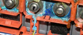
- armature sparking on the commutator with armature lamellas burning out
- brushes burn out and wear out faster
- rotor and stator windings fail more often
- current surge into the general electrical network
- gears hitting each other and operating faster
- dangerous jerk when starting, tearing the tool out of your hands and increasing the risk of injury
When working with a miter saw with a PP, the blade will not stray from the prepared cutting point. Which is important for non-professional carpenters.
If at your dacha or in your house at the initial stage of construction there is no electricity yet and you use a generator, then sooner or later you will understand that without a soft start unit (soft start unit) with sharp initial currents, the generator will not last long. Therefore, such a thing can save not only the tool, but also emergency power supplies.
You can, of course, independently build a BPP into the inside of the same grinder or trimmer, but not everyone wants to disassemble the equipment and tinker with the insides.
Plus, opening a new case will void the warranty. Therefore, the best use for the KRRQD12A unit is external connection.
Just keep in mind that it is suitable for commutator motors. For asynchronous ones, a frequency generator with different regulation principles is needed.
This box is designed for a current of 12 Amps.
There is also a more powerful 20A model.
What is typical is that they have the same dimensions, but the difference in price is a couple of tens of rubles.
It would seem better to take it, but for a standard 16A socket the first option is more profitable. There will be no desire to connect a more powerful load and thereby burn all the contacts.
DIY craftsmen, of course, assemble similar circuits with their own hands, based on VTA 12-600 or other thyristors, capacitors, a dinistor and a couple of small resistors. You can find many examples of schemes on the Internet.
But for the average user of the instrument, it is much easier to buy all this in a ready-made compact case. You can order a similar block using the link here.
Direct launch
In a direct start electrical circuit, the machine is directly connected to the mains supply voltage.
The diagram above shows the inrush current characteristic for direct starting. With this connection, the temperature increase in the windings of the machine is minimal.
The connection is made using a contactor (starter). The circuit uses an overload relay to protect the electric motor. However, this method is applicable when there are no current restrictions.
During the start of the machine, the starting torque is limited in order to smooth out a sharp jerk, as a result of which the mechanical parts of the drive and connected mechanisms may fail.
For this reason, manufacturers of large electric motors prohibit direct starting.
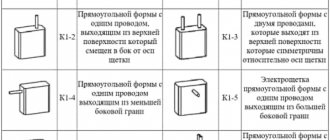
Soft starters with three wires
By the way, be careful, there are similar devices, but with three wires. For example XS-12/D3.
Or other models that look similar to KRRQD.
But they are assembled on a slightly different principle and need to be installed after the START button, in the instrument itself. Voltage should be applied to them only at the moment the grinder's start button is closed and immediately disappear after it is released.
The connection diagram for them is as follows:
The phase is supplied to contact “A”, zero to “C”. Next, the phase with the output control wire goes to the engine (this is exactly the third wire).
Without a button, such a device will be constantly powered by 220V, which is not acceptable.
There is no such thing in a two-wire unit, since it is connected to an open circuit, and voltage (potential difference) is applied to it only at the moment of starting and operating the tool.
Another point is the so-called electric brake or brake winding on the crosscuts. It may not work with a 3-wire external soft starter, but it will work with a 2-wire model.
How to assemble a regulator circuit with your own hands
The simplest power regulator, suitable for an angle grinder, soldering iron or light bulb, is easy to assemble with your own hands.
Electrical circuit diagram
In order to assemble a simple speed controller for an angle grinder, you need to purchase the parts shown in this diagram.
Schematic diagram of the speed controller
- R1 - resistor, resistance 4.7 kOhm;
- VR1 - trimming resistor, 500 kOhm;
- C1 - capacitor 0.1 µF x 400 V;
- DIAC - triac (symmetrical thyristor) DB3;
- TRIAC - triac BT-136/138.
Circuit operation
Trimmer resistor VR1 changes the charging time of capacitor C1. When voltage is applied to the circuit, at the first moment of time (the first half-cycle of the input sinusoid), triacs DB3 and TRIAC are closed. The output voltage is zero. Capacitor C1 charges and the voltage across it increases. At a certain point in time, specified by the R1-VR1 chain, the voltage on the capacitor exceeds the opening threshold of the triac DB3, the triac opens. The voltage from the capacitor is transmitted to the control electrode of the TRIAC triac, which also opens. Current begins to flow through the open triac. At the beginning of the second half-cycle of the sinusoid, the triacs are closed until capacitor C1 is recharged in the opposite direction. Thus, the output produces a pulse signal of complex shape, the amplitude of which depends on the operating time of the C1-VR1-R1 circuit.
Assembly order
Assembling this circuit will not be difficult even for a novice radio amateur. Spare parts are available and can be purchased at any store. Including desoldering from old boards. The procedure for assembling the regulator using thyristors is as follows:
Manufacturing a soft start socket
The most important requirement for such an outlet is its mobility. Therefore, you will need a carrier.
With its help, you can smoothly launch the tool anywhere - in the garage, at the dacha, during the construction of your house in different areas of the construction site.
The first step is to disassemble the carrier.
The main power wires in it can be either soldered or connected to screw terminals.
Depending on this, your additional outlet will also be connected. This should be an additional socket near the carrying case in order to be able to simultaneously connect the instrument in different modes.
By the way, if you mistakenly turn on an angle grinder or circular saw that has a factory built-in soft start into an outlet that is also equipped with such a soft starter, then surprisingly everything will work. The only thing is that there will be a delay in starting the saw or turning the disk for a couple of seconds, which is not very convenient to use and can be puzzling if you don’t get used to it.
Here are real tests of such a connection, carried out by one master from YouTube BaRmAgLoT777. His comment after such tests on a Dremel type engraver, a Bosch drill, a Makita router, and an Interskol circular saw:
Next, to assemble the socket, take a stranded copper wire with a cross-section of 2.5 mm2 and strip its ends.
Then you need to tin the contact pad on the carrier where this wire will be soldered.
Securely solder the cable cores to these pads.
Carefully lay out the wires and close the extension cord.
Take a square external socket for installation on the outer surface of the walls, and try on a soft starter unit in its housing. Since it has compact rectangular dimensions, it should fit there without any problems.
Mount and secure the socket body on the same platform as the extension cord.
The PP block is connected to the gap of any wire, phase or neutral. Do not confuse it, phase and zero are not supplied to it at the same time, i.e. 220V.
It is installed on one of the wires.
Also for this BPP, there is no difference on which side to make the entrance and on which side to make the exit. The twists are soldered and insulated with heat shrink.
After that, all the insides of the socket are assembled into a housing and all that remains is to close the entire structure with a lid.
At this point, the entire reworking of the carrying case and the manufacture of the socket can be considered complete. It will take you no more than 15 minutes.
How to connect a regulator to an angle grinder
To connect a homemade power regulator, no special knowledge is required, and any home craftsman can cope with this task. The module is installed in the gap of one wire, through which power goes to the angle grinder. That is, one wire remains intact, and a regulator is soldered into the gap of the second.
If there is very little space in the grinder, then the regulator can be placed outside the tool, as shown in the following photo.
Also, the regulator can be placed in a socket and used to reduce the speed not only of an angle grinder, but also of other electrical appliances (drill, sharpener, wood milling or lathe, etc.). This is done as follows.
- Purchase a junction box from an electrical goods store (suitable with dimensions 65x65x50 mm).
- You should also buy a small outdoor socket and a power cable with an electrical plug.
- Drill a hole in the side wall of the junction box to insert a variable resistor regulator into it.
- The factory regulator board or a homemade device is placed inside the junction box. All protruding parts in the box that interfere with installation can be cut off.
- The socket should be secured to the cover of the distribution box, having first pulled the wires inside the latter.
- In the figure above you can see that the wires of the network cable touch the radiator, which heats up during operation. That's why it's wearing a PVC tube. But it’s better if you drill a hole for the network cable in a different place to prevent it from coming into contact with the radiator.
The following photos show what a finished socket will look like, having a built-in speed controller for an angle grinder, which can also be used for other electrical appliances.
Instead of a junction box, you can use any plastic case of a suitable size. You can also make the box yourself by gluing pieces of plastic together with a glue gun.
Differences between scalar and vector frequency converters
A scalar quantity is a value expressed as a single number. Several values are shown on the scale. Area and length are scalar quantities. Vector quantities - in addition to numbers, have a direction.
The main method of changing the motor torque is to adjust the frequency and current. This leads to a change in the field strength. Frequency drivers can be configured and their output parameters changed for your mechanisms. The nature of the output current of the output of the frequency converter can be given a hyperbolic, parabolic, linear form.
To move a heavy load on the mechanism, the output current is given a hyperbolic appearance. Fans and water pumps are driven in a parabolic manner, this saves electricity. This is how many frequency converters, called scalar ones, are designed.
The next method of increasing motor torque is to use harmonics of the output current. Its vector rotates towards the main harmonic current, according to a direct sequence. The rest create a reverse rotation in a reverse sequence.
The neutral current is higher than the phase currents, the oscillations of the 3rd harmonic are greater than the following harmonics. This effect is used to increase the power output and increase the torque on the motor. To control torque, current strength and frequency, as well as phase, are used. This is where the name “vector” comes from.
Optimized rotational consistency over a wide range by phase shifting. This property is contained in a closed rotor motor. The field passes through the rotor, where there are currents that create mechanical force. It rotates the motor shaft towards the stator field, but the rotor lags several percent behind the rotation speed of the flow field. This sliding ensures the conversion of electrical energy into mechanical energy in an asynchronous motor. If there is no slip in the rotor, there is no driving force and there is no rotation of the motor shaft.
The torque of the motor is directly proportional to the current, and inversely proportional to the engine speed. The effect of vector methods is small. At low speeds with increased current, the electric motor overheats and requires a cooling system. Do “non-vector” frequency converters have a constant motor rotation torque? An asynchronous motor has the property of changing the torque according to the shaft load, that is, it consumes a current that provides the same torque and load.
At the lowest speeds of rotation of the engine shaft, vector control methods are ineffective. The cost for the “vectoring” property of a frequency converter is not justified; the complexity of the system reduces the reliability of the mechanisms. Such frequency converters cannot be used on drives with multiple motors. Frequency converters should be classified according to the method of controlling the output current:
- With adjustable current values. Used in general purpose drives.
- With dynamic type output current setting. They are used in drives with one motor on precision process units. There are fields with and without field feedback. They are superior to the first type of frequency converters, but servos are superior to them.
For specific purposes, electric motors with their own control systems are used to control mechanisms. It is impossible to create universal mechanisms and drives, since there is a big difference in the design and in the tasks performed. It is necessary to design the mechanism drive, take into account the required motor torque in the negative range of rotation speeds, and the parameter value will be controlled by a regulator; scalar-type converters are equipped with it.
What is it for?
If the tool is not equipped with a speed controller, then it does not need one. An angle grinder, for example, is always used at full speed, otherwise it becomes dangerous. Why does such a power tool need a soft start? There are many reasons, because a sharp start of the engine of the same grinder or electric jointer causes:
- burnout of brushes and rotor lamellas;
- electric shock in the electrical network;
- an attempt of the instrument to escape from the hands, which is unsafe;
- strong starting impact of the gears of the gearbox against each other, causing their rapid wear.
With a smooth start, neither current nor mechanical shock will occur. The power tool engine will start smoothly and reach maximum speed.
Homemade options
There are many schemes for modernizing power tools using soft starters. Among all varieties, devices based on triacs are widely used. A triac is a semiconductor element that allows you to smoothly regulate power parameters. There are simple and complex circuits that differ in design options, as well as in the supported power of the connected power tool. The design includes internal ones, which allow them to be built inside the case, and external ones, manufactured in the form of a separate module, which acts as a speed limiter and starting current when starting the angle grinder directly.
The simplest scheme
A soft starter with speed control on a thyristor KU 202 is widely used due to its very simple design (diagram 1). Connecting it does not require any special skills. Radio elements for it are very easy to obtain. This regulator model consists of a diode bridge, a variable resistor (acts as a U regulator) and a thyristor tuning circuit (supplying U to the control output with a nominal value of 6.3 volts) from a domestic manufacturer.
Due to the size and number of parts, this type of regulator can be built into the body of a power tool. In addition, the variable resistor knob should be removed and the speed controller itself can be modified by integrating a button in front of the diode bridge.
The basic principle of operation is to regulate the speed of the electric motor of the tool by limiting the power in manual mode. This circuit allows you to use power tools with a power of up to 1.5 kW. To increase this indicator, it is necessary to replace the thyristor with a more powerful one (information about this can be found on the Internet or in a reference book). In addition, you need to take into account the fact that the thyristor control circuit will differ from the original one. KU 202 is an excellent thyristor, but its significant drawback is its configuration (selection of parts for the control circuit). To implement a soft start in automatic mode, scheme 2 is used (soft starter on a microcircuit).
Soft start on a chip
The best option for manufacturing a soft starter is a soft starter circuit with one triac and a microcircuit that controls the smooth opening of a pn type transition. The device is powered from a 220 V network and is easy to assemble yourself. A very simple and universal soft start circuit for an electric motor also allows you to regulate the speed (diagram 2). The triac can be replaced with the same one or with characteristics exceeding the original ones, according to the reference book of semiconductor-type radioelements.
Scheme 2. Scheme for soft start of a power tool
The device is implemented on the basis of the KR118PM1 microcircuit and a triac. Due to the versatility of the device, it can be used for any tool. It does not require configuration and is installed into the power cable.
When the electric motor starts, U is supplied to KR118PM1 and the charge of capacitor C2 gradually increases. The thyristor opens gradually with a delay depending on the capacitance of the control capacitor C2. With a capacitance of C2 = 47 μF, there is a delay at startup of about 2 seconds. It depends directly proportionally to the capacitance of the capacitor (with a larger capacitance, the startup time increases). When the angle grinder is turned off, capacitor C2 is discharged using resistor R2, the resistance of which is 68 k, and the discharge time is about 4 seconds.
To regulate the speed, you need to replace R1 with a variable resistor. When changing the parameter of the variable resistor, the power of the electric motor changes. R2 changes the amount of current flowing through the triac input. The triac needs cooling and, therefore, a fan can be built into the module housing.
Thus, to start electric motors of various tools, it is necessary to use factory-made or home-made soft starters. Soft starters are used to increase the service life of the tool. When starting the engine, there is a sharp increase in current consumption by 7 times. Because of this, the stator windings may burn out and the mechanical part may wear out. Soft starters can significantly reduce the starting current. When making a soft starter yourself, you need to follow safety rules when working with electricity.
A soft starter is an electrical device used in asynchronous electric motors, which allows the motor parameters (current, voltage, etc.) to be kept within safe limits during startup. Its use reduces starting currents, reduces the likelihood of motor overheating, eliminates jerks in mechanical drives, which ultimately increases the service life of the electric motor.
Double-sided cut
Quite often, when attaching a sheet to a profile in difficult places, it is necessary to perform a double-sided cut. This method is used when designing window openings, door openings, and, if necessary, bypassing beams and other complex structures. What is the best way to cut drywall in this case? First you need to make a hole of a rectangular or square shape. You can cut it using such a simple tool as a hacksaw or a sharp knife. The cutting process is not difficult:
- First you need to mark the sheet with a simple pencil and ruler;
- on one side the sheet must be cut using a hacksaw, and on the other using a knife;
- Now the drywall is cracking and being cut off on one side.
Afterwards, you need to carefully process the edge using a roughing plane to get smooth edges. When the sheet is cut, you can fix it in the required place using self-tapping screws. After installation, joints and seams are puttied and pre-glued with a special mesh.
Why is the starting current of an electric motor dangerous?
When voltage is applied to the stator winding, the rotor rotation speed is zero. The rotor must be moved and spun to the rated speed. This requires significantly more energy than what is needed for the nominal operating mode.
Under load, inrush currents are higher than at idle. The mechanical resistance to rotation from the mechanism driven by the engine is added to the weight of the rotor. In practice, they try to minimize the influence of this factor. For example, for powerful fans, the dampers in the air ducts automatically close at the time of startup.
At the moment the starting current flows from the network, significant power is consumed to bring the electric motor to its nominal operating mode. The more powerful the electric motor, the more power it needs to accelerate. Not all electrical networks tolerate this regime without consequences.
Overloading the supply lines inevitably leads to a decrease in network voltage. This not only makes starting the electric motors even more difficult, but also affects other consumers.
And the electric motors themselves experience increased mechanical and electrical loads during startup processes. Mechanical ones are associated with an increase in torque on the shaft. Electrical ones, associated with a short-term increase in current, affect the insulation of the stator and rotor windings, contact connections and starting equipment.
Frequency regulation
Frequency regulation refers to the use of a frequency-controlled drive. This device regulates the rotor speed of the electric motor. The design of the frequency converter includes an inverter and a rectifier. The advantages of starting an engine through frequency regulation include a large selection of values for adjusting the number of revolutions, an increase in the service life of the motor, maximum starting torque and saving electrical energy compared to other methods of starting the motor.
Frequency regulation also has disadvantages. This is the relatively high price of converters for powerful motors, as well as the high level of interference that is observed in the vicinity of these devices.
Data collected when visiting the site
Personal Information
This data is collected for the purposes of providing services or selling goods, communicating with the user or other user activity on the site, and to send users information that they have agreed to receive.
We do not check the accuracy of the data provided, but we do not guarantee high-quality execution of orders or feedback from us if the data is incorrect.
The data is collected using forms available on the site for filling out (for example, registration, placing an order, subscribing, leaving a review, feedback, and others).
Forms installed on the site can transmit data both directly to the site and to third-party sites (scripts for third-party services).
Data may also be collected through cookie technology, both directly by the site and by scripts from third-party services. This data is collected automatically; the sending of this data can be prevented by disabling cookies in the browser in which the site is opened.
Non-personal data
In addition to personal data, when visiting the site, non-personal data is collected; it is collected automatically by the web server on which the site is located, CMS (content management system) tools, and third-party scripts installed on the site. Data collected automatically includes: IP address and country of registration, the name of the domain from which you came to us, visitors’ transitions from one page of the site to another, information that your browser provides voluntarily when visiting the site, cookies, visits and other data collected by third-party analytics counters installed on the site are recorded.
This data is non-personal in nature and is aimed at improving customer service, improving the usability of the site, and analyzing traffic.
Preparing to install the device
Making and using a carrier with a small power supply will save money on the purchase of new power tools, extending the service life of old ones. For domestic conditions, it is enough to use a 12A unit with the abbreviation KRRQD12A (see figure below).
Such a device should be used for starting and operating commutator types of power tool motors with a power of up to 2500 Watts. Having purchased a BPP, you should select an extension cord of sufficient length for operation. You also need to prepare a separate socket, a piece of stranded soft copper wire, tools, heat shrink or electrical tape. If the wires in the extension cord are soldered and not bolted, you will need a soldering iron, rosin, and solder.