Centrifugal clutch The work is based on the transmission of torque through petals that provide traction from the action of centrifugal forces. Malfunctions of the angle grinder associated with wear or destruction of the sliding bearing on the gearbox shaft are characterized by the appearance of an unpleasant extraneous sound. Electrical diagram of the grinder. Internal structure of the grinder. You can also use tweezers with cotton wool or rags soaked in cologne. The drill is turned on and a small number of revolutions is set. Why do you need a capacitor in a power tool?
If uneven wear of shaky shafts or teeth is detected, then it is necessary to replace the worn parts as quickly as possible.
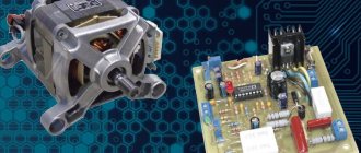
Checking the start and control unit Next, you should test the start button and the electronic control unit. Before you start repairing an angle grinder with your own hands, it is best to have in front of you a layout and electrical diagram and detailed instructions that correspond to a specific model.
But this cannot be done. Repair of an angle grinder rotor Failure of the rotor in an angle grinder is caused by improper use of the tool, frequent overheating, untimely replacement of carbon brushes, and abrasive particles and dust getting on the collector slats.
Diagnosis of malfunctions in the operation of angle grinders Signs of improper operation of an angle grinder for a sensitive ear and a keen eye appear long before the actual failure of the tool. But due to significant design upgrades, it quickly began to perform such useful functions as cutting and processing any building materials, including cement, concrete, brick, tiles, slate and all types of metals.
Diagnosis of grinder malfunctions
About the tool
The history of the origin of this unique device for cutting metal began back in Soviet times. 50 years ago it was the dream of every citizen of our country to have an angle grinder at home. The name comes from the manufacturer’s plant, which was the developer and manufacturer of the device - “Eltos-Bulgarka”. The instrument was made in Bulgaria, which is why the name gradually became attached to it. Despite significant improvements in this technology, today the same structural elements remain at the heart of the grinder.
Stators
408-317 Stator for BOSCH GWS7-125/GWS7-115 HAMMER. Photo 220Volt
The compact design of an electric drive and a mechanical gearbox, which increases the torque on the working shaft, allows the angle grinder to be successfully used as a hand-held power tool in terms of weight and overall dimensions. The ease of replacing attachments on the working spindle makes the grinder a convenient universal device for processing a wide variety of materials (metal, wood, plastic, stone and many others). The grinder is popular both among users who perform simple work at home, and among professionals who perform complex work that requires high qualifications. The main structural element of the electric drive of an angle grinder is the stator. This article describes the features of this one of the main components of the electrical part of the angle grinder.
Electrical part of the grinder
There have been no significant changes in the design of the instrument recently. The body is oblong, inside there is a gearbox with a motor, a handle on the side and a protective casing on top of the abrasive wheel.
The tool does not always work smoothly, and there are circumstances when it becomes necessary to simply disassemble it and lubricate some elements with oil as a preventative measure. To do this, you need to know the design and be able to use drawings, including the electrical circuit of the angle grinder. The ability to correctly read technical documents and understand how equipment works will help perform any type of repair work.
The electrical circuit of the grinder contains the following elements that ensure its movement:
- collector;
- gearbox;
- handle holders;
- anchor;
- electric brushes;
- stator;
- cable for power supply.
Each of these elements has its own purpose; if any of them breaks, the tool will not work.
Troubleshooting
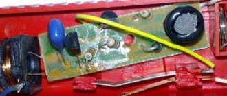
Quite often, a breakdown of a radio element can be detected as a result of a visual inspection, by characteristic swelling, darkening, cracks or other violations of the integrity of the housing. As an example, the photograph shows such signs.
Breakdown of ceramic and electrolytic capacitors
Unfortunately, it is not always possible to visually detect a non-working radio element; a completely normal-looking part, the whole body of which does not have pronounced defects, may be inoperative due to an internal short circuit.
Before you start checking a non-polar film, ceramic, electrolytic, smd or sbb capacitor with a multimeter, you should remove it from the board, since it is practically impossible to test without soldering the radio component.
To be fair, it should be noted that there are several ways not to resort to a soldering iron, one of them is to measure the circuit resistance on the board, but this will require a resistance map, moreover, for the specific model of the broken device, and this is not always available even in official service centers.
The purpose of each power supply element of the angle grinder 125
The grinder circuit includes several elements that ensure its smooth operation.
Purpose of elements for power supply:
- Anchor. This part facilitates the movement of the abrasive wheel for cutting metal products and workpieces. It is necessary to create greater speed in relation to the disks to ensure their rotational movements. And, accordingly, at a higher anchor speed, the power indicators of the tool are higher.
- Collector. This is a platform located on an anchor to which all power lines are connected. Its main function is to transmit signals through the windings to the motor and control unit so that the elements correctly perceive this information. The element immediately catches your eye when you remove the cover from the case, as it has a polished surface and its dimensions are quite large.
- Electric brushes. The purpose of these elements is to supply electric current to the cable. During normal operating placement, a glow will be observed emanating from them through the opening provided for ventilation. If it is noted that this is absent, is weak or almost unnoticeable, then this is an indicator that there is a problem with the electric brushes.
- Gearbox. The main structural part for the electrical circuit and for the entire technical device as a whole. Its function is to transfer electricity from the armature to the abrasive disc. This ensures rotation, which creates work. In fact, only the gearbox helps to increase the speed and power characteristics of angle grinders.
- Stator. This is the most complex knot that complements the grinder device. It is in it that the windings of both the armature and the rotor are located, which are the primary mechanisms that provide movement. The windings of the stator coil are clearly calculated until the last turn. If this element fails, it is unlikely that an inexperienced worker will be able to restore the winding. This happens, but in exceptional cases. It is best to contact a specialized workshop regarding stator rewinding.
Read also: How drying is done in production video
How to connect a regulator to an angle grinder to reduce or increase speed
Every craftsman has a good grinder It is popular among professionals and in any household due to its convenient operation and multitasking. The tool is designed as a grinder, but its unique bevel gear has made it the most popular saw. When installing the appropriate discs, the angle grinder saws and cuts various materials, grinds and polishes surfaces, easily penetrating hard-to-reach places.
Since materials for cutting and grinding come across different hardness and texture, the speed of rotation of the disk when cutting them should be different. Otherwise, the cutting wheel will not perform its task or, moreover, will jam in the material at the most inopportune moment and lead to engine failure.
The ideal option is a model in which the manufacturer has a built-in speed controller. Buying an angle grinder with speed control is the best solution.
Making a speed controller for an angle grinder with your own hands
The simplest regulator can be assembled with your own hands. Those home craftsmen who understand electrical circuits can easily make a speed controller using a simple semiconductor circuit.
There are several ways to make a regulator and integrate this block into an instrument; it can be installed inside the body or attached externally as a separate element. In any installation, he will be able to regulate the speed.
The external board can also be mounted in a separate plastic box, equipped with a plug and socket. In fact, this is the same transfer of starting current; the angle grinder is turned on through it, and the speed is adjusted with the wheel on the box. This makes an excellent polishing machine.
This method is more complicated, but it makes it possible to fit into a case, which is compact and convenient.
- Before installing the circuit, you need to replace the keys that connect the instrument to the network.
- Space will be freed up. Here you need to put electronic keys - a triac or thyristor to switch rotation speeds.
- You can also connect a soft start chip, which will make it possible to avoid a jerk at the start.
What tasks require adjustment?
Grinders with a speed controller are used:
- When grinding and cutting very thin sheets (metal or plastic). In this case, you need to reduce the speed to almost zero speed. The torque must be calculated so that the material does not melt.
- For cutting tiles, ceramics, artificial or natural stone. At the beginning of the cut, you need to increase the rotation speed, then reduce it, and at the end increase the speed again so that chips and cracks do not appear.
- When working with diamond-coated discs. It is better to cut with them at low speeds, this way there is no strong heating and you can work longer.
- When working with polishing attachments, especially when finishing polishing.
READ How to Remove Grinder Marks on Glass
Pros and cons of a DIY regulator
The upside is that your angle grinder will get additional features. You can change the speed of rotation of the disk, lower and increase the speed.
But home technology also has several disadvantages:
- It gets very hot, so you can’t put a load on it for a long time. We recommend an operating mode with periodic shutdowns to allow the machine to cool down.
- Loss of power. Semiconductor regulators adjust the current well and perfectly change the spindle speed. But at the same time, unfortunately, the power of the tool decreases. Only the factory installed power regulator keeps the engine at 100% power.
It is worth noting that the drop in power is only relevant when working with stone and ceramic tiles. And when cutting thin-sheet materials, where it is very important to reduce the speed, the loss of power is almost unnoticeable.
How to read a wiring diagram
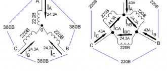
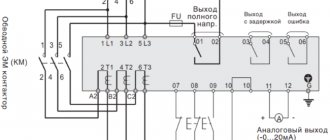
In order to properly repair or carry out maintenance on an angle grinder, you must first of all learn to read the circuit diagrams of power tools, including the electrical circuit. In general, it does not seem so complicated, but sometimes it is difficult for a simple worker to understand it, so he has to turn to professionals. The connection diagram of the technical device reads as follows:
- 2 stator windings are connected in series through a power cable with a standard voltage of 220 V, and they are not interconnected. They are turned on and off using a switch, the operation of which is ensured by pressing the start button. Each winding is protected through a graphite brush contact;
- two brushes connected in parallel to the graphite windings are closed on the commutator. Despite the fact that the armature winding consists of several, only two are connected to graphite brushes. The grinder device fails in 9 cases out of 10 when the electrical circuit opens.
To correctly assess the operation of a power tool, a specialized device is used - an electronic multimeter. This is a unique tester that can be used not only to determine a malfunction in an angle grinder, but also in other power tools. First, a fault is diagnosed at the current input, then a sequential ringing of the entire technical device is performed. To check conductivity, you need to set the minimum resistance level.
What is the winding resistance
Multimeter Zubr. Photo 220Volt
Winding damage is diagnosed using resistance measuring instruments . Here ohmmeters or multimeters in the mode of determining circuit resistance.
Important : for high-quality measurements, it is necessary to correctly select the instrument scale, within which the resistance of the winding being diagnosed is located.
The windings of grinders, made of copper wire, have a resistance value depending on the power: low power - closer to 2 Ohms , higher power - about 6 Ohms . If the winding resistance is greater than the specified values, then we can conclude that the performance of the coils has decreased and their possible early failure. If there are no indications on the device, we can conclude that there is a break in the winding.
How to make repairs
If the angle grinder does not start when the start button is turned on, then there is reason to believe that the reason here is not so serious, and it is not difficult to carry out repair work yourself. Just a few recommendations for carrying out repair work to start with simple ones and end with more complex ones.
- If the electrical circuit of the angle grinder 1100 E device breaks, remove the protective casing and check with a tester for the presence of voltage in the trigger mechanism. If there is no starting current, then the problem is a faulty electrical wire. In this case, it is necessary to replace the wire with a new one. This will allow the simplest repairs to be made to the 1100 E device.
- If there is current when you turn on the “start” button, and then no current flows into the device, then the problem itself lies in the button, so you should replace it with a new one. There is no need to rush in this matter; first, you should disassemble the mechanism, marking the parts one by one to avoid mistakes during assembly. To replace a rejected element, you can select another one that matches the parameters. Particular attention must be paid to the contacts: if they are connected incorrectly, the winding may have burned out or the armature has jammed.
- If, when the wire and start button are in full working order, no current flows to the brushes, then the brush holder plates should be cleaned. If the 1100E mechanism does not continue to work, then it is necessary to replace the old brushes with new ones.
You can read about how to connect a technical device, including an angle machine, in the operating instructions or on the Internet.
Making a speed controller with your own hands
Trying to adapt a regular dimmer to adjust the brightness of the lamp will not yield anything. Firstly, these devices are designed for a completely different load. Secondly, the operating principle of the dimmer is not compatible with controlling the electric motor winding. Therefore, you have to mount a separate circuit and figure out how to place it in the tool body.
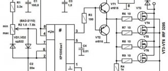
The simplest thyristor rotation speed controller can easily be made independently. To do this, you will need five radio elements, which are sold on any radio market.
Electrical circuit of a thyristor speed controller for your instrument
The compact design allows the circuit to be placed in the body of an angle grinder without compromising ergonomics and reliability. However, this scheme does not allow maintaining torque when the speed drops. This option is suitable for reducing speed when cutting thin sheet metal, carrying out polishing work, and processing soft metals.
If your grinder is used for stone processing, or discs larger than 180 mm in size can be installed on it, you need to assemble a more complex circuit, where the KR1182PM1 microcircuit, or its foreign equivalent, is used as a control module.
Electrical circuit for speed control using the KR1182PM1 microcircuit
This circuit controls the current strength at any speed, and allows you to minimize the loss of torque when they decrease. In addition, this scheme is more gentle on the engine, extending its life.
The question of how to adjust the speed of the tool arises when it is stationary. For example, when using a grinder as a circular saw. In this case, the connection point (machine or socket) is equipped with a regulator, and the speed is adjusted remotely.
Regardless of the method of execution, controller expands the capabilities of the tool and adds comfort when using it.
Why control the speed of the disk?
Different cutting or grinding speeds are required according to the physical properties of the materials being worked with. Thus, high speed with low pressure is required when cutting hard materials that might otherwise crumble or splinter. Soft materials that are not resistant to heat (thermoplastics, wood), on the contrary, require low speed:
- ceramics: 10000 rpm;
- metal: 8000 rpm;
- hard plastics: 5000 – 8000 rpm;
- wood: 3000 – 5000 rpm;
- soft plastics: less than 2000 rpm.
A small but very important detail! Why did the speed controller stop working on the Makita 9562?
All professional tools are equipped with a stabilized speed controller, but inexpensive household angle grinders with a power of less than 1200 W are not always supplemented with it. In this article we will talk about how to make such a regulator yourself to reduce the speed.
How to replace graphite brushes
Based on practical data, it has been established that the most vulnerable part in a technical device, including the 1100E, is graphite brushes. Their service life is no more than 2 years. To replace old brushes with new ones, you do not need to have experience. Such manipulation will not be difficult even for an inexperienced person. To examine the condition of the brushes, you need to open the tool body, including the 1100E.
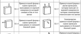
In this case, the device must be de-energized, and the brush holders installed on the commutator must be carefully moved to the side. The use of a screwdriver for this operation is mandatory.
If the technical device is manufactured by a specialized company, then the brushes can be held in place using a spring. To remove the brush, you need to press these springs with a screwdriver. If the manufacturer of the tool is China, then in these places there are plugs, which are also removed with a screwdriver, and only after that the brush can be easily removed. To determine which brush you need to purchase, it is recommended to take the removed part with you to the store and, accordingly, select a similar one there, strictly according to the given parameters. When inserting a brush into an angle grinder, these actions must be performed smoothly and slowly. It is important to note that it does not cling to anything and is installed evenly in the socket.
Read also: Drill attachments for wood milling cutter
In the same way as the installation of the first brush, you can install the second one. After this, you need to check the location of the wires in the technical device so that they are not pinched anywhere. Now you can close the case and turn on the machine in test mode.
Any power tool with a commutator motor (grinder drills and others) has a rather large capacitor (0.2 - 0.5 mF). Even a cheap Chinese instrument contains this element. Searching for an answer on the Internet yielded nothing except that it was needed “to reduce the interference created by sparking brushes.” I think its role is to dampen the sparking of the brushes, reducing the heating of the commutator and brush assembly. And a decrease in sparking leads to a decrease in interference. Who knows the exact answer?
This capacitor is from a Chinese grinder with a power of 600 Watt.
The capacitor is installed in devices with a commutator motor precisely to dampen high-frequency interference that occurs during engine operation. The resistance of a capacitor is inversely proportional to the frequency of the alternating current flowing through it. For alternating current with a frequency of 50 Hz, the resistance of a capacitor with a small capacitance is so high that the current flowing through it can be neglected.
Another thing is high-frequency interference from collector sparking. For them, the capacitor resistance is low. And the current with the interference frequency mainly flows through the capacitor without entering the power supply.
In more expensive devices, an inductance is also placed in the power supply circuit break, the resistance of which for RF current is high. Together, the capacitor and inductance(s) make up a classic high-pass filter.
After a certain period of use, the grinder is characterized by such breakdowns as wear of the graphite brushes, burnout of the stator windings, and so on. Of course, wear itself also occurs in terms of mechanics. To fully familiarize yourself with the topic: “How to repair an angle grinder,” let’s look at the electrical circuit of a commutator AC motor, since just such an electric motor is installed in an angle grinder.
Technical indicators
- The power consumed by the power tool is 1100 W.
- Voltage - 220 V/50 Hz. Power comes from the electrical network.
- Speed: from 3000 to 10,000 per minute.
- Weight is 2.2 kg.
- The power tool is designed for a circle with a diameter of 125 mm.
- The main handle is three-position.
- Smooth start.
- There is a function for adjusting the rotation speed.
- There is a fixed spindle.
When selling Interskol, the UShM-125/1100E is equipped with:
- additional handle;
- a set of gaskets;
- a special key for installing discs and attachments.
AC brushed motor circuit diagram
The diagram (Fig. 1) shows the electrical connections of the stator windings, rotor and graphite brushes. Graphite brushes in the electric motor are installed in brush holders. The brushes are in contact with the commutator lamellas. Some ends of the stator windings are connected to an external energy source. The other ends of the stator windings are connected to graphite brushes, the electrical circuit is closed on the rotor windings.
The angle grinder's speed controller is connected by wires to the commutator motor circuit in series. The connection diagram for the speed controller should be indicated on the regulator body itself, or in the grinder’s operating manual.
Read also: Sharpening circular saws for metal
Soft start connection
An electronic speed controller is mainly needed by home craftsmen to expand the capabilities of an angle grinder in terms of grinding and processing soft materials. Professionals, as a rule, use specialized tools for certain types of work and use angle grinders only for their intended purpose. The situation is different with a soft starter. For a household tool with little power, this option is useful, but not necessary. But for professional angle grinders with drives over 1000 W, it is vital. In addition to the performance improvements listed above, a smooth start is critical to operator safety. A grinder with a Ø230 wheel and a power of 2000 W weighs 5÷6 kg, and to hold it during the starting jerk requires some effort and a stable position.
The soft start unit can be purchased at retail chains and independently mounted inside the housing of any angle grinder. The video below shows its installation on a new powerful angle grinder purchased by the author for stripping work. This video is also interesting because its author, using a pointer device, demonstrates the magnitude of the current jump when turning on the angle grinder, first without a soft start, and then with this device.
Repairing an angle grinder or removing the speed controller
The most advanced control device for an angle grinder is the system for maintaining speed under load, which also functions as a rotation speed regulator and ensures a smooth start. On the Internet you can find a diagram for manufacturing such a device on the U2010B chip, but it is quite complicated even for those who have basic amateur radio skills. Is it possible to purchase a ready-made speed control unit and how much does it cost? If anyone can answer this question, please share the information in the comments.
If you have an old grinder , do not rush to get rid of it. Using a simple electrical circuit, the tool can be improved by adding the option of adjusting the rotation speed. Thanks to a conventional control device, which you can create with your own hands within a few hours, the functions of the tool will expand significantly. By reducing the number of rotations per unit of time, the angle grinder can be used as a sharpening and grinding unit for different types of materials. There will be additional opportunities for using auxiliary equipment and attachments.
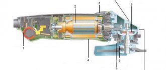
The device of the grinder
Regarding the structure of the grinder, everything is indicated in the figure and no explanation is required. With the help of driven and driven bevel gears, rotation is transmitted from the electric motor to the gearbox shaft.
Commutator motor malfunctions
Possible reasons for the breakdown of the electric motor of the angle grinder are as follows:
- wear of the rotor commutator;
- wear of graphite brushes;
- stator winding burnout;
- burnout of the rotor windings;
- lack of contact connection between the ends of the stator windings and graphite brushes;
- mechanical damage to the cable wire at the base of the plug;
- mechanical damage to the wire along the cable length;
- capacitor failure,
as well as other possible reasons associated with some kind of break in the electrical circuit.
Mechanical breakdowns and their elimination
Mechanical failures of angle grinders include the following.
- Worn motor armature bearings. Typically, when the bearings wear out, you may experience strong vibration while the machine is operating. In addition, grinding and other noises may be heard. Sooner or later, the bearing will collapse, and the spilled balls will fall on the gears of the gearbox. If this happens, then in addition to the bearing, the gears will also have to be replaced. Of course, it is better not to wait for this problem, but to replace it at the first sign of bearing failure. How to get to this part of the angle grinder was described above.
- Worn ball bearing or plain bearing of the gearbox. As in the previous case, when you turn on the device, vibration will be felt and noise will be heard that is unusual for the normal operation of an angle grinder. To prevent further damage to the gearbox, it is necessary to replace the faulty part.
- Reducer gear wear. Gears wear out quickly due to insufficient lubrication. For the same reason, the gearbox heats up. It is necessary to monitor the condition of the lubricant inside the gearbox and change it if necessary. How to disassemble the gearbox was described above. You need to use lubricant specially designed for angle grinder gearboxes, and you can buy it at points where this tool is sold. If for any reason the teeth of at least one gear are broken, then the entire set of gears (a pair) needs to be replaced.
Mechanical faults can also include a broken shaft lock. In order to replace the retainer, you will need to disassemble the gearbox and remove the large gear.
Results
When you find the desired contact using a multimeter, you can make the connection. For clarity, I recommend that you watch the video below. It talks quite well about solving problems with the stator. There are also detailed instructions on how to deal with part malfunctions.
How to connect a power tool? This question very often arises when repairing power tools when there is no electrical circuit, the device is partially or completely disassembled, disassembled and, in addition, has been subjected to repeated, inept repairs.
Wires stick out in different directions, some of them are connected to each other, the ends of others are exposed. It would seem that it is impossible to understand this chaos, in which there is no logic.
In fact, you can connect any electric motor correctly and without problems, even without knowing the circuit. You just need to know its type, design features and at least the basics of the theory.
I’ll show this using the example of connecting a Macita3612C router.
It seems that it is impossible to understand this chaos of wires without a diagram, but believe me, this is not so. Moreover, some wires can be dispensed with, while others are simply not needed.
Sometimes, when repairing or restoring the functionality of a power tool, it becomes necessary to connect the device to the network while maintaining all the functionality that the power tool originally had, but only wires stick out from the body, quite a lot of them (in my case 6), and the electrical circuit can’t be found anywhere . What to do? In fact, everything is not so scary and difficult.
A distinctive feature of a commutator electric motor is the commutator unit.
It is not at all necessary to know what and how was done initially. In order to connect the electric motor of the tool, you need to do the following:
- Find the supply circuit.
- If necessary, connect capacitors.
- Connect the switching device.
Method for finding power wires
In hand-held power tools for any purpose, as a rule, a universal commutator motor (UCM) is used. This versatility is very conditional and only means that the engine can theoretically operate on direct or alternating current. In practice, during repairs, this feature cannot be used; it is more important to know the circuit diagram of the UCD. By looking at which you can draw an important practical conclusion.
One of the bundle of wires entering the motor housing must certainly be connected to one of the stator windings, and through it to the contact pad of the brush.
To make sure of this, you need to unscrew or remove both plugs of the brush holders and remove the brushes. Then, touching one multimeter probe to the contact pad of one of the brushes, use the other probe to ring all the conductors in sequence. If the desired wire is not found, move to another site. In the end, the right guide will definitely be found.
In this case, it is convenient to use a multimeter with an audio signal. Depending on the design features of the device under study, the resistance in some circuits may be very small and this can be misleading.