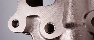
Categories of metal processing purity
Roughness classes allow you to determine the quality of a product and the possibility of its use in a particular area. The following surface cleanliness classes exist:
- Rough - the result of work with a simple hand tool or the primary stage of machine processing. Rough parts have obvious irregularities that are visible to the naked eye.
- Semi-clean - occurs during manual processing with a more precise tool or during finishing machine processing. Visually, the irregularities will be barely noticeable.
- Clean - this surface can be achieved by using a grinding tool, but unevenness can only be seen with the help of special equipment.
- Very clean - a reference class of processing, when there are almost no irregularities, achieved through high-precision grinding.
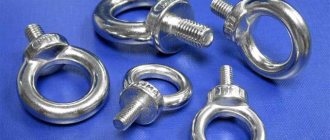
Interesting: Types of metal carvings and their classification
Surface roughness classes
Application rules
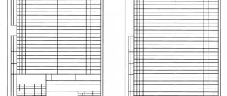
There are quite a few rules by which roughness designations should be indicated. To begin with, the drawing is drawn with thin lines, after which roughness symbols begin to be indicated, and only then the contour is highlighted with thick lines. In order to correctly read roughness in a drawing, you should know the rules for its application, as well as what the applied roughness icons look like.
Designations of surface roughness in drawings
The basic rules by which roughness can be indicated are the following:
- The designation may be indicated in the form of a tick, which cannot be applied upside down to the plane line of the part. However, it is worth considering the presence of axes of the center of rotation, since in this case opposite surfaces can be used to apply the required dimensions and classes.
- The master must take into account that the necessary information is often indicated on the remote shelf.
- An important point is that the roughness designation can only be applied on the side of the part from which the cutting tool can be brought. In a similar way, the technologist indicates the features of the surface formation work.
- Quite often you can encounter a situation where the entire surface of a part has the same roughness. In this case, this parameter is indicated in the drawing in the upper right corner; it is not applied to the part. Also, roughness parameters for all surfaces can be indicated on the drawing, and for special ones they are indicated directly on the surface itself.
- Indicators are also applied to the threaded surface. Often the threaded surface is indicated on a leader with other parameters due to insufficient space.
All these and many other symbols are indicated by applying them to the surface or callouts, in the right corner of the drawing, taking into account GOST 2789. It is worth remembering that indicators are also set for the threaded surface in accordance with GOST 2789. The use of certain designation methods depends on the characteristics drawing, as well as the decision of the engineer who carried out the development. However, compliance with established standards allows the master to quickly understand the new drawing and the specified standards.
Surface roughness designation
Surface structure marking
In the drawings, the roughness designation is made for all surfaces of the product, with the exception of those whose roughness is not indicated by the requirements. In the design documentation, the marking is indicated by a special icon, which has an additional shelf and other clarifications. If the processing method is not indicated, then the icon is shown in the drawing without a shelf.
Rules for applying roughness marks on drawings
Signs to indicate surface roughness depending on the type of processing
Main sign
The main icon that corresponds to the standard condition for normalizing roughness. Used when the method of roughness formation is not regulated.
Mechanical processing
This mark is used when the surface is obtained as a result of mechanical processing. For example, when grinding, turning, polishing, etc. This designation may not indicate a specific type of mechanical effect.
Designation for casting or stamping processing
This designation is used when the surface is obtained without removing the layer by mechanical processing. For example, casting or stamping. It is also not indicated what work was carried out on the part.
Examples of surface roughness designation
In order to understand the designation of surface roughness in drawings, you need to consider a few simple examples:
- √(Ra 3) – the number “3” indicates the highest permissible value of the parameter. Depending on the number, the characteristics will also change; it is logical that if “3” is replaced with “80” or “10”, then during manufacturing the part will achieve the desired value.
- √(Rz 40 min);√(Rz 20min) – Rz 40min and Rz 20min indicate the lowest value of the parameter. This designation is used when, in order to properly perform its functions, the part must not have a too smooth surface.
More detailed information about designations can be found in GOST 2.309-73.
Symbols for directions of surface irregularities
- √(=Ra1) – irregularities are directed parallel to each other.
- √(⊥Ra1) – perpendicular direction.
- √(X Ra1) – directions intersect.
- √(М Ra1) – arbitrary direction.
- √(С Ra1) – circular direction.
- √RRa1 – radial direction relative to the center of the surface.
- √PRa1 – irregularities are directed randomly.
Interesting: Types and equipment of metal slitting
Designations for the direction of surface roughness in drawings
Surface roughness designation
Surface roughness is indicated in the drawing for all product surfaces made according to this drawing, regardless of the methods of their formation, except for surfaces whose roughness is not determined by the design requirements.
The structure of the surface roughness designation includes a roughness sign, a sign flange and other additional instructions. When a sign is used without specifying the parameter and processing method, it is depicted without a shelf.
The height h should be approximately equal to the height of the dimensional numbers used in the drawing. The height H is equal to (1.5…5) h. The thickness of the character lines should be approximately equal to half the thickness of the solid main line used in the drawing.
Control methods
Roughness can be assessed in different ways and at different stages. The most accessible assessment method is visual, but it does not provide high accuracy, therefore, specialists have to resort to other methods. For assessment the following is used:
- Comparators.
- Electronic devices.
- Microscopes.
- Profilometers.
Surface roughness samples
There are two assessment methods:
- Element-by-element – in this case, individual indicators are compared.
- Complex – the finished product is compared with the standard.
Examples of surface roughness designation
| Graphic representation of roughness | Explanation |
| The numerical value of the parameter is indicated, corresponding to the coarsest permissible roughness, i.e. the highest limit value for the parameter Ra, Rz and Rmax. The values of the parameters Ra, Rz and Rmax are indicated in µm. | |
| The minimum value of the roughness parameter is indicated. The method is used in some cases when a surface that is too smooth is unacceptable for proper functioning. | |
| Numerical values corresponding to the largest and smallest limit values of the standardized parameter are indicated. The value indicated above corresponds to the coarsest permissible roughness. | |
| The nominal value of the parameter with maximum deviations from it in % of the nominal value is indicated. The method is used mainly for samples for comparison of surface roughness or for reference parts serving the same purposes. | |
| The roughness of the surfaces forming the contour is indicated. | |
| The type of surface treatment is indicated. Indicated only in cases where this type of processing is the only one that provides the required surface quality. |
It is allowed to use a simplified designation of surface roughness with its explanation in the technical requirements of the drawing. In simplified notation, lowercase letters of the Russian alphabet are used in alphabetical order, without repetition.
What roughness parameters exist?
Let's consider what qualities and roughness parameters are.
Qualities are a single set of tolerances that are characterized by constant accuracy for all sizes of a certain range. GOST 2789-73 establishes 20 qualifications.
The parameter table includes the following values:
- Ra and Rz are indicators of the arithmetic mean deviation of the profile and the height of profile irregularities.
- Rmax – maximum profile height.
- Sm – average value of the roughness pitch.
- S is the average pitch value of the local protrusions of the profile.
- tp – relative reference length of the profile.
Designation of roughness when grinding shafts etc
The designation of roughness when grinding shafts and other parts has changed many times:
Since 2012, the indication “Ra” under the roughness sign is mandatory. Previously, if, for example, when grinding a shaft , we saw only the number 0.32 above the roughness sign, by default it was assumed that this designation meant Ra0.32.
The sign a denotes roughness, the method of obtaining which is not determined by the designer. The sign b indicates surfaces that need to be processed by removing a layer of metal (milling, grinding , etc.). Surfaces indicated by the sign c are obtained without removing the metal layer (forging, casting, etc.).
This sign denotes the roughness of equally processed surfaces that make up a closed contour (for example, all faces of a parallelepiped).
Surfaces with unmarked roughness must be made with the roughness indicated in the upper right corner of the drawing.
We grind shafts
At our enterprise you can carry out not only grinding of shafts and grinding of other parts, but also take advantage of a wide range of metalworking services to order according to the Customer’s drawings or samples. You just need to call or send your drawings by fax or email!
- tolerances;
- planting;
- Tolerances on shape and location.