Spot welding is one of the most common in everyday life. It allows you to connect metal parts quickly and reliably, and there is no need for any special welding skills. Another important advantage is its simple equipment, which is quite possible to make yourself. Considering the fairly high cost of such units, the issue of independent production of this device becomes very relevant.
What is spot welding
Spot welding is a common welding method based on connecting two products by heating using electric current.
The properties of the weld depend on several factors:
- Properties of electrode wire;
- Welding current;
- Surface cleanliness of welded structures;
- The force of compression between products.
High-quality welding is highly valued and equally highly paid. It features high performance and a wide range of applications.
Successfully used in the following industries:
- Automotive industry;
- Shipbuilding;
- Aircraft manufacturing;
- Mechanical engineering.
Homemade welding device
The resistance welding machine is an indispensable device. Such units should be in the “arms” of every master. In the garage, at the dacha, in the workshop and even at home, there is always a use for such units.
The resistance welding machine is quite expensive, so its production looks very attractive. Firstly, you can be proud and show off this device in the future. Secondly, homemade manual resistance welding is much cheaper.
It is also important that it is quite possible to assemble such a device yourself from scrap materials, which will further reduce the cost of the unit. In addition, the assembly is not very difficult and almost anyone can handle it. In this matter, it is important to strictly follow the instructions.
Schematic diagram of a spot welding machine.
It is worth noting the following: the manufacturing task is greatly simplified if you make a spotter from a welding machine that has stopped standing. In this case, there will be almost all the necessary details. As a result, assembling a new unit will not cause any difficulties.
Another common method is to create a device based on a microwave oven. In this case, the main thing is to correctly connect the transformers, especially if there are several of them.
It is enough to understand the basic diagram of resistance welding, as well as understand the principles of its operation, in order to be able to manufacture a device not only according to ready-made drawings, but also according to your own. In the latter case, it becomes possible to create equipment that fully satisfies all the requirements of the master.
With the right approach, you can make welding better than models sold in stores. This is due to the fact that your own product will take into account many parameters that are important to the master. We are talking about the design of the pliers, the size of the body, as well as the power and weight of the device.
At home, resistance welding is used for welding cars, metal sheets, wires, small household appliances and much more.
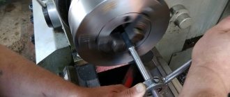
How spot welding works
This type of welding has characteristic features that must be taken into account when operating the equipment. When current is passed through electrodes through overlap welded metal structures, heat is generated, which rapidly heats and melts the parts.
The metal parts are pressed tightly with the electrode wire, due to which they are tightly connected to each other.
Defects and reasons for their occurrence
Multi-spot welding is a popular method that is used in factories and at home. Using it, you can connect thin metal products, and the seam itself is durable and of high quality. However, even during this welding method, some defects may occur that can negatively affect the quality of the result.
Among the main defects are:
- Burn-through . This defect takes the form of a hole that occurs in both parts. The fused edges come off easily. Overheating and dripping of the metal can occur due to several conditions - the use of high current, long pulse duration, excessive compression force. To prevent burn-through, it is recommended to reduce the current and pressure.
- Metal splashing and spreading . With strong compression or when using a long-term weak pulse, the metal can come out of the core, and voids appear in its area. During the working process, metal splashes out in the form of sparks that fly out from points. Up to a certain limit, splashing does not cause any particular harm to the quality of the seam, but still the presence of this factor reduces the strength of the welded joint.
- Lack of penetration . Failure to warm up the core can occur for a number of reasons - weak degree of impulse applied, insufficient compression force, weakening of the pincers. Lack of penetration can occur in cases where welding points are located nearby - the neighboring point acts as a shunt through which part of the volume of electrical energy can pass. This means that it will not be used to melt metal.
- Reducing welding diameter indicators . Insufficient melt area may appear in cases where the pulse is applied too short or the welded elements do not fit too tightly. In these situations, there may be one or more microalloys at one point; in total, they are much weaker than a solid point.
How to fix defects
Contact or non-contact spot welding must be performed in accordance with a specific technology. But still, this method has some difficulties that can lead to various defects. And difficult and inaccurate diagnostics do not give an accurate picture of the quality and type of the resulting welded joint.
If after welding the above defects are identified, then to eliminate them you can use the following recommendations:
- re-boil the point;
- drilling and subsequent welding using a semi-automatic machine;
- if external splashes of metal are noted, they can be carefully cleaned off;
- hot spot forging;
- installation of a welded or blind rivet.
Pros and cons of spot welding
Spot welding, like any other type of welding “art,” has a number of advantages and disadvantages.
About the pros:
- Smooth and precise seam;
- At the welding site, deformations are insignificant;
- There is a possibility of automatic operation;
- Welding using this method does not have a detrimental effect on human health;
- Speed of work;
- Thick material can be joined;
- Ease of use.
With such significant advantages, there are also disadvantages. Briefly about them:
- Area of application – joining of overlapping sheet parts and core materials (e.g. wire)
- Low tightness compared to welds using electrode wire;
- The metal must be cleaned before welding;
- Experience setting up equipment is required.
Areas of application of resistance spot welding
The use of spot welding most often occurs in domestic conditions. It is used when it is necessary to quickly obtain a reliable connection of metal elements. You don’t have to be a professional to do this; you can make the equipment yourself.
Most often, resistance seam spot welding is used for joining:
- parts from corrugated sheets (when carrying out decorative and construction roofing work);
- pipes capable of withstanding any strong pressure, intended for use in aggressive environments, etc.;
- copper (for example, in vehicles, railway rails, car components).
welding equipment
Let's talk about equipment, what you should look for when choosing, and a number of other subtleties.
Safety precautions
Spot resistance welding is a relatively safe type of work and does not require special safety measures. At the same time, we should not forget that devices designed for this type of welding are connected to a high-voltage network and require compliance with all rules for operating in such networks.
A specific danger characteristic of this type of work is the splash of molten metal, which can be a consequence of welding in the wrong mode or poor cleaning of the surface of the parts being joined. To protect against this phenomenon, it is necessary to have a welder's mask. When welding galvanized metals that emit harmful gases, it is necessary to provide the work area with effective exhaust ventilation.
How to choose
When choosing welding equipment for spot welding, 7 important parameters are taken into account that affect the goals and acceptable limits of the welding machine:
- Welding method
- Operating mode
- Voltage
- Maximum Incoming Current
- Allowable material thickness
- Control method
- Additional options
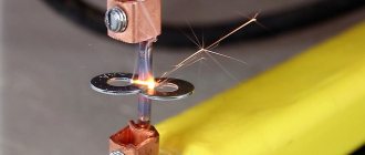
Principle of operation
The physics of the process is elementary and is known even to a schoolchild. We all know that when electric current flows through a conductor, the conductor heats up. The greater the current, the greater the heating. In resistance spot welding, the parts being welded act as conductors. They are placed on top of each other, clamped with special electrodes and voltage is applied.
Since the resistance of this section is negligible, even at a voltage of several volts, currents of hundreds and thousands of amperes flow (depending on the capabilities of the power source). Currents of this magnitude bring the metal of the parts to strong heating and softening, which, with high pressure from the electrodes, creates conditions for mutual diffusion.
The task of the welding machine comes down to creating a sufficient force to compress the parts with the electrodes and supplying high currents at the time of welding the parts. It is also necessary to ensure effective cooling of the electrodes, otherwise they will simply melt, because the same current flows through them as through the parts being connected.
Types
Portable equipment is small in size, no more than 18,000 cm3. Small equipment equals small power.
- The maximum thickness of the metal sheet material being welded is no more than 5 mm. Such devices are suitable for welding body parts or large metal structures. Such equipment should weigh no more than 16 kilograms.
- Stationary equipment is used in production. Compared to portable welding machines, they are large in size (up to 300,000 cm3) and weigh up to 1 quintal. High power allows you to weld sheet metal with a cross-section of no more than 10 mm.
Advantages and disadvantages of resistance welding
The main advantage can be considered the ability to fully automate the process. This circumstance contributed to the introduction of this method on machine-building conveyors. The highest labor productivity can be achieved by spot welding in combination with industrial robots. In addition, productivity gains are achieved by introducing multi-point machines. This type of welding allows:
- do without highly qualified welders;
- ideal for joining thin sheet materials;
- carry out work without the use of protective gases;
- has a negligible effect on the metal of the product;
One of the advantages of this method is the absence of the release of harmful gases. The last argument can be considered a high degree of fire safety compared to manual arc welding.
The disadvantages of this type of joining parts begin to appear when welding products of complex shapes. While there are no problems with metal sheets, complex products require special forms of electrodes, which is not always possible. Complications increase when trying to create multi-point equipment. It is not always possible to use this welding when welding several dissimilar metals and alloys. In this case, such an advantage as the absence of protective gases works against production.
A significant danger for operating personnel is created by the possibility of metal splashing when a strong current is applied to the electrodes. This is especially true for older cars. Modern welding machines provide a smooth supply of welding current. Even greater safety is achieved by using direct current in combination with software controlled compression force.
Spot welding methods
Welding equipment is divided into two welding methods.
Welding on one side. Spotters are used for this operation; they have several fundamental differences from other devices. There is a manual device used for welding. The one-sided option of welding metal structures is justified if the reverse side of the welded products is difficult to access.
It is more convenient to use the type of welding when it is possible to weld the seam on both sides. This method is used to join sheet materials.
How to prepare the elements?
The preparation of workpieces for processing by a resistance spot welding machine occupies an important place, since the stability of operations and the quality of the resulting joints depend on it. The product for welding is straightened, cleaned, adjusted, tacked or assembled in a special device. A significant thickness of oxide film is removed using special rollers with helical notches, flame heating, shot blasting, shot blasting or vacuum-fractional processing, and capping the welding zone. Workpieces made of low-carbon steel must be degreased with gasoline, acetone or other oil solvents, followed by etching, brushes, abrasive and grinding devices. The treated surfaces are also passivated.
The workpieces can be cleaned only at the overlap or completely. After mechanical cleaning procedures, oxides and dust with abrasive particles should be removed from them. Products coated with metal are usually not subjected to stripping; they are tacked by conventional welding. Small-sized components and workpieces can be welded without tacks by firmly fixing them in spot welding pliers. On large products, tacking by arc welding and subsequent cutting out of tack areas is possible.
Operating mode
Divided into soft and hard. In gentle operating mode, little electrical energy is used, but the welding process takes longer - 2-5 seconds. Thanks to this, electrode rods of a smaller cross-section are used and it is not necessary to press very hard with them.
The hard operating mode uses increased energy, and the process is faster - 0.2-1.5 seconds. High productivity is ensured, but strong compression of the workpieces with electrode rods is necessary. A rod of large cross-section is also required, which exceeds the cross-section of the products being connected.
Electrodes, technical characteristics and features of use
- The quality of welding also depends on the correct choice of the diameter of the copper electrode. The diameter of the connection point must exceed the thickness of the thinnest element of the welded joint by 2 - 3 times.
- By pressing the parts at the moment of passage of the welding pulse, the formation of a special sealing belt near the molten core is ensured, preventing the splashing of molten material from the welding zone. As a result, no additional protection measures are required at the connection point.
- To improve the crystallization of the molten metal, the electrodes must be opened with a slight delay after the welding pulse has passed.
- To obtain a high-quality and reliable weld, the surfaces to be joined must first be prepared, in particular, cleaned of rust.
- The gap between the connection points should provide a reduction in current shunting through adjacent points. For example, for welding two (three) parts with a thickness of 1 to 8 mm each, the distance between the connection points varies accordingly from 15 (20) to 60 (100) mm.
Quality of materials
- Electrodes used for spot welding must provide strength in the operating temperature range, high thermal and electrical conductivity, and ease of machining. These requirements are met by special bronzes containing cobalt or cadmium, cold-rolled electrolytic copper and copper alloys containing chromium, as well as a tungsten-based alloy.
- In terms of electrical and thermal conductivity, copper is significantly superior to bronze and alloys, but 5-7 times worse than them in terms of wear resistance. Therefore, the best alloy for the manufacture of electrodes is considered to be an alloy of the EV type, which is almost pure copper with the addition of 0.7% chromium and 0.4% zinc. In order to reduce wear of the electrodes during operation, it is recommended to use intensive cooling with water.
Voltage
Welding installations are powered by 220V and 380V. This is indicated in the documents included with the welding machine.
Important! It is not recommended to connect devices with a power of more than 5 kW to a household network.
Spot welder controller and various other components
Not long ago I published a review of a board for assembling a simple welding machine powered by ionistors, and today I have a continuation, where I will talk about a much more functional device and, at the same time, assemble a device based on it. I would like to immediately say a big thank you to Vladimir, who sponsored this review and bought all the necessary components for me on TaoBao. We spent quite a long time selecting a relatively optimal configuration option, and below you can read what we ended up with. The review will be relatively brief, but I will try to make it as informative as possible.
In addition to the ionistors and the handle with contacts that were in the previous part, I needed a controller, a power board and other additional parts, and that’s all I actually got.
I’ll start the description with the controller, this is the so-called CPSMC 6Y880, on the product page it is referred to as a fifth-generation controller, it costs $22.72 - link. There is an option without a fan and some other small things, but it’s easier to buy everything at once.
The kit includes: 1. Control board 2. Resistor board for the balancer 3. Encoder board and a pair of connectors 4. Fan and coupler. 5. Encoder with handle 6. Necessary set of wires for connection. 7. Racks for assembling boards into a package
The screen has a visible area size of about 50x40mm, I think many have seen it in other devices. Below it on the power board you can see a pair of capacitors and a tweeter. There was an interesting effect with the squeaker; I usually work at night, and in order not to be annoyed by the periodic squeaking (due to the disconnected ionistors), I tried, as always, to seal it with electrical tape, so it began to squeak even louder.
The power board contains a charger, balancer transistors, a power stabilizer, and an encoder is installed here. The board can be powered with a voltage from 12 to 19 volts, the current consumption depends on the settings and in fact it is not the current that is counted, but the power, since the required current depends on it and the supply voltage, the lower the voltage, the greater the current.
The charger is assembled on the basis of a synchronous converter RT9214, therefore the efficiency is quite high.
The display board also contains a microcontroller that controls the entire device and measures the voltage on the ionistors and the board input.
The field-effect transistor driver for the power switching board is also wired here; the circuit is simple, with several transistors, no specialized microcircuits, which is generally quite normal.
Resistor board, here they are grouped into 2 groups of 5 resistors each, the resistors within the group are connected in parallel, they do not have a common wire, so 4 wires are needed for connection.
There are many connectors. 1. A 5.5x2.1mm socket is used for power supply, to the right is a two-pin fan connector, and to the right is a place for the encoder connector. The encoder can be installed either on the main board or separately, for which the kit included both an encoder board and a pair of connectors, as well as a corresponding cable. 2. Three-pin connector for connecting the board for switching power from ionistors and a two-pin connector for connecting the control button. 3. On the left is a three-pin connector for measuring the voltage on the ionistors, on the right is the terminal block for connecting the resistor board, and to the right are three contacts of the power wires to the ionistors. 4. Accordingly, the terminal block of the resistor board also has an icon notifying that the board can get very hot.
I note that the connections to the ionistors are six-wire, through three the charge/discharge current flows, and through another three the voltage is measured. This solution increases the accuracy of measurement and balancing, and also speeds up the charging of ionistors. The ends of the wires are connected at the terminals of the ionistors or as close as possible to them.
The kit includes a small 50mm fan, all wires except the power ones, stands and an encoder board. In general, the kit is quite well thought out, I was especially pleased that there is a separate board, connectors and cable for the encoder, so it can be installed both on the main board and in any location on the front panel.
I will show the connection diagram later, but for now I will move on to a description of the controller control. At startup, the manufacturer's logo is displayed, then the controller goes into the main control menu mode, albeit in Chinese. To change the language to English, you need to go to the settings menu, top row on the right, switch by rotating the encoder, activation by pressing. Going to the settings menu, go to the penultimate item, click, select English, click again, go down even lower and exit the menu. All.
I'll describe the main menu. 1. Select the duration of the first pulse, range 1-35ms, press the encoder to select, then select the time by rotating, press again after finishing. After turning off the power, this and other settings are saved, which is very convenient. 2. Selecting the duration of the second pulse, range 0-35ms, default is 0, i.e. the second pulse is not produced. 3. Choice of pause time between pulses, range 0-99ms, at zero the pulses are combined into one, i.e. You can set the range of one pulse from 1-70ms. 4. Automatic current control mode. By default, control from the microswitch in the handle is enabled, but if it is not there, you can enable activation by touching the electrodes. This setting adjusts the pause between touch and current supply, range 0.1-5s. 6. Voltage regulation, in fact it turns out that this is the equivalent of current regulation since the current directly depends on the voltage. You can adjust it in the range from 0.1 volts to the maximum battery voltage.
Also displayed on the screen: 1. The voltage of the battery and each of the cells, both in numerical and graphical representation. 2. Overall charge level (green scale at the very top of the screen). There is a nuance here, the jackal displays the range from 0 to the specified value, i.e. is adjusted dynamically, and the filling on the battery icons is tied to the preset battery voltage. For example, if the battery is 5.4 volts, but 2.7 volts is set, then the scale at the top will be full, but on the battery icons it will only be 50%. 3. Board supply voltage. 4. Temperature, although it is not clear what it measures... 5. Battery charge current.
Buzzer switch advanced settings menu
— sound on/off.
The sound is essentially only when rotating/pressing the encoder, or during an accident, so you don’t have to turn it off. Auto
— Not set/set, an incomprehensible setting, since the automatic power supply mode works without it.
Max charging current
- ionistor charging current, adjustable in the range 0-10A, default value is 8A, at 0 there will be no charge (for example, if an external charger is used).
Single capacitor voltage
- the board is designed for a 2S connection circuit; at this point we set the maximum voltage per element, range 2.3-4.2 volts, i.e.
You can use both ionistors and batteries from LiFePO4 to conventional LiIon. The resolution of the installation is 0.01 volts. After installation, we can set the voltage from the main menu from the minimum to the value set here, so there is no chance to recharge the battery. Clear count
- clearing the operation counter, i.e.
how many points we welded. Continuous welding - long-term welding, in contrast to the main 1-70ms, you can force the maximum time to be set to 3 seconds. Language
- language, Chinese/English
Just for the sake of experiment, I connected the board “to a live thread”.
The charge proceeds without problems, it stops at the set value, but of course there is no balancing, since the resistor board is not connected. The charge was set to 2A, since the connected power supply has low power.
By the way, about the power of the power supply. As stated above, the input voltage range is 12-19 volts, the charging current range is 0-10A and the battery voltage range is 4.6-8.4V (two cells in series). Accordingly, the input current is calculated very simply, we take the maximum battery voltage, for example 5.4 volts, the maximum charging current, let's say 8 amperes, then with an input of 12 volts the current will be: 5.4x8=43W 43x1.2(efficiency)=52W 52\12=4.3 A
First, we calculated the charging power (voltage x charging current), then we added conversion losses (in reality, the efficiency is closer to 85-90%, I calculated with a margin), then we divided the resulting power by the voltage of the power source, and obtained the current accordingly. Since the charging process is usually relatively short, it is not necessary to take a power supply with a reserve; then I even did the opposite, but more on that later.
But a new version of the board has already appeared on sale, with more settings, charging current up to 20A, costs $33 - link.
Additionally, the following were ordered: Power transistor board Copper bus bars, included with the transistor board The transistors themselves. Copper terminals.
Copper terminals for screws, two sizes SC25-6 and 16-6 - link The busbars and the screws for fastening them came with the board - link.
Power board. Such boards are sold for different numbers of transistors, with and without transistors, with and without separation of power switches, with output and SMD components, and also only with transistors. In general, you can choose whatever board you want, I’ll tell you about the differences. 1. Board without transistors. Here it is possible to install better transistors, but soldering is quite problematic, although there are options for transistors in the TO-220 package, but usually they have worse parameters. 2. Board with transistors. You don’t need to solder anything, buy it and use what you gave... 3. Board with key separation. Sometimes on some boards you can notice divided polygons for connecting power buses, theoretically they make it easier to diagnose broken transistors, in practice, I think that the transistor will simply break in half and there will be nothing to diagnose, but nevertheless, you can choose such a board, it won’t be worse. 4. Number of transistors. Theoretically, the more the better, but here problems arise in managing them; in my opinion, 12 pieces are optimal, although there are monsters with 32-52 transistors. 5. Additional components on the board. It’s better if they exist; you can always throw them out/short-circuit them. The whole problem lies in the fact that often the controls are extremely simplified, and the board with components allows at least some modification.
We chose a board with 12 transistors, with additional output resistors/diodes, and copper busbars. True, for some reason they gave one more resistors, and one less diodes. Costs about $5.75 including tires - link
The circuit is primitive, the voltage to the gates of the transistors goes through diode isolation, while the gates themselves are connected to ground through 10 kOhm resistors. Those. We charge the gates quickly, discharge them through 10 kOhm, which in my opinion is too much, if I’m not mistaken, then with a gate capacitance of 22 nF the total turn-off time will be about 1 ms. The board was chosen based on the idea of modifying it by installing drivers.
Key transistors. Usually two types are used, in the D2PAK and TO-220 packages, but the latter have a smaller choice and worse parameters, so IRL40SC228 was chosen as one of the “lowest resistance” ones, the stated open channel resistance is 500 μOhm or 0.5 mOhm. They are sold in a tape, but I did not have any hopes that this was the original and new ones, especially after receiving it I noticed that even so there was a small difference between the copies. Bought 24 pieces for $0.62 - link.
Everything matches in size, but there was a small flaw. The board was supplied with copper busbars and 6 bolts, 5 of the same size and one one size larger, while there is a hole visible on the board where the transitions between the sides are located away from the hole for the bolt, but the diameter of the hole itself was made the same as the others. At the same time, in the photos of other boards everything was done correctly, apparently there was an error in indicating the diameter.
Next, I cut a piece of tape for 12 transistors, the second half “in reserve” or for some modifications...
They look like the most ordinary transistors, new, but on the case you can see small chips and scratches, which transistors in the tape should not have.
Moreover, even if you take 12 pieces in a row, it turns out that they are different in appearance, one even showed a fingerprint, although this is not certain, he suddenly left it himself, but it is very unlikely.
The difficulty of installing such transistors is that for this it is desirable to have a hot-air soldering station with bottom heating; I once reviewed it.
But before soldering all 12 transistors, I decided to test one of them first. Of course, in this case, the check was simple, especially since checking “to the fullest” is very problematic, but the parameters are very impressive. The only negative, in my opinion, is the large gate capacitance characteristic of such transistors.
In the test, I supplied a current of 12 amperes, the gate voltage was 9 volts, and in the end I got: 1. Transistor resistance near the terminals from the case - 0.493 mOhm 2. At the polygons near the case - 0.626 mOhm 3. Flange-polygon section - 18 µOhm 4. Section test terminals - 92 µOhm.
As you can see, the resistance corresponds to the declared one, while the largest contribution to the total drop comes from the terminals-landing area, so I used a little more solder in this place than I should. The calculated total resistance of the board is 55 µOhm, which at a current of 400-500A will give a drop of 22-27 mV or a dissipated power of only 9-13 W, although we are talking about static mode here.
But in addition to the power part, it was necessary to connect the handle with contacts with something, there were two options: 1. Remove the wires from the housing 2. Install a connector.
With the first everything is clear, but on the second point it is noticeably more complicated, they usually install terminals from welding machines, but “we are not looking for easy ways” and I wanted to use something more elegant.
To begin with, just a wire, super soft, in silicone insulation, with a cross-section of 7AWG or 10.5mm.sq. in our opinion. Was purchased in case something goes wrong and there is not enough current. I didn’t even begin to count the number of veins, and the core (core) and the shell clearly stand out, perhaps they are twisted in different directions. This cable costs $3.16 per meter of one color (red or black) - link. Moreover, on the page there are wires of different colors and cross-sections up to 2AWG (33mm.sq.)!
The wire is really cool, I recommend it.
But as I wrote above, I wanted a beautiful and detachable connection, for which I ordered a set of a male/female connector and a cable. This connector is called Amass AS150U, in this configuration it costs $6.04 + 4.46 = 10.5 - link The wires here are thinner, 8AWG or 8mm.kv, the ends are tinned, but what is useful, in addition to the power contacts, there are also four auxiliary ones that can be used to connect a microswitch and possibly backlight.
The wire is also very soft, the insulation is of course silicone.
Why was this option chosen and not the usual terminals from a welder? The fact is that the current for which this connector is designed is stated to be 140A continuously, while the resistance is stated to be 0.4 mOhm, which is comparable to the same terminals of welding machines.
But this option both looks neater and is more pleasant to use, especially since it allows you to immediately connect 6 contacts, two power and four additional. Sold in the versions of a plug or socket for a cable and, accordingly, a plug or socket for a device, the part with the cable has a flexible lead.
The contact group is different, one of the contacts has a plastic insert, I will assume that it is positive, then when connecting, the common wire will always be connected first. On the case there is a marking indicating the company and type of connector, as well as a designation of the polarity of the contact, unfortunately yellow on yellow is difficult to see. The 8mm.kv wire fits perfectly into the contact, the 10mm wire fits in with difficulty, literally tightly.
While working with the connector, some difficulties became apparent. The idea is that after soldering, the terminals are pressed into the plastic part, which is why they are separate, although there is an option where they are already installed. But it’s not so easy to hammer them in there, so when soldering, leave a little space to get closer to the middle with something that can be used to hammer the contact inward, otherwise if you hit along the edge, the contact may become skewed. Later I will show the established contacts.
I think many of you are familiar with the popular XT60 connector; for example, I put it next to the AS150U, I think comments are unnecessary 
Initially, I planned to cram everything into a case that was already used in two of my devices, an LCR meter and an adjustable power supply, but alas, the packaging would be too tight, and the power supply would have to be made separately. As a result, I bought a larger case from one of the local online stores; in addition to the size, I needed the case to have a stand to lift it while working.
The choice fell on the relatively expensive (about 11-12 dollars) KH-34-4 with dimensions 240x210x100mm. At first I liked the case, there were screws for connecting the halves, not self-tapping screws, a lot of racks for boards and even special grooves. But during the assembly process it turned out that the upper and lower parts were bent “belly” and after assembly they remained that way, and in general the structure is somehow frail, and the stand leg is very difficult to extend. In general, I don't recommend it.
A power switch with LED indication, a fan grille, as well as transistors and diodes for modifying the power switch driver were immediately purchased there.
Oddly enough, the biggest problem in the assembly was the installation of ionistors, especially considering that the bottom of the case is not flat, which is why the manufacturer even made the stands of different heights. The middle part is relatively flat, the sides have a slight rise as a design element. As a result, I took a piece of fiberglass that had been lying idle for a long time, cut it into place, screwed it to the body, degreased it, and glued the capacitors using double-sided soft tape. And although everything is held firmly, later I plan to additionally press it with zip ties.
Attention, in order to reduce the number of possible problems, I recommend discharging the ionistors before work.
The assembly was carried out according to the circuit diagram of the board intended by the manufacturer; just in case, I drew it separately since it is not complete on the page, and also from a different version of the board. Of course, I’m still not much of an artist, but I think that’s enough to figure it out.
And this is what the intermediate stage looked like, I didn’t photograph the full assembly since it is tied to the type of case, so everyone will have their own, I’ll just note a few points: 1. I screwed a radiator to the resistor board, but the resistors had to be aligned before that, I applied thermal paste between the radiator and the resistors . 2. Since the resistor board is the hottest element, it is better to position it so that the air flow from/to the fan passes through it. 3. I placed a power supply on the same line, I used a 40W 12 volt from Sanmim - link, although I wanted to use another one, but this one had mounting holes. 4. The controller board also heats up, so it should not be “in the shadow” of the air flow.
Looking ahead, I’ll say that everything is fine with cooling; the original fan in this configuration is sufficient.
As power wires I used 6mm for the positive pole and 4x2.5 for the negative; it was possible to use 8mm in silicone insulation, but cutting such a wire into pieces was simply a pity. The third photo shows the pressing of the contacts, I had to hammer them in with a small hammer through a screwdriver, ideally I should have pressed them or hit them exactly in the center, but somehow I adapted without this. Of course, this should be done after soldering the wires so as not to melt the plastic of the connector. Then I soldered the signal wires and wires to the backlight LED, but I didn’t install it yet because I couldn’t figure out how best to install it on the handle.
First I wanted to glue the connector on the case, but after cutting off only part of the stops, then I thought that it would probably be better if it were removable and in the end I made a U-shaped pressure plate from the scrap of plastic left after cutting out the window for the display. It turned out great, now you can remove the connector regardless of everything else, it holds very firmly.
Ready to use.
An overlay with a power supply board came out; I wanted to place it closer to the side wall and further from the front panel, but the peculiarity of the case did not allow this. It ended up being too close to the power switch.
The power connector of the controller board was unsoldered and the terminal block was soldered in its place, all the wires connected to the terminal blocks were crimped with lugs. By the way, I didn’t like the terminal blocks on the controller board at all; I would have replaced them with something more normal, but there was nothing suitable nearby in the required quantity.
I didn’t drill a hole for a large diameter bolt in the board, I just used another one. I also connected the wires diagonally, although according to the plan, the blue wire is connected to the middle hole.
Well, that’s exactly what happened. It feels like the front panel is too empty, but in general the look somehow reminded me of some small TV from the late 70s.
At the back there is only a fan and a power connector. For convenience, a regular “computer” connector was used; I have the same ones on almost all my devices.
It's time to check this whole structure in action. Since the ionistors were discharged before assembly, the first step is to charge them. First, the charge current was set to 2 amperes, left over from previous tests, having decided that the new power supply can do more, I raise it to 8A, which noticeably affects the charging speed. I didn’t track the total charging time, about 15 minutes. Judging by the board’s readings, the temperature was a maximum of 51 degrees, but this hardly corresponds to reality. Closer to the set voltage, the current began to drop, almost at the end of the charge it dropped to 0.2-0.4A, and at approximately this value the board balanced the cells. The photo shows that almost at the beginning of the charge the difference was about 15 mV, but towards the end it went to zero, both ionistors are charged to 2.5 volts. Then I experimented and charged them up to 5.4 volts, but at the current stage I decided to limit myself to a lower voltage.
The fan starts operating at a current of approximately 5-6A and turns off at the end of the balancing process.
I think the question will be how long the preparation process will last at the beginning of work. Since usually only additional charging occurs, in reality everything works quite quickly, especially if you set the charging current to 8-10A. When the device is turned off, the discharge of the ionistors proceeds slowly, for example, in the off state, in two days the voltage dropped from 5.4 volts to 5.28.
Since during work it may be necessary to select the welding current, I checked how the board can discharge the battery. In this case, this function is rather a side function, since the balancer does this; it’s just that when the voltage decreases, the response threshold of the balancer also changes and it works as a load until it discharges the battery to the set value. I set it to 4.5 volts, the fan started working and the board began to discharge the battery, in the process a small imbalance appeared, which was also eliminated at the end of the process. I didn’t measure the discharge current, but the discharge from 5 volts to 4.5 took a minute and a half.
During the discharge process, the fan also starts and also turns off at the end.
Temperature conditions. In charging mode with a current of 10A with an initial voltage of 3 volts and a final voltage of 5.4, the control board heats up noticeably, and the main heating comes not from the converter, as expected, but from one of the balancer transistors, although it is more likely a transistor for switching power to the ionistors. For me, this transistor heated up to 80 degrees, then the converter choke went to about 65-70, but charging with a current of 10A in this range is unlikely, especially since before that I tested in the range of 1-5 volts with a current of 8A, it charged without problems.
Initially, I was more worried about overheating of the balancer resistors during the charging/balancing process, but it turned out that in this mode the resistors are almost cold (second photo), which cannot be said about the discharge mode. When the battery was discharged from 5.4 volts to 3 volts, the resistors warmed up to 105-110 degrees, because I think that my idea with a radiator is still not superfluous. the control board was just warm.
In the last review, I complained that I could only weld steel strips, but there were problems with nickel strips even with maximum settings and short wires. Here I will not repeat the previous tests, since I was interested in welding specifically nickel strips. For the test, I first took strips with a thickness of 0.12-0.15mm, but quickly realizing that for this device it was just a toy, I began to experiment with strips with a thickness of 0.2mm, especially since rarely anyone uses thicker ones for welding cells.
To begin with, it turned out that the machine welds such strips without problems, well, almost without problems, or rather with problems of a different nature.
I tried cooking in different modes, usually 20-30ms is enough, but if I “wanted more,” I raised it to the maximum 70ms, although this is already with a large margin, in this mode tarnished colors appear on the tape.
In general, I was playing around, welding the tape to some used batteries and at some point I noticed a strange smell, it turned out that I accidentally welded through the negative contact of the battery, in the second photo you can even see a little bubble of liquid, which began to little by little come out of the battery. Those. It turns out that you can get significantly more than you need for normal work.
Since it turned out that there was enough power even with a reserve, I moved on to extended tests, and in simple terms, I started trying to weld everything.
A plate of galvanized iron, 0.65 mm thick, came with some kind of fan. I welded strips of tape 0.15 mm thick and I can say that it also welds with a reserve of current, also in the photo you can see an attempt to weld two strips of nickel tape to each other, there you generally need to set the pulse time to about 10 ms and the voltage to 5 volts
Moreover, it heats up so much that traces appear on the reverse side, but I was a little overzealous during the experiments.
This is an attempt to weld a 0.55mm steel plate to another similar plate, but alas, the device did not work with this option, however, this is already extreme. The photo shows two sides of the plate, I think if I had tried to cook the “sandwich” on both sides, I might even have welded it.
Again, a 0.15mm thick nickel strip, but here we tried to work with a massive base, in this case, side cutters, and this test passed with a bang; it took a decent amount of force to tear off the strip, but in the end the strip itself broke.
And here are some oddities that I didn’t quite understand. In fact, all these oddities appeared before, but in this test they became more obvious. The thing is that in many tests during welding, one of the two contacts heated up much more, i.e. I applied the contacts, current flowed, for a short time one contact point became hot, but the other did not. Moreover, almost always it would be the same contact and also almost always negative. At some stage I was interested in this, I thought that it was a matter of polarity, I changed it, but in the end the cooking became the same, I twisted the wires more conveniently but respecting the polarity, and after a while everything again became the same as it was, negative contact during welding warmed up better.
But in fact the problem lies even deeper. During welding, it often happened that the tape that was welded with the negative contact was tightly welded to the base, while the second point connected to the plus was also tightly welded, but to the welding contact... I tried to sharpen the contacts in different ways, both with a trapezoid and a hemisphere, but after 7-10 welding attempts, the contact still returned to a flat shape. Moreover, if you open the welded contact from the tape, then copper remains on the tape.
It turned out especially clearly in the example of a nickel tape and a piece of DIN rail; here the contacts were almost not welded to the tape, but it is clearly noticeable that one point of the pair is clearly different from the other.
Here I’m talking about the welding points and the red “plus” ones, they were welded almost in a row, while the “minus” ones were welded to 5 points, and the “plus” ones could be torn off with your hands without even making an effort.
If it’s difficult for me to say anything specific about the polarity due to lack of experience, and searching on the Internet did not give anything specific, then I’ll say about the contacts themselves, those that come with the handle are normally suitable for working with batteries, but if the current is exceeded, then they start to overheat. It is also possible that the problem of them “sticking” to the tape is partly related to the quality of the contacts. I started looking for what they actually use and while searching on TaoBao I came across some expensive contacts, and if some cost $23 per pair (first and second photos), then it turns out contacts cost $40 per pair (third photo)…
But in general, for the pen that I use, there are noticeably more budget options, for example, there is a lot with a bunch of options, processed and unprocessed (as I understand it, this means thinning at the end), Chinese and Japanese, 100 and 500 mm long - link.
There were also electrodes of “local” production, and judging by the statements -
resistance spot welding electrodes made of dispersion-strengthened composite material (DSCM). The service life is 5 times higher than technical copper and 2-2.5 times higher than chromium bronzes (BrKh and BrKhTsr).
Also, during the search, I came across flux to make working with copper tape, which has begun to appear recently, easier. Just a friend who deals with batteries spoke about her and complained that she was more “gentle”.
Already upset, after a while I decided to experiment again. I came across information on the Internet that it is better to cook when the current is higher and the pulse time is shorter, I basically tried to do that. But then I thought, why not try the other way around, reduce the current, but increase the time. I set the voltage to 4.0 volts, the pulse to 35ms and found out that it cooks very well, at the same time it cooks both contacts and they do not stick. I made a pulse of 10, a pause of 50 and a second pulse of 35, it became even better, but when I raised the voltage to 4.5 volts, it worked the same way, but the contacts began to stick.
Red - five contacts 4.0V mode, 1/99/35ms (later I’ll explain why it’s so tricky) Green - four contacts 4.0V 10/50/35ms Yellow - six contacts 4.5V 10/50/35ms.
It was welded thoroughly, the tape was torn, but the welding points held perfectly.
Before drawing conclusions and describing the features of the device, I want to answer the question that will probably be asked, how much does it all cost in the end. Let's do the math. 1. Ionistors - $5x2=10 2. Handle with welding contacts - $13 3. Controller - $22.7 4. Transistor board with copper buses - 5.75 5. Transistors - $0.61x12=7.32 (there are cheaper options) 6. Power supply - $10 ( if you take a used one, then about 5) 7. Wires and connector - $10.5 8. Terminals - about $0.3 9. Housing + power switch + fan grill - $12 10. Small fasteners, wires and other small items, well, let's say $0.5 Total excluding delivery - $92
The situation with delivery is complicated, both in terms of the actual price for it and the choice of sellers, it’s more economical to buy everything from one, then delivery in China is cheaper, but sometimes something is cheaper from another seller and you have to consider how it will be more profitable, for example, this was the case with transistors, one has 0.61, the other 0.54, but it was more profitable to buy at 0.61. What adds most to the price is the delivery of ionistors, they are heavy, and there is an option for 5 but used ones or 6.5 new ones, I use used ones.
About the nuances.
Above I wrote about some of the features of setting the pulse and pause time, while in the last test I did the 1/99/35 mode. The thing is that the microswitch operates too early, when the pressing force is not very large and due to the “rustle” of the contacts they are welded. In the process, I tried to disable this function and use the auto-detection mode of contact pressure with a delay of current supply of 1 second. It became much better, I pressed it securely and only then the welding current turned on. But then I realized how I could do it even better. We make the first impulse minimal, then a pause, then a full one. In this case, it turns out that the first impulse “grabs” the contacts a little, and only then cooks them.
And of course, conclusions.
I really liked the controller and the resulting device. At first there were difficulties, I described them, but then it turned out that the fault was a lack of practice and I just had to adapt to the device. In addition, I recommend having a supply of tips and should not skimp on them.
What I liked: Large selection of settings, you can change both the welding current and the pulse time within a very wide range. In addition, you can use control from a microswitch and an automatic mode for closing contacts with a pause. The controller also has a powerful charger, a balancer function, the ability to force ionistors to discharge, support for working with batteries, and the ability to turn off the charger. Correct fan control; it does not irritate during operation, as it turns on rarely and only when necessary. The purchased transistors correspond to the declared resistance in the open state, the powerful connector also turned out to be up to par, and it’s convenient to use and there are enough contacts even to connect the backlight. Now there is even an excess of welding current; for normal operation I had to use a voltage of 4-4.5 volts instead of the maximum 5.4-5.6.
What I didn’t like: Power board with transistors, there is no driver on it, and although it is cold in operation, I understand that discharging gates through 10kOhm resistors is somehow not very nice. There is no mode switching mode with external contact and auto in the menu of the board, immediately install a switch that turns off the microphone of the handle. There were problems during welding, when one contact was welded normally, but the second was not, it turned out that there was too much welding current. It is better to replace the terminal blocks on the controller board with better ones.
In general, I can say that the device cooks, it cooks quite well. You can, of course, say that it is easier to make it based on a transformer from a microwave, but the one under review has at least one advantage, it only needs 12 volts at a current of up to 5-6A, it will work even with a 12 volt 1A power supply, but the charging current is no more than 2 amperes , accordingly, you can use it even in an “open field” with power from a power bank, or even in a car.
This is all I have for now, but I will continue to experiment.
Allowable material thickness
A parameter indicating the maximum thickness of a part that welding equipment can weld. Ignoring this parameter, the welding quality deteriorates significantly. It is indicated either by a common section, for example “2 mm”, or by two numbers, “1+1 mm”.
Industrial machines have the ability to weld three metal sheets together, then the cross-section is designated “1+1+1 mm”.
Control method
The cheaper the device, the less functionality and the more difficult it is to control the device. The cheapest versions do not have the ability to adjust the current strength - it is the same and always maximum.
Needless to say, you have to work manually. Before working on such a welding machine, it is advisable to “break in” it on rough sheets, and then start working.
Numerical control makes the job much easier. The operator indicates the type of connection to be processed, and the “brains” of the equipment independently select the necessary operating modes. The welder only needs to bring the electrodes to the welding site. Of course, you have to pay extra for such convenient functionality.
The essence of the process
Resistance welding, which also includes the spot variety, is performed by heating the metal with a current passing through it. The current comes from the electrodes and acts on a specific point due to slight deformation of the surface under the influence of the clamps. Due to its simplicity, spot welding is used in industry much more often than similar types of resistance welding.
The possibility of using spot welding is practically unlimited. Features of the process itself make it possible to reduce the cost of manufacturing the final part.
Spot cooking occurs under certain parameters:
- exposure time for 0.2-2 seconds;
- low mains voltage - 2-5V;
- high current when welding - more than 1000A;
- compressive force at the welding site up to several hundred kg.
Reliability and accuracy of cooking depends on many parameters. First of all, the quality of fastening is affected by the surface area on which welding work will be performed. The second factor that significantly affects the quality of the weld is the parameters of the welding current and the duration of the work. If fairly thin materials are welded, then one force is required, but in the case of welding on thick material, completely different forces will be required.
Additional options
If the device performs regular, long-term work, the presence of a cooling system should be taken into account. Devices with water cooling and a radiator last much longer than their counterparts without cooling.
For full operation, the spotter requires a gun and a reverse hammer. Also, all welding machines require copper electrodes as consumables. If the equipment weighs more than 13 kg, then it should purchase a trolley for easy transportation on wheels.
Flaws
- For a reliable connection, experience is required to make a high-quality spot seam;
- Welding requires a lot of space, since the mesh occupies a large area.
Types of reinforcing mesh
Meshes are divided according to two main parameters: the location of the reinforcement bars and their diameter. In turn, according to the type of arrangement, there are meshes with the arrangement of working rods in one direction and distribution ones perpendicular to them, and the second option is when the working rods are distributed in all directions. Based on the diameter of the reinforcement, there are light varieties, the thickness of the rods in which is up to 12 mm, and heavy ones, in which the rod is 12 mm or more.
Fittings with a diameter of 12 mm
Dimensions and specifications
When automatic mesh welding lines are used or the mesh is welded manually, it is important to maintain the correct dimensions of the product. The following types with certain characteristics are distinguished:
- Heavy mesh, the working rods of which are located in the longitudinal direction. Their diameter is larger than the distribution rods.
- Heavy mesh, the working rods of which are located in both directions.
- Heavy mesh, the working rods of which are located in the transverse direction. Their diameter is larger than the distribution rods.
- Lightweight mesh, the working rods of which are located in the transverse direction.
- Lightweight mesh with offset working rods.
Best models
According to many people who work closely with welding equipment, the following models should be noted.
| Name | Description | Price | Advantages | Flaws |
| Caliber SVA-1.5 AK | The best price/power option, but not for “garage use” | 13890 rub. | The welding process goes smoothly No machining required Powerful return spring | The overhead console is overheating Heavy Heavily loads the 220V network |
| FoxWeld KTP-8 3098 | Popular when working with large metal structures | 15560 rub. | Large carrying handle Small-sized Increased current power when welding | Backlash Loads the network Heavy Unregulated power |
| Spotter FUBAG TS 2600 38 666 | Suitable for car body repair | 32620 rub. | Overheat warning Four different operating modes | Heavy Expensive Unregulated current |
| Spotter RedHotDot HAMMER IT 275116 | Notable for the presence of numerical control. Suitable for use in garage conditions. | RUR 30,168 | Does not load the home network Small-sized Large melting and welding depth | High price Heavy - weighs more than 16 kg |
| FoxWeld MTP-25 3373 | An excellent option for production conditions. | 67900 rub. | Easy to operate Durable The pliers are compressed using a pedal | Very expensive Special installation required Constant sharpening of electrodes is required |
| WIEDER KRAFT WDK-6000 | An acceptable option for auto repair shops. | 65273 rub. | Availability of trolley Powered by 220V Increased reliability Can weld in eight different modes Microprocessor control | Very expensive No fan or cooling mechanism Overall (60x50x95 cm) |
Common Defects
As with any work, various spot welding defects may occur. In order to prevent various defects from arising, you need to know them and pay additional attention to the place where they may appear. The most common defects include:
- Lack of penetration of the surface partially or completely. Most often, failure to cook occurs due to low-quality electrodes, low current, or excessive compression. Most often, the defect is visible during inspection; with the help of special instruments you can understand how poor the quality of the seam is. Also, using the device, you can determine the presence of unwelded areas even in a visually normal seam.
- Cracks. These are quite common defects that appear due to the use of high current or uncleaned parts.
- Tears at the edges. This defect is not very common, but can also occur. When calculating where the welding point will be, it is necessary to take into account the distance that will be enough to create a high-quality seam. For materials of different thicknesses this distance will be different.
- Internal splash. Such a defect cannot always be noticed immediately after cooking is completed. The defect is formed due to the fact that the liquid material leaves the core during cooking, causing a gap to appear between the parts. The main reason why such a defect occurs is the application of a long pulse at a high current, which leads to excessive melting of the core. If this is due to the fact that the device is completely new, then it is worth trying to make several points on a different material to adjust the tool.
- External splashes. A fairly obvious defect that appears due to poor clamping of metal parts. Due to the lack of forging torque, there is no possibility to connect the workpieces and the molten mass appears on the outside of the metal element.
- Dents appear. Excessive compression of the workpiece or the use of small-diameter electrodes leads to the appearance of dents. Also, due to these factors, the melting zone may increase, which leads to the occurrence of defects in the finished seam.
- Burn. This is the most common defect. There may be several reasons for the appearance of this defect, but most often the burn appears due to contaminated surfaces of the parts being welded or the tip of the conductor.