18.03.2020
- Device and characteristics
- The principle of operation of the spindle and what it consists of
- Spindle use: what is it for?
- Classification of spindles by type, size and diameter
- Spindle type selection
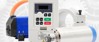
- Selecting the type of cooling
- Selecting speed and power
- How to make your own spindle from a picture
- Service
Have you been involved in metalworking for a long time or are you just starting to study the theory? We will help you understand the basic skills. In the article we will talk about the machine spindle: what it is, show a photo of the tool holder and talk about how to work with it.
Feed mechanism
The feed mechanism tells the caliper the required direction of movement.
The direction is set with a bit. The bit itself is located in the headstock housing. It is controlled via external handles. In addition to the direction, you can also change the amplitude of movement of the caliper using interchangeable gears of different numbers of teeth or a feed box. In the scheme of machines with automatic feed, there is a lead screw and a roller. When carrying out high-precision work, a lead screw is used. In other cases, a roller is used, which allows you to keep the screw in ideal condition longer for performing complex elements.
Operating principle
Metalworking machines 1A616 operate according to the following principle:
- Before processing, the part is fixed in the equipment chuck or between centers.
- The cutters are mounted in their holder on the support. No more than four cutting elements can be installed at the same time.
- To carry out the manipulation of drilling or cutting internal threads, a suitable tool is fixed in the tailstock quill.
- The main processing of the workpiece is carried out through a combination of translational-rotational movement of the cutter and rotation of the part. This design allows the processing of cylindrical, conical and shaped parts, including screw and end parts.
On the 1A616 metal lathe, the transmission of torque to the spindle and the workpiece is carried out using a belt pulley, which is placed between the supports. If necessary, the V-belt can be replaced without removing the spindle. The design of this equipment provides for the principle of separate transmission to the caliper. It can be moved using a lead screw or a roller. A DC starter is used in the motor winding, providing effective braking of the drive.
Installation procedure
Before installing it, you should carefully check the condition of the surfaces of the spindle and chuck. Surfaces should not have nicks, scratches, burrs or contaminated areas.
Identified defects are eliminated point by point with a file or scraper. You should check the runout of the end and cone of the spindle landing base, which should not exceed three microns.
Place a metal rod or pipe with a diameter of about 20 mm into it. clasp it with your fists. With a partner, grasp the rod on both sides, or using lifting mechanisms, through the mounting loop, move the cartridge onto the mounting stand fixed to the machine support.
Install the guide in the tailstock. The chuck should be shifted by rolling towards the spindle axis.
Using a longitudinal feed, move it to the spindle flange so that the chuck studs do not reach the mounting holes of about 10 mm. The machine should be set to neutral speed to allow the spindle to rotate freely.
Move the tailstock with the quill completely retracted forward towards the chuck so that the guide extends over the entire width of the cam prisms and fix the tailstock.
Clamp the jaws of the chuck to transfer the weight to the guide. Align the key on the spindle flange with the mounting hole. Set the rotary washer to the position of the open holes. Using the quill, push the cartridge forward until it stops.
After making sure that all the stud nuts are out of the back of the spindle flange, turn the rotary washer to the locked position. Tighten the top nut with enough force to transfer the weight of the chuck onto the spindle. Open the cams and move the tailstock back. Compress the nuts according to the rule crosswise, evenly distributing the force between the studs.
After installation is completed, the chuck should be checked for axial and axial runout. If the standards are exceeded, it should be removed and all mating parts of this assembly should be carefully inspected.
Video: installation of a lightweight cartridge on a threaded fastener.
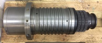
Lathe spindle 16K20. Lathe spindle repair
The spindle is one of the critical parts of the machine, the accuracy and rigidity of which determines the quality of the operations performed on the machine. Deviations from the shape and dimensions of the spindle surfaces are allowed within a very narrow range, therefore increased requirements are placed on the repair of spindles. The specifics of repairing the ends of spindles that have a conical hole and thread, a landing journal or a cone for mounting technological equipment have been determined. If during repairs the dimensions of the surfaces of the spindle end are changed, then the technological equipment supplied with the machine will need to be changed or altered. Therefore, during repairs, they strive to restore it to its original dimensions, especially for the surfaces of the spindle ends.
The choice of method for restoring the main surfaces of the spindle is made depending on the amount of wear.
When the spindle surfaces are worn down to 0.05 mm per side, preliminary grinding is first performed to restore the geometric shape of the surfaces and chrome plating, after which they are finally ground, removing a layer up to 0.03 mm per side.
The surfaces of the spindles, which have wear of more than 0.05 mm per side, are subjected to metal build-up using one of the known methods, and then to mechanical processing.
During restoration, the conical hole at the end of the spindle is usually ground, then the end of the spindle is trimmed to a conical gauge. The end of the spindle flange is also trimmed after restoration by grinding the conical journal at the end of the spindle.
During repairs, the threads of spindles are usually cut to a full profile, and non-standard nuts for them are made anew.
When restoring spindles, it is necessary to choose repair methods that, in parallel with restoring the original dimensions, would ensure an increase in the wear resistance of the surfaces.
A repair drawing of a lathe spindle is shown in Fig. 27. In table. 14 shows the technological route for repairing the spindle.
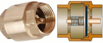
Through hole in spindle
The bore diameter is another important parameter of the spindle. When processing a bar, it limits the maximum diameter of the workpiece that can be processed in this spindle.
If the diameter of the rod is smaller than the diameter of the spindle bore, it is necessary to use special adapter bushings or pipes.
Adapter bushings compensate for the gap between the rod and the spindle hole so that when rotating the rod does not damage the inner surface of the spindle hole. Adapter bushings are made both from welded steel pipes and from polymeric materials such as caprolon or fluoroplastic. Polymer tubes also dampen a significant portion of the vibrations that occur when the rod rotates.
Sometimes during processing it is necessary to place part of the workpiece in the spindle, which can also lead to difficulties if the through hole is smaller than the diameter of the workpiece.
By the way, there is a separate type of spindles for pipe processing. Such spindles are distinguished by a large through hole and the presence of an additional chuck on the other side.
Specifications
The parameters given in the technical data sheet help determine whether this is the device you need for work. We invite you to consider the information provided.
Main settings
- Type - screw-cutting, universal.
- Series - 1A616.
- Accuracy - N (normal).
- The height of the centers is 165 mm.
- The distance between centers is 710 mm.
Spindle
Shaft for securing the workpiece in the chuck:
- Speed limits (forward and reverse rotations) 9–1800 rpm (if necessary, can be ordered with speeds from 11 to 2240 rpm).
- Hole diameter 35 mm.
- Internal Morse taper N5.
- The spindle is braked and the handles are locked.
Caliper and feed
Caliper (support) - a movable element, a unit for securing cutting tools or workpieces:
- Tool holder - 4 cutters.
- Cutter holder (largest dimensions 20x25).
- From the supporting surface to the center line 25 mm.
- From the center axis to the edge of the tool holder 170 mm.
- One front caliper with one cutting head.
- Longitudinal max 670 mm (same values by hand, by roller and by screw).
- Transverse max 195 mm (by hand and with a screw, with a roller this is not possible).
For one dial division:
- Longitudinal 1 mm.
- Transverse 0.05 mm.
For 1 revolution of the dial:
- Longitudinal 110 mm.
- Transverse 5 mm.
Feeds - movement of a cutting element or workpiece in one revolution or working stroke:
In the machines of this series, the limits of longitudinal and transverse feed are set in the range of 0.065 - 0.91 mm/spindle revolution.
Cutting slide
One of the caliper elements. A holder for cutters is attached to it. It can be moved manually along the rotating part of the caliper.
- Maximum rotation angle 90°.
- Scale division, price 1°.
- Maximum movement 120 mm.
- One dial division, price 0.05 mm.
- One revolution of the dial provokes a movement of 3 mm.
Tailstock and frontstock
Tailstock is a unit that helps in supporting the part being manufactured. You can also attach a tool for external processing of the product in it. Under difficult working conditions, it is possible to secure the structure using a tightening bolt and nut.
- Internal Morse cone 4.
- The quill moves a maximum of 120 mm.
- One division of the quill movement scale = 1 mm.
- Lateral displacement 10 mm (forward and backward).
The headstock is a mechanism that moves, receiving impulse from the gearbox through belts and a relieved take-up pulley. Thanks to him it is possible:
- increase eightfold the transmission of motion between the feed and the spindle when cutting threads;
- cut right and left hand threads.
Electrical equipment
The machine operates with a main motion electric motor:
- Power 4 kW.
- 1450 rpm at 50 Hz.
- Power 0.125 kW.
- RPM 2800 at a frequency of 50 Hz.
The ends of the spindles are flanged for a rotary washer GOST 12593
GOST 12593-93 (DIN 55027, ISO 702-3-75). (Instead of GOST 2570-58). Metal-cutting machines. The ends of the spindles are flanged for a rotary washer and flanges for clamping devices.
This standard applies to flanged spindle ends with a short taper of 1:4 (7°7′30″) and a rotary washer for lathes and to flanged clamping devices mounted on spindle ends. GOST 12593-93 is the complete authentic text of ISO 702-3-75 “Machines. Spindle ends and faceplates. Dimensions for interchangeability. Part III. Bayonet type."
The flanged ends of type B spindles have through mounting holes around the circumference of the flange and a bayonet rotary washer , which are used to fasten the cartridge without screwing the fastening nuts, which allows you to quickly fasten and remove the cartridges. For the ends of spindles of this type (B), type 3 quick-change chucks must be used according to GOST 2675-80 Type 3 .
Fastening the chuck to the flange end of the spindle under the rotary washer
An example of the use of flanged spindle ends for a rotary washer
Versions of flanged ends of spindles for rotary washer
Dimensions of flanged ends of spindles for rotary washer
Lathe chuck according to GOST 2675-80 Type 3 for installation with a rotary washer
Flanges for quick-change chucks (type B) with a 1:4 cone fit (7°7′30″) for a rotary washer are made in eight conventional sizes (3, 4, 5, 6, 8, 11, 15, 20) with a nominal outer diameter 102, 112, 135, 170, 220, 290, 400, 540 mm.
Flanged ends of spindles with a rotating washer can be manufactured in three designs:
- Conventional spindle end size 3 and 4;
- The nominal size of the spindle end is 5, 6, 8;
- The nominal size of the spindle end is 11, 15, 20.
The figure shows the installation of a quick-change lathe chuck 2 on a flanged spindle using a bayonet rotary washer 1. Studs 5, which have a cylindrical thickening with a key flat in the middle part, are screwed into the end of the chuck and, when installed, are passed through the hole in the flange and rotary washer 1. After this the washer is turned clockwise and the chuck is clamped onto the spindle cone with nuts 6.
The rotary washer itself is attached to the spindle flange using bushing 3 and screw 4 (option 1) or only screw 7 (option 2), while it remains movable and can rotate on the spindle within the elongated mounting hole.
Mounting on a flanged spindle with a rotating washer takes little time, however, the flange connection ensures high centering accuracy (no backlash) and complete reliability at high spindle speeds.
Machine gearbox design
The gearbox in this lathe model includes:
- 3 cylinders located one behind the other with 3 bearings;
- 3 single gears that form two active gears.
These units provide rotation of the axis, through the shaft, gear-type working transmissions. If it is necessary to set an increased speed of the axle, it is connected directly to the shaft using a claw coupling.
Regulation requires sequential manual actions:
- Determining the cutter holder into the desired position;
- Adjusting the position of the tailstock of the unit;
- Caliper control (main module).
Tailstock
The support unit designed to support the workpiece in alignment with the spindle head is called the tailstock. The tailstock includes a quill - a movable device that is moved along the axis of the workpiece using a screw driven by the feed flywheel.
The numbers indicate:
- Feed handwheel.
- Body fixing eccentric lever.
- Quill lock.
- Tailstock housing.
- Pinol.
- Center.
- Technological holes.
- Body base.
- Body transverse movement bolt.
Before starting work, it is recommended to move the tailstock towards the spindle and check their alignment visually. In case of doubt, one end of the test rod (workpiece) is clamped in the spindle head, and the second end is supported with the center of the tailstock moved into place. Then a rigidly fixed micrometer is moved along the frame guides along the entire length of the rod. The probe of the device must touch the rod - this is how the axial runout of the workpiece is checked. If runout exists, then thin adjustment plates are placed under the base of the tailstock, trying to reduce the axial runout to minimum values or to zero.
The tailstock can serve not only as a supporting element, but also as a holder for some types of tools. Drill, tap, internal cutter - many of these items can be mounted in a quill.
The inside of the quill is machined to a Morse taper, so the tool shanks must also have this taper. The design of the tailstock is made in such a way that when rotated back, the quill is retracted into the body to a certain depth. At this time, the end of the screw moving it rests against the end of the tool inserted into the quill. In this way the tool is pushed out of the quill.
The simplicity of the tailstock design does not eliminate the need for its adjustment, tuning or repair.
After long-term operation or as necessary, the tailstock is inspected. In the case of repairs, after completing all the necessary work or replacing parts, the tailstock is adjusted, which is called adjustment.
When performing any work on adjusting and tuning metal-cutting machines, adjustment plates made of wood are not used because of their softness.
Main parameters of VMS
The main parameters: engine power and torque, rotation speeds, permissible cutting forces, were assigned based on an analysis of the processing modes of steel and aluminum workpieces with face, long-edge, end, disk cutters, as well as boring, drilling and thread-processing tools (drills, reamers, cutters and etc.). Hard alloy and ceramics were used as tool materials. When choosing processing modes, we took into account the fact that when accelerating the above-determined rotation speeds, a gap may arise in the conical connection of the mandrel and spindle, which must be eliminated. The main parameters of the VMS developed within the framework of the state contract are presented in the table.
Fig.5. VMS HSK 100 (longitudinal section)
In Fig. Figure 5 shows the design of a VMS with a HSK-A100 cone. The rotor 1 of the electric motor is installed with interference to transmit torque to the spindle 2. The influence of the electromagnetic fields of the motor is reduced by rings 3 made of non-magnetic material, which can also be used for balancing. Spindle 2, together with the electric motor rotor and other rotating parts, is balanced until a residual imbalance is achieved, at which the center of gravity of the spindle shifts by no more than 1...2 µm. The stator 4 with a cooling jacket 7 is installed in the VMS housing 5 and is cooled when liquid is supplied to the cavity 6 of this jacket. The same system is used to cool the bearings. The front support of the spindle is double angular contact ball bearings 8 and 9, the tension in which is provided by springs 10 (at high rotation speeds) and pneumatic cylinder 11 (at lower frequencies and higher loads). The tool is installed in a mandrel 12, which is secured using a clamping mechanism 13 on the spindle, based in a connection 14 of the HSK-A type. The release of the mandrel 12 is carried out by supplying oil under pressure into the right cavity 15 of the hydraulic cylinder 16, the movable body of which is connected to the spindle 2 through the clamp 17. Thus, when the mandrel 12 is released, the axial force of the spring release is perceived only partially by the spindle supports. The angular position of the spindle is monitored by a sensor, which consists of a magnetized disk 18 mounted on the spindle and a reading head 19 mounted on the housing flange. The vibration sensors 20 and the movement of the front end 22 are located in the VMS housing. Temperature sensors are located in close proximity to the outer rings of the supports and in Fig. 5 are not shown. The coolant supply is carried out through the nozzles 23 or through the hole in the rod 24 of the clamping mechanism 13.
Engine power
The spindle motor power, as well as the maximum rotation speed, should be selected based on the tasks.
Heavy machining is associated with heavy loads on the spindle motor, which can cause it to overheat and prematurely fail. As with maximum speed, it is important to consider the material that the machine will be cutting. Non-ferrous metals, for example, do not require much power from the spindle, while viscous and hard materials such as titanium, stainless steel or heat-resistant steel, on the contrary, are very demanding on power.
An operation that consumes a lot of power in the manufacture of parts is drilling, in which the contact area of the material with the tool is maximum.
When choosing a power characteristic, you should take into account the need to work with large diameter drills. For example, when drilling heat-resistant steel with a drill with a diameter of 50 mm and a rotation speed of 637 rpm, a power of at least 13.3 kW is required from the engine.
The formula by which you can calculate the required power:
Where
Pmot – power consumption
Q – specific material removal
kc – specific cutting force
η – machine efficiency (0.7-0.95)
Specifications often specify two spindle power ratings: continuous/continuous duty (eg ED 100%) and intermittent duty (eg ED 40%).
Continuous mode is designated S1 (according to the IEC34 standard).
S1 - continuous mode (constant load sufficient to establish thermal equilibrium in the engine)
The intermittent operating mode is designated S6, provided for by the same IEC34 standard.
S6 is a sequence of identical cycles, each of which includes operating time at constant load and idle operating time.
Each engine is marked with a mode that corresponds to the declared characteristics.
Below is a power graph using the example of a CTX510ecoline machine spindle. The graph shows two curves: the upper (dashed) line is S6, the lower (solid) line is S1. The graph shows that after reaching 500 rpm, power no longer increases with increasing speed. This is due to the fact that the engine speed is controlled until the nominal spindle speed of 500 rpm is achieved by adjusting the voltage on the motor stator, while the sliding of the electromagnetic field in the stator is maintained. After reaching the nominal speed, adjustment is carried out by changing the slip of the magnetic field. This leads to a decrease in engine torque, but maintains its power as the speed increases.
Thus, when choosing spindle power, it must be remembered that different operating modes achieve different power characteristics. In this case, the peak power value can be obtained only when the rated engine speed is reached. The graph clearly shows that the nominal speed of this engine is 500 rpm. The power for intermittent load is 33 kW, and for constant continuous load it is 22 kW.
It follows from the graph that this spindle will provide us with the necessary power when drilling a hole with a diameter of 50 mm at a rotation speed of 637 rpm under any operating conditions.
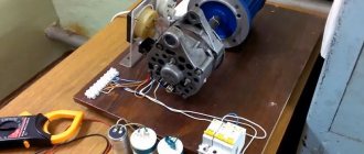
Making the front (back) headstock
For a homemade machine, you can make a headstock with your own hands. Suitable:
- wooden board;
- thick plywood (10 mm);
- a metal sheet of small thickness that can be cut with metal scissors.
It is easier to make a headstock if a drill is chosen as the basis for the lathe. You need to make a stand with your own hands, where the drill will be fixed rigidly and its axis will be strictly horizontal.
Both centers of the headstocks must be firmly attached; this is an important condition. The tailstock should be able to move along the axis of rotation and be firmly fixed in the right place
Read also: Do-it-yourself workbench for a miter saw
The type of electric drive and its power are selected with your own hands, depending on the future purpose of the lathe. But the engine power should not be less than 250 W, otherwise nothing sensible can be turned on the machine.
Detailed video about the design of the headstock:
Mini machine for small jobs
Often there is a need to turn several small wooden parts, in this case it is not at all necessary to make a full-fledged machine; you can get by with a mini-wood lathe. Its production does not require much labor and will not take much time.
The design of such a machine is extremely simple. A motor from an old tape recorder, powered from an external power supply, is ideal as an electrical component. The bed of the mini-machine will be a piece of board of the required length.
The engine must be secured. Of course, a belt drive is not suitable for a small machine; the workpiece will have to be mounted on the motor shaft. The best device for this is a faceplate. The drive housing is a U-shaped plate, in the center of which a hole is drilled for the shaft. The engine in the housing is mounted on the frame using self-tapping screws.
The main part of the machine is ready, all that remains is to make the tailstock. Its body is made of a block of suitable size. A hole for the shaft is drilled in it exactly at the height of the engine; a dowel-nail of suitable length is used as it. The headstock is attached with glue and several screws.
Using a power source with the ability to adjust the output voltage, you can create a machine with variable rotation speed. It is convenient to regulate the speed using the foot control pedal. The design of this device can be very diverse, it all depends on the available parts.
Classification of spindles by type, size and diameter
There are various bases for classification. The first, and perhaps the main one, is what equipment the unit is intended for. Of course, different machines and electrical equipment require different instruments.
The second principle of differentiation is size. The devices come in different sizes, designed for industrial use and private use. In this regard, a variety of consumable parts are needed - larger and smaller. If you want to replace the spindle on your own machine, then when purchasing you must indicate the number of your equipment, name and year of manufacture (there may be different modifications).
Well, the last, but not intended, classification is by type. Shafts can be:
- Collector. This is a device that includes a high-speed collet roller. The main areas of use are milling machines, as well as engraving operations.
- Specialized for high speeds. They allow you to achieve significant metal processing speeds, therefore increasing productivity. But since good quality can only be achieved with great precision, high-speed models are used mainly only on CNC equipment. You can buy such machines on the website.
- Design with built-in cooling. The cooling system can be supplied through a part or liquid, or cold air. This increases the cutting speed and the degree of surface roughness, and friction becomes less, so wear also comes later.
There is another classification - by manufacturer. Of course, European production is more preferable than Chinese. In Europe, porcelain bearings are often used, which provide very positive performance.
The principle of operation of the spindle and what it consists of
Almost all equipment with this element involves using a cutting edge on the prepared material. The design feature of the shaft is that it is possible to securely fix the tool in one of the machine operating modes - power or high-speed. In the second case, the main task of the device is to cut off the top layer from the surface of the workpiece as quickly as possible. The high-speed operating principle has its own special features:
- Productivity increases. Before simply choosing a high rotation speed, it is necessary to take measurements and enter all the parameters into the technological map.
- This option is most widespread in the case of finishing turning or fine milling, since only an extremely thin layer needs to be removed at high speed.
- The most common type of design is an asynchronous motor with a belt or gear drive.
- But sometimes there is simply no intermediary element. But because of this, you should not put too much force on the device, as this threatens to overload the motor. But this also significantly reduces the minimum dimensions of the entire installation, which is why direct connection technology is used in various hand-held power tools.
The second category - power devices - have the following characteristic features of manufacture and operation:
- Between the cutter (drill) and the fastening device of the electric spindle itself, it is necessary to insert bushings - these are conical spacers, which significantly increase the positive qualities of the product and reduce vibrations, and have a good effect on strength. They must be selected depending on the shank - diameter and type.
- It is not recommended to connect directly to the motor, as variable load will damage it. The main transmission method is V-belt or using gears.
DIY lathe headstock
The headstock for a lathe can be made independently without any problems.
For this purpose you will need:
- Wooden plank.
- Plywood, ten millimeters thick.
- A thin sheet of metal that is cut with special scissors.
It is much easier to make a headstock with your own hands if the basis of this device is an ordinary unnecessary drill. After this, it will only be necessary to make a stand, which will subsequently be the mounting platform for the drill, which has a strict horizontal axis.
The middle of the front and middle of the tailstock must be securely fastened, this is extremely necessary. For the tailstock, it is necessary to establish in advance the limits of the possibilities of wrapping along the axis and rigidly securing it in place.
The power of the electric motor should be selected independently, based on the purpose of the turning device. Although the engine power does not need to be less than 250 W. Otherwise, it will not be possible to turn out any necessary parts.
What parts can it process?
Lathes can process parts that have the form of a rotating body. These include:
- shafts;
- axles;
- disks;
- trunnions;
- flanges;
- couplings;
- rings;
- bushings;
- nuts, etc.
In addition, you can cut internal and external threads, turn and boring various surfaces, trimming ends, turning internal and external grooves, drilling, reaming holes, etc.
As you can see, a lathe is used for many operations and is necessary in any production. When considering different types of equipment, you need to keep in mind that the possibility of installing additional equipment can significantly expand the operations performed.
Application of CNC
Modern lathes, especially foreign ones, are numerically controlled. This allows for high processing accuracy.
The features of such machines are the following nuances:
- All moving parts of the machine are controlled by a mini control unit. The machine has a complex electrical circuit.
- All parameters of the CNC machine exactly comply with GOST and are also described in the equipment passport. Accuracy indicators, dimensions, and speed are indicated here.
- Machines of this kind can be used at home because they are small in size, but can withstand surprisingly high loads for their size.
- The equipment has an indication, as well as a display for entering information.
- Benchtop CNC machines are used for high-precision machining of small parts. At the same time, home production has a high profitability rate.
Important! Most of these machines are produced abroad, and therefore they do not comply with Russian GOST.
Selecting the type of cooling
Cooling of the rotation zone is required to increase service life. There are two types.
Water (liquid)
Differences:
- They are very quiet - the liquid flows almost silently. But at the same time there is another loud sound from the movement of the impeller.
- The presence of a circuit that includes a system of tubes, a container, and a pump. It is necessary to constantly monitor the moisture supply and its temperature.
- Can operate at low speeds.
Air
Distinctive features:
- Strong and not the most pleasant sound.
- Chips may fly away under the influence of a jet of air.
- It is necessary to clean the shirt where metal particles become clogged at regular intervals.
- It is required to monitor the temperature very carefully; ideally, install a sensor with a signal, because the entire device is very sensitive to overheating.
As a result, we recommend using the air option when working with soft materials, but when the workpiece is made of durable metal, it is better to use liquid cooling.
Headstock device
The main component of the front tank is the spindle. The spindle head is fixed to the left edge of the bed. This is the most important detail of the entire structure.
Various necessary fixtures, tools, and mandrels are fixed in the inner conical hole of the spindle.
How does it work
The movement of the spindle is transmitted from the V-belt pulley. All shafts and the spindle itself are mounted on rolling bearings.
When the machine rotates in a forward direction, large torques are required. This occurs due to the large number of discs that are located on the left side of the friction clutch.
If the gearbox is fixed in the bed frame, then it is connected to the spindle by a belt drive. Such equipment models are called split-drive machines.
Torque
Torque is another power characteristic of the spindle, directly dependent on power:
Where
τ – torque
P – power
ω – angular velocity
The amount of spindle torque is influenced by its design. There are several types of spindle drive: as a rule, the greatest torque is developed by a spindle with a gear drive. High torque is needed for processing tough materials such as titanium, stainless steel or heat-resistant steel.
Returning to the drilling example, you can see that to drill a hole with a diameter of 50 mm with a spindle speed of 637 rpm, a torque of 190.15 N/m is required. This is quite a large value.
Formula for calculating torque when drilling:
Where
Mc - consumed torque
Dc - drill diameter
kc - specific cutting force
f - feed per revolution
By analogy with power, torque is often specified for continuous duty (S1/ED100%) and intermittent duty (S6/ED40%).
Below is a graph of the spindle torque of the CTX510ecoline machine:
By analogy with the power graph, the torque graph shows two curves: the upper (dashed) line is S6, the lower (solid) line is S1. The graph shows that up to 500 rpm the torque is maximum, and with a further increase in the speed it decreases. Torque in the engine is created due to the sliding of the magnetic field in the stator: when the rated speed is reached, the sliding begins to change, which causes a decrease in torque.
Thus, it should be taken into account that torque, as well as power, depends on the operating mode of the engine: with intermittent load and up to rated speed, a maximum torque value of 630.6 N/m is achieved, and at maximum speed in the same mode, torque will be approximately 100 N/m.
The graph shows that a spindle with such characteristics provides the necessary torque when working with a drill with a diameter of 50 mm with a spindle speed of 637 rpm in any operating mode.